
The Programmable Interrupt controller is commonly known as PIC microcontroller. This 8259 has various operating modes which are explained below. The various modes of operation of PIC microcontroller are explained in detail.
Block Diagram of PIC microcontroller
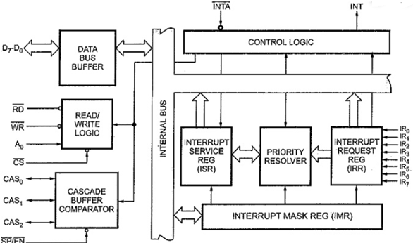
Data Bus Buffer:
It is 8 bit data but. This data bus sends control words to 8259A. This data bus allows 8259A for sending interrupt opcodes and also the interrupt service subroutine.
Read/Write Logic:
When chip select input is low the read and write controls the data flow on the data bus.
Control Logic:
If 8259 is enabled, then interrupt sets the INT output pin high. The control logic also has input and output lines.
Interrupt Request Register (IRR):
There are 8 interrupt inputs. These interrupts set corresponding interrupt bits of IRR when there is a request from other devices.
Interrupt Service Register (ISR):
It stores all the levels that are currently being serviced.
Interrupt Mask Register (IMR):
It can be programmed by OCW and is used to store the masking bits of interrupt lines which are to be masked.
Priority Resolver:
The priorities of the bits set by interrupt request register are maintained here.
Cascade Buffer Comparator:
Cascading operation signals are controlled here. The signal to enable buffers is also generated here. Hence, the first is master and second is called slave. The SE/EN pin decides whether it operates as master or as slave.
CAS0-CAS2 pins are output for master and input for slave.
SP / EN (Slave Program /Enable Buffer):
When we need to operate it as a master this pin is set high. For operation as a slave it is set low.
Priority Modes and Other Features
The various modes of operation of the Block Diagram of 8259 Programmable Interrupt Controller are :
- Fully Nested Mode
- Special Fully Nested Mode (SFNM)
- Rotating Priority Mode
- Special Masked Mode
- Polled Mode
Fully Nested Mode (FNM) :
It is the default mode with IR0 having highest priority and IR7 with lowest priority. The bit in ISR is set when the interrupt is acknowledged. It also accepts highest priority interrupts and sends the vector address of this interrupt.
End of Interrupt (EOI):
Before exiting from interrupt the CPU sends EOI command and the ISR bit is reset. The highest level in ISR represents the last interrupt. Hence, the CPU sends non specified EOI.
Special Fully Nested Mode (SFNM):
To overcome the above mentioned problem this is used. It is set by ICW4
Rotating Priority Mode:
The Rotating Priority mode can be set in Automatic Rotation, and Specific Rotation.
Special Mask Mode:
The lowest priority interrupts are present in case any interrupt is in service. Then the corresponding bit is set high in ISR.
Poll Mode:
The status of interrupt requests is monitored by poll command. The INT output is not used in this mode.During this read operation the 8259A provides polled word and sets ISR bit of highest priority active interrupt request FORMAT.
I = 1 means that more than one interrupt request is active.
I = 0 means that no interrupt request is active.
W2 W1 W0 —>This is a Binary code of highest priority active interrupt request.
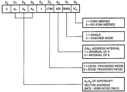
Firstly we see Control word (ICW1) is below:
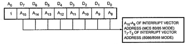
Now another Control word (ICW2) is below:
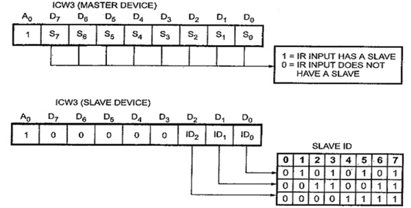
Also the Control word (ICW3) is below
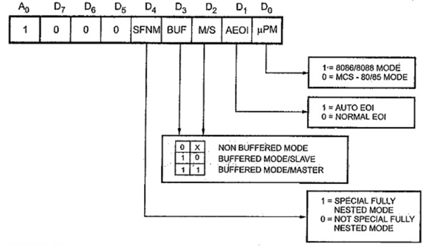
Lastly Control word (ICW4) all 8 bits is below
Interested in learning about similar topics? Here are a few hand-picked blogs for you!
- Fourier Transform and its properties
- What are Encoders and Decoders?
- Huffman Coding with example
- What is Z-transform?
- FFT and its properties