
Nyquist Plot gives the frequency response as well as comments on the stability and the relative stability of the system.
Nyquist Stability Criteria:
The Nyquist criteria is a semi graphical method that determines stability of CL system investigating the properties of the frequency domain plot (Polar plot), the Nyquist plot of the OLTF G(S) H(S) is L(S)
L(S) = G(S)H(S)
Specially, the Nyquist plot of L(S) is a plot which we draw by substituting S=jw and varying the value of w as per the polar plot. In polar plot we take one sided frequency response ( 0 – ∞) in Nyquist plot we will vary the frequency in entire range possible from ( -∞ to 0 ) and (0 to ∞ )
Nyquist Criteria also gives :-
(1). In addition to providing the absolute stability like other plots, the Nyquist criteria also gives information on the relative stability of a stable system and the degree of instability of an unstable system.
(2). It also gives indications on how we can improve the system stability.
(3). The Nyquist plot of G(S) H(S) is the polar plot of G(S) H(S) drawn with wider range of frequency ( -∞ to ∞ ) and along the Nyquist path.
(4). The Nyquist plot of G(S) H(S) gives information on frequency domain characteristics such as B.W, gain margin and phase margin.
Construction of Nyquist Plot
Encirclement :
A point or region in a complex function phase i.e. S-plane is said to be encircled by a closed path if it is found inside the path.
Assumption :-

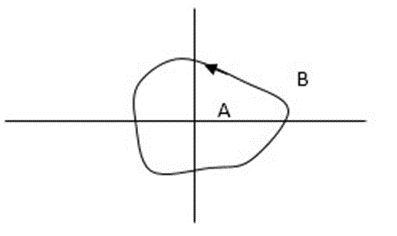
In this example the encirclement of point A is by the closed path Y. Since, A is inside the closed path point B is not encircled by y. it is outside the path. Furthermore when the closed path Y, has a direction assigned to it, encirclement, if made, can be in the clockwise direction or in the anti-clockwise direction.
Point A is encircled by Y in an anticlockwise direction. We can say that the region inside the path is encircled in the prescribed direction and the region outside the path is not encircled.
Enclosure
A point or region is said to be enclosed by a closed path if it is encircled in the counterclockwise direction, or the point or region lies to the left of the path (always), when the path is traveling in the prescribed direction.
The concept of enclosure is particularly useful, if only a portion of a closed path is shown.
In this example the shaded region are
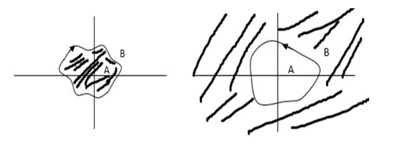
Let path Y enclose the area as we see above. In other words, the enclosure of point A is by Y in fig a. but there is no enclosure by Y in fig b. and for point B it is vice versa.
No of encirclements and enclosures
As it’s overlapping but 2 times in Same direction
When the closed path Y encircles any point, a no. N can is then the number of encirclements. The magnitude of N can be determined by drawing an arrow around the closed path Y.
Taking an arbitrary point S, and then moving around in clockwise direction and anti-clockwise direction respectively. We are getting a direction.
The path followed by S1 gives us the direction and this path which covers the total number of revolutions traveled by this point S1 is N or the net angle is ‘ 2 π N ’.
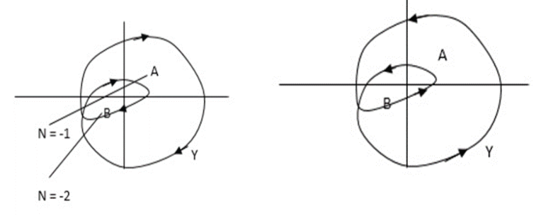
For B = 2 = N for A = 1 = N
In this eg. point A is encircled ones (or 2 π radians) by function Y and also point B is encircled twice (or 4 π radians)all in clockwise direction.
In diagram b again the encirclement of points A and B is in counter clockwise direction thus for this diagram the enclosure of A is one’s and that of B is twice.
By definition M is +ve for anticlockwise(direction) encirclement and –ve for clockwise encirclement.
OLTF as G(S) = (S + Z1)(S + Z2)/(S + P1)(S + P2) H(S) = 1 – – (1)

CLTF = G(S)/1 + G(S)
CE = 1 + G(S)
= 1 + (S + Z1)(S + Z2)/(S + P1)(S + P2)
CE = (S + P1)(S + P2) + (S + Z1)(S + Z2)/ (S + P1)(S + P2) – – (2)
# Zeros of the characteristic equation are poles of CLTF (3 and 4).
For the closed loop system to be stable, zeros of CE(i.e. poles of CLTF) should not be located at the right half of the S-plane.
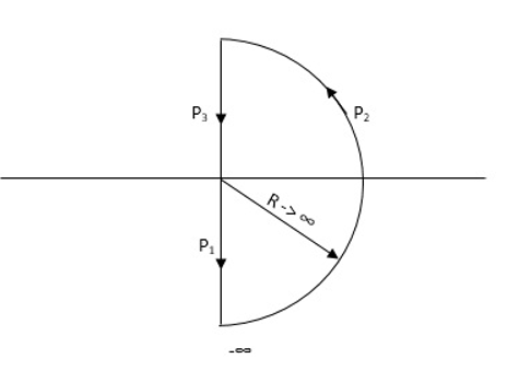
Nyquist Path
Then consider a contour, which covers the entire right half of the S-plane.

If q(s) maps each and every point along the boundary of contour then
q(S) =1+G(S)H(S)
We draw the CE is in S-domain. Now, as the CE : q(s) = 1 + G(S)H(S) contour is into the S-plane.
Hence q(S) contour may encircle the origin. Thus, the number of encirclement of q(S) contour with respect to origin is
N = Z – P
Where : Z1P is zeros and poles of q(S)[CE]
N = Total no of encirclement of origin
· Z1P = Zeros and poles of CE in the right half of S-plane
** for the CL system to be stable Z=0 always.
Important
# Open loop System(stable) :-
When OL system is stable P=0 i.e. no of poles on right half
N = Z – P
If P = 0
N = Z
- Now for CL system to be stable Z = 0
- N = 0
- i.e. q(s) contour should not encircle the origin.
# Open loop system(unstable) :-
Let P = 1 i.e. one OL pole is located in right half of S-plane i.e. OLTF is now unstable.
As N = Z – P
N = Z – 1
For CL system to be stable the only criteria is (Z=0) i.e.
N = -1
Therefore, q(S) contour should encircle the origin one’s in CW direction.
Key takeaway:
(1). When the OL system is unstable then corresponding CL will be stable only when q(S) contour will encircle origin in CW direction.
(2). The no of encirclements should be equal to no of open loop poles located in the right half of S-plane.
** We can calculate the no of encirclements(N) by using G(S) contour (instead of q(S) contour) but the reference is -1+j0 instead of 0+j0 i.e. the no of encirclements should be w.r.t -1+j0 and not with the origin.
Interested in learning about similar topics? Here are a few hand-picked blogs for you!
- What is ZigBee?
- Encoders and Decoders
- Working of UART
- Classification of FFT
- Fourier Transform and its properties