
DC Potentiometer is an instrument which measures voltage. It calculates the potential difference after comparing unknown and known voltage values. The DC potentiometer can also measure current, resistance and calibration of ammeter and voltmeter. The types of DC Potentiometer are also explained in this section.
Crompton Potentiometers
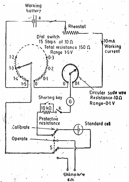
The slide wire type potentiometer is not a practical form of construction. Since the long side wire is not capable of reading the length shown. The long slide wire also cannot read value with accuracy. The size of modern laboratory potentiometers is small as they use small circular wires and calibrated dial resistors. The circuit is shown in the figure.
As shown in figure it has only one dial. This dial has 15 steps and each step has a precision resistor. We can also see a single turn circular slide wire . For the case shown the resistance of slide wire is 10 Ω each. Therefore the total resistance of the dial becomes 150Ω and also additional slide wire resistance is 10Ω. Since the value of working current is 10mA in the potentiometer each step of the dial switch has value 0.1V.
There are 200 scale divisions on the slide area. This is because the value of total resistance of slide wire corresponds to a voltage drop of 0.1V and each division of slide wire now becomes 0.1/200 = 0.0005V. This potentiometer is provided with a double throw switch which allows the connection of either the standard cell or unknown emf to be applied to the working circuit. A key and protective resistance is used in the galvanometer circuit. In order to operate the galvanometer at its maximum sensitivity provision is made to short the protective resistance when near the balance conditions.
Vernier Potentiometers
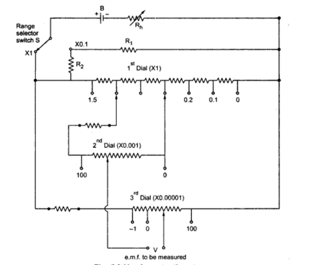
The main difference in the simple and vernier potentiometer is that it uses three measuring dials. The slide wire is not used in this type of potentiometer. The main dial that is the first dial measures up to 15V range in steps of 0.1 volts. The second dial reads upto 0.1V in steps of 0.001 volts on the range. It consists of 102 studs. The third dial again with 102 studs measures from 0.00001 to 0.001 volts in range. This third dial provides true zero and negative settings.
The function of range selector switch S has range resistance R1 and R2. The two coils of the main dial are connected in shunt with the resistance of the second dial. The moving arm of the second dial carries two contacts which are placed two studs away from each other. The value of voltages which the vernier potentiometer reads are 10μV on X1 and 1μV on X0.1 range. To have a voltage reading of 0.1μV one more range X0.01 may be provided.
Sometimes thermal shields are also used to enhance the process of reduction of potentials.
Problem :
During the measurement of low resistance using Potentiometer the following readings were obtained
The Value of Voltage drop of the low resistance =0.4221V
Standard resistance 0.1 Ω voltage drop = 1.0235 V
Find the value of unknown resistance current and also the power lost in it.
Solution:
Resistance of the unknown resistor R = VR/VS = 0.4221/1.0235 x 0.1 = 0.041218Ω.
Current through the resistor = VB/S = 1.0235/0.1 = 10.235 A
Power loss in unknown resistance = I 2 R = (10.235) 2 x 0.041218 = 4.13 W