
There are three operational amplifiers in the circuit of an Instrumentation Amplifier. The input of the differential amplifier is a non- inverting amplifier. For exact measurement of each input data from transduces this circuit provides high input impedance. The basic circuit for instrumentation amplifiers is shown.
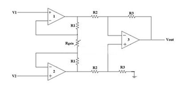
The input stage of the inverting amplifier is formed by connecting two non-inverting amplifiers represented as op-amps 1 and 2 in above figure. The output stage of the instrumentation amplifier is a difference amplifier which is the op-amp 3 in the figure above.
Working of Instrumentation Amplifier
The output voltage Vout of the difference amplifier which is actually the output stage of the instrumentation amplifier. This output voltage Vout is then difference between the input signals applied at the input terminals.
Let us consider Vo1 and Vo2 the output voltages of the two op-amps 1 and 2 respectively. Then the value of voltage Vout of difference amplifier is
The value of voltages Vo1 and Vo2 is in terms of the input voltages and resistances. The input stage of the instrumentation amplifier is also shown below.
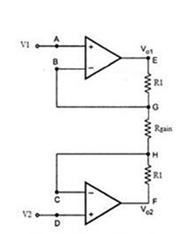
Consider the value of input voltage as V1 at node A. From the virtual ground concept the value of voltage at node B will be V1 . At node G the potential will also be equal to V1 .
Consider the value of input voltage as V2 at node D. From the virtual ground concept the value of voltage at node C will be V2 . At node H the potential will also be equal to V2 .
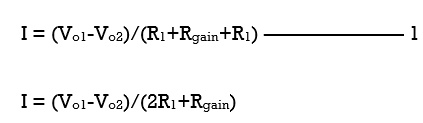
The value of current at input stage is zero because we consider the ideal case. Therefore, the value of current remains same in all the resistors R1, Rgain and R1
At node E and F from Ohm’s Law we can write
As there is no input current at the input stage hence, value of current between node G and H will be
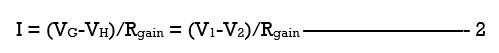
Equating both the equations 1 and 2,
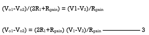
The output of the difference amplifier is
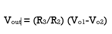
Therefore,
In the equation 3 we substitute (Vo1 – Vo2) value
The output voltage of an instrumentation amplifier is in the above equation. The value of the overall gain of the amplifier is (R3/R2) {(2R1+Rgain)/Rgain}.
Advantages
- Also by varying the value of resistor Rgain the gain of a three op-amp instrumentation amplifier circuit can be easily varied and controlled without changing the circuit structure.
- The value of gain of the amplifier depends upon the external resistor. Then by choosing the resistor value carefully we can easily set the gain.
- As the non-inverting amplifiers form the input stage of the instrumentation amplifier. The value of input impedance of a non-inverting amplifier is very high.
- The value of the output impedance of the difference amplifier is low and this also the output stage of the instrumentation amplifier.
- Since the value of CMRR of the op-amp 3 is very high because of which almost all of the common mode signals will be rejected.
Interested in learning about similar topics? Here are a few hand-picked blogs for you!
- What is ZigBee?
- Encoders and Decoders
- Working of UART
- Classification of FFT https://www.tetezana.org/
- Fourier Transform and its properties