
Multiplexers
- Multiplexer is a special type of combinational circuit.
- It has n-data inputs, one output and m inputs select lines with 2m = n.
- It selects one of the n data inputs and directs it to the output.
- The select lines choose one of the inputs.
- Depending on the code applied at the inputs, one of the n data sources is selected and transmitted to the single output Y.
- The enable input E is responsible for cascading purpose.
- It is an active low terminal hence performs the required operation when it is low.
Multiplexers come in multiple variations
- 2 : 1 multiplexer
- 4 : 1 multiplexer
- 16 : 1 multiplexer
- 32 : 1 multiplexer
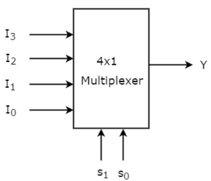
Block Diagram of 4:1 Multiplexer
It has 4 input lines and one output line. There are also two select lines. The four input lines are I0, I1, I2 and I3. Also, S0,S1 have two select lines.
Truth Table of 4:1 MUX
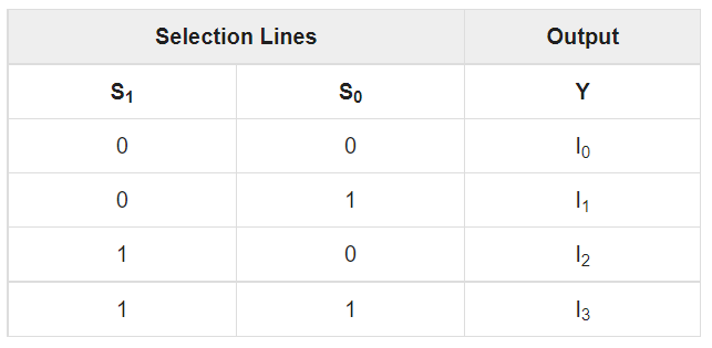
The Boolean expression for output is
By using basic logic gates we can implement the above boolean expression as
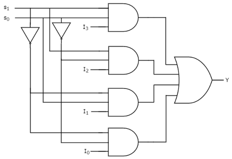
If both the select inputs S0=S1=0 , then the bottom most AND gate is enabled and all other AND gates are disabled. So, the data input I0 is selected and transmitted as output. Hence, we get the output I0.
If both the select inputs S0=S1=1, then the top-most AND gate is enabled and all other AND gates are disabled. So, the data input I3is selected and transmitted as output. Hence, we get output I3.
Demultiplexers
- It has only one input and n number of outputs.
- There are m select inputs.
- It then performs the inverse operation of a multiplexer as it receives one input and distributes it across its outputs.
- As the select line will select only one output line at a time and that input is transmitted through the output line.
- It is equivalent to a single pole multiple way switch .
Various De-multiplexers are used as:
- There is 1 : 2 demultiplexer
- One more type is 1 : 4 demultiplexer
- Also we have 1 : 16 demultiplexer
- Lastly we have 1 : 32 demultiplexer
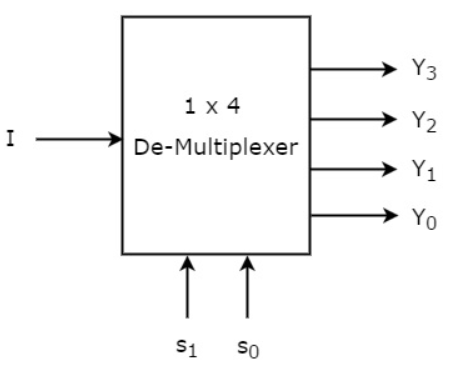
Block diagram
Truth Table
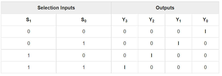
The Boolean expression for each output for above truth table will be
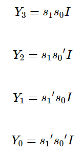
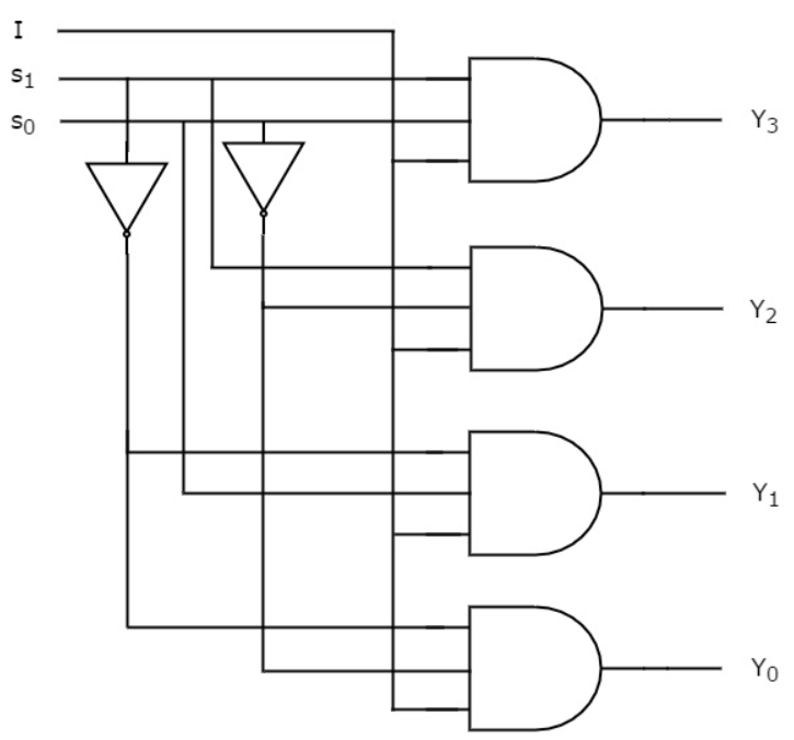
The circuit for above expression using AND, OR gates will be
Interested in learning about similar topics? Here are a few hand-picked blogs for you!
- Fourier Transform and its properties
- What are Encoders and Decoders?
- Huffman Coding with example
- What is Z-transform?
- FFT and its properties