UNIT 3
IIR Filter Design

Solution:
Step 1:

Step 2:
Applying partial fractions on H(s),


Step 3:

Step 4:

2. Find the bilinear transformation which maps points z =2,1,0 onto the points w=1,0,i.
Ans. Let, 
And, 
Since bilinear transformation preserves cross ratios,
Thus we have,


3. Use the bilinear transformation to convert the analog filtrt with system function

 into a digital IIR filter. Select T =0.1
Consider the following system function

Note that the following is the resonant frequency of the analog filter

Consider that the resonant frequency of analog filter must be mapped by selecting the value of parameter
T= 0,1
Use the following mapping for bilinear transformation

Write the system function H(z) of the resultant digital filter

4. Explain frequency wraping in detail.
The bilinear transformation method has the following important features: A stable analog filter gives a stable digital filter. t The maxima and minima of the amplitude response in the analog filter are preserved in the digital filter. As a consequence, – the pass band ripple, and – the minimum stop band attenuation of the analog filter are preserved in the digital filter frame.
• To determine the frequency response of a continuous-time filter, the transfer function Ha(s)Ha(s) is evaluated at s=jω which is on the jω axis. Likewise, to determine the frequency response of a discrete-time filter, the transfer function Hd(z) is evaluated at z=ejωT which is on the unit circle, |z|=1|z|=1 .
• When the actual frequency of ω is input to the discrete-time filter designed by use of the bilinear transform, it is desired to know at what frequency, ωa , for the continuous-time filter that this ω is mapped to.


• This shows that every point on the unit circle in the discrete-time filter z-plane, z= ejωT is mapped to a point on the jω axis on the continuous-time filter s-plane, s=jω. That is, the discrete-time to continuous-time frequency mapping of the bilinear transform is
ωa=(2/T) tan(ωt/2)
and the inverse mapping is
ω=(2/T) arc tan(ωaT/2)
• The discrete-time filter behaves at frequency the same way that the continuous-time filter behaves at frequency (2/T)tan(ωT/2). Specifically, the gain and phase shift that the discrete-time filter has at frequency ω is the same gain and phase shift that the continuous-time filter has at frequency (2/T)tan(ωT/2). This means that every feature, every "bump" that is visible in the frequency response of the continuous-time filter is also visible in the discrete-time filter, but at a different frequency. For low frequencies (that is, when ω≪2/T or ωa≪2/T),ω≈ωa.
One can see that the entire continuous frequency range
−∞<ωa<+∞
is mapped onto the fundamental frequency interval
−πT<ω<+πTω=±π/T.ωa=±∞
One can also see that there is a nonlinear relationship between ωa and ω This effect of the bilinear transform is called frequency warping.

5. Design a discrete time lowpass filter to satisfy the following amplitude specifications: 

Assume 
The pre-warped critical frequency are


Since both the passband and stopband are required to be monotonic, a Butterworth approximation will be used


From the Butterworth design tables we can immediately write

Now find H (z) by first noting that 


Using the pole/ zero mapping formula

We can now write

Find  by setting


Finally after multiplying out the numerator and denominator we obtain

6. Compare Impulse Invariance and Bilinear Transformation
Sr No. | Impulse Invariance | Bilinear Transformation |
1 | In this method IIR filters are designed having a unit sample response h (n) that is sampled version of the impulse response of the analog filter. | This method of IIR filter design is based on the trapezoidal formula for numerical integration. |
2 | The bilinear transformation is a conformal mapping that transforms the j | The bilinear transformation is a conformal mapping tjat transforms the |
3 | For design of LPF, HPF and almost all types of bandpass and band stop filters this method is used. | For designing of LPF, HPF and almost all types of bandpass and band stop filters this method is used. |
4 | Frequency relationship is non –linear. Frequency warping or frequency compression is due to non – linearity. | Frequency relationship is non linear. Frequency warping or frequency compression is due to non – linearity. |
5 | All poles are mapped from s plane to the z plane by the relationship | All poles and zeros are mapped. |


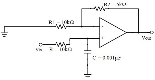
7. Let us consider the Butterworth low pass filter with cut-off frequency 15.9 kHz and with the pass band gain 1.5 and capacitor C = 0.001µF.
fc = 1/2πRC
15.9 * 10³ = 1 / {2πR1 * 0.001 * 10-6}
R = 10kΩ
Amax = 1.5 and assume R1 as 10 kΩ
Amax = 1 + {Rf / R1}
Rf = 5 kΩ
8. A Butterworth Amplitude Response design
Let, 

Solution:
Solving for N gives


Matching at 

The normal  from the table is

Frequency seal  impliea that we let
Finally, the frequency scaled system function is

9. Design from a Rational H (s)
Let, 
Solution:
Inverse Laplace transforming yields

Sampling  seconds and gain scaling we obtain

which implies that

Setting  requires that

10. A partial fraction expansion of


The corresponding parallel form I realization is shown below


