Unit - 3
Sliding and Rolling Contact Bearing
Q1) What is sliding contact bearing?
A1)
All machines are made from a few shifting elements and a few desk bound. There is a relative movement among shifting and desk bound elements. Here, additionally the friction will come into play and must be decreased.
The friction is decreased through offering lubricant among the floor shifting in relative movement. For shah and axle, their ends rotating in enveloping hole cylinder isn't the only approach of assisting.
Instead the shaft cease, called journal, can be supported organization in a hoop on whose periphery are positioned t) absorb rollers that are enveloped through some other hang or race.
The out of doors of the outer race is held ifi a few desk bound a part of gadget. In this state of affairs the balls or rollers mH on outer surf. Of internal ring and internal floor of the outer ring, accordingly ensuing in rollitlg friction that is a great deal much less tan &ding friction.
Q2) What are the objectives of sliding contact bearing?
A2)
Objectives:
- Recognize approximately bearing types,
- Describe styles of friction in sliding bearing,
- Provide an explanation for the styles of lubrication and lubricant properties,
- Apprehend theories of bearing and types,
- Describe energy loss in sliding touch bearings,
- Speak bearing design,
- Recognize bearing materials.
Q3) Write a note on sliding contact bearing.
A3)
The supposed layout constantly envisages that rubbing surfaces are completely separated with the aid of using lubricant layer. This isn't always constantly viable however feeding oil below stress among the touch surfaces might also additionally acquire this. This sort of lubrication termed hydrostatic.
The viscosity of lubricant, its chemical composition, stress, load and velocity of rubbing are some of factors. Complete absence of any lubricant layer among surfaces will carry metals in touch. Dry friction is stated to arise among surfaces.
The friction among surfaces will absolutely rely on coefficient of friction among metals of surfaces. The put on will be excessive and temperature will increase.
Boundary friction takes region among surfaces inclusive of magazine and bearing if a small amount of lubricant exists among bearing surfaces. This state of affairs might not lessen the friction considerably.
A moderate development is mixed film lubrication or semi-fluid lubrication wherein a barely thicker movie exists and which lets in load to be partially carried with the aid of using oil movie.
Part of the burden is carried with the aid of using touch floor roughness peaks (asperities). In boundary lubrication the viscosity of lubrication performs small function and its chemical composition turns into greater important.
In case of magazine bearings this situation isn't always accepted and bearing is appeared to have failed if one of these situation has a tendency to exist. However, in tools enamel touch such situation is not unusual place and might cause scuffing.
Additives of positive sorts that could keep on with floor with thickness same to few modules can keep away from scuffing.
A bearing is a gadget detail which help any other shifting gadget detail (referred to as magazine). It lets in a relative movement among the touch surfaces of the members, whilst wearing the load.
A little attention will display that because of the relative movement among the touch surfaces, a sure quantity of electricity is wasted in overcoming frictional resistance and if the rubbing surfaces are in direct touch, there could be fast put on.
In order to lessen frictional resistance and put on and in a few instances to hold away the warmth generated, a layer of fluid (referred to as lubricant) can be provided. The lubricant used to split the magazine and bearing is often a mineral oil subtle from petroleum, however vegetable oils, silicon oils, greases etc., can be used.
Q4) Classify sliding contact bearing depending upon the direction of load to be supported.
A4)
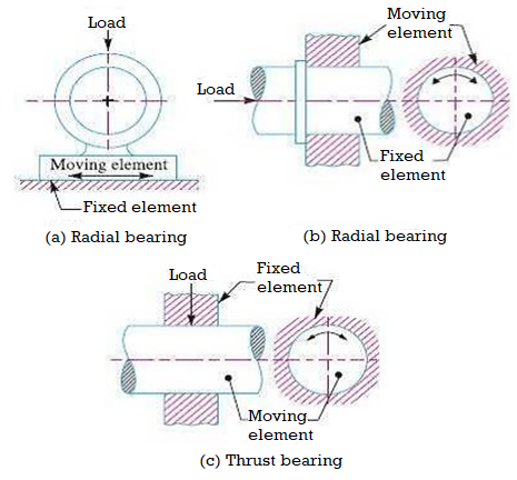
The bearings below this organization are labelled as: Radial bearings, and Thrust bearings. In radial bearings, the weight acts perpendicular to the route of movement of the shifting detail as proven in Fig (a) and (b). In thrust bearings, the weight acts alongside the axis of rotation as proven in Fig (c).
Q5) Classify the sliding contact bearing depending upon the nature of contact.
A5)
The bearings under this group are classified as:
- Sliding contact bearings, and
- Rolling contact bearings.
In sliding touch bearings, as proven in Fig (a), the sliding takes region alongside the surfaces of touch among the transferring detail and the constant detail.
The sliding touch bearings also are called simple bearings. In rolling touch bearings, as proven in Fig (b), the metal balls or rollers, are interposed among the transferring and glued elements. The balls provide rolling friction at factors for every ball or roller.

Q6) Give the types of sliding contact bearing.
A6)
Types of Sliding Contact Bearings
The sliding touch bearings wherein the sliding movement is guided in a instantly line and wearing radial masses, as proven in Fig (a), can be known as slipper or manual bearings. Such form of bearings are commonly observed in cross-head of steam engines.
The sliding touch bearings wherein the sliding movement is alongside the circumference of a circle or an arc of a circle and wearing radial masses are referred to as magazine or sleeve bearings.
When the perspective of touch of the bearing with the magazine is 360° as proven in Fig (a), then the bearing is known as a complete magazine bearing. This form of bearing is generally utilized in business equipment to deal with bearing masses in any radial direction.
When the perspective of touch of the bearing with the magazine is 120°, as proven in Fig (b), then the bearing is stated to be partial magazine bearing.
The maximum not unusual place utility of the partial magazine bearings is observed in rail street vehicle axles. The complete and partial magazine bearings can be known as clearance bearings due to the fact the diameter of the magazine is much less than that of bearing.
When a partial magazine bearing has no clearance i.e. the diameters of the magazine and bearing are equal, then the bearing is known as a geared up bearing, as proven in Fig (c). The sliding touch bearings, in keeping with the thickness of layer of the lubricant among the bearing and the magazine, will also be labelled as follows:
Thick film bearings.
The thick film bearings are those in which the running surfaces are truly separated from each special thru the lubricant. Such shape of bearings are also called as hydrodynamic lubricated bearings.
Thin film bearings.
Such shape of bearings are also called boundary lubricated bearings.
Zero film bearings.
The zero film bearings are those which characteristic without any lubricant present.
Hydrostatic or externally pressurized lubricated bearings.
The hydrostatic bearings are those which could manual steady hundreds without any relative motion a few of the mag and the bearing. This is completed thru forcing externally pressurized lubricant a few of the members.
Q7) Give petroff’s equations
A7)
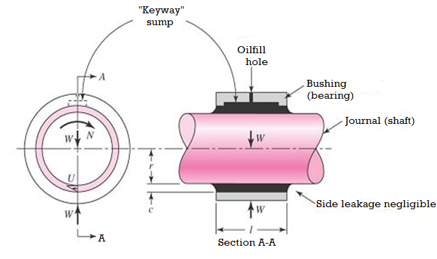
Petroff’s approach of lubrication analysis, which assumes a concentric shaft and bearing, changed into the primary to give an explanation for the phenomenon of bearing friction. This approach, which in the long run produces the equation called Petroff’s Law, is beneficial as it defines agencies of applicable dimensionless parameters, and predicts a reasonably correct coefficient of friction, even if the shaft isn't concentric.
Considering a vertical shaft rotating internal a bearing, it is able to be assumed that the bearing is subjected to a negligible load, the radial clearance area is absolutely packed with lubricant, and that leakage is negligible.
The surface velocity of the shaft is: U = 2*π*r*N where N is the rotational speed of the shaft in rev/s.
• The Petroff equation gives the coefficient of friction in journal bearings.
• It assumes that the shaft (journal) and the bushing are concentric.
• In reality, the shaft is not concentric with the bearing but the coefficient of friction predicted is quite good.
• The shaft is operating at a speed of n
Ԏ = u (U/h) = uπrN/c
T = fWr
Where f is the coefficient of friction
f = 2π2uNr/P c
The non-dimensional quantities (uN/P) & (r/C) are important.
The Sommerfeld number or bearing characteristics number contains many important
S = (r/C)2 uN/P
Therefore,
f (r/C) = 2π2 (uN/P) (r/C)2 = 2π2 S
Q8) Write note on sommerfeld number
A8)
In the design of fluid bearings, the Sommerfeld number (S) is a dimensionless quantity used extensively in hydrodynamic lubrication analysis. The Sommerfeld number is very important in lubrication analysis because it contains all the variables normally specified by the designer.
The Sommerfeld Number is typically defined by the following equation
S = (r/C)2 uN/P
Where:
S is the Sommerfeld Number or bearing characteristic number
r is the shaft radius
c is the radial clearance
µ is the absolute viscosity of the lubricant
N is the speed of the rotating shaft in rev/s
P is the load per unit of projected bearing area
The second part of the equation is seen to be the Hersey number. However, an alternative definition for S is used in some texts based on angular velocity:
S = (r/C)2 uN/P = (r/C)2uwLD/W
Where:
u is angular velocity of the shaft in rad/s.
W is the applied load
L is the bearing length
D is the bearing diameter
It is therefore necessary to check which definition is being used when referring to design data or textbooks, since the value of S will differ by a factor of 2π.
Q9) Explain rolling contact bearing.
A9)
Bearing is a mechanical element that permits relative motion between two parts, such as the shaft and the housing, with minimum friction. The functions of the bearing are as follows:
(i) The bearing ensures free rotation of the shaft or the axle with minimum friction.
(ii) The bearing supports the shaft or the axle and holds it in the correct position.
(iii) The bearing takes up the forces that act on the shaft or the axle and transmits them to the frame or the foundation.
The most important criterion to classify the bearings is the type of friction between the shaft and the bearing surface. Depending upon the type of friction, bearings are classified into two main groups—sliding contact bearings and rolling contact bearings as shown in Fig.
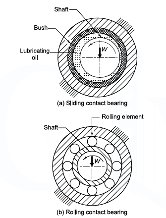
Fig. (a) Sliding Contact Bearing (b) Rolling Contact Bearing
In this chapter we will discuss about rolling contact bearing.
Types of rolling contact Bearings
Depending upon the type of rolling element, the bearings are classified as ball bearing, cylindrical roller bearing, taper roller bearing and needle bearing.
The types of rolling contact bearings, which are frequently used, are shown in Fig. The characteristics of these bearings are as follows:
(i) Deep Groove Ball Bearing: In this type of bearing, the radius of the ball is slightly less than the radii of curvature of the grooves in the races. Kinematically, this gives a point contact between the balls and the races.
(ii) Cylindrical Roller Bearing: A cylindrical roller bearing consists of relatively short rollers that are positioned and guided by the cage. Due to line contact between rollers and races, the radial load carrying capacity of the cylindrical roller bearing is very high.

Fig. Types of Rolling Contact Bearing
(iii) Angular Contact Bearing: In angular contact bearing, the grooves in inner and outer races are so shaped that the line of reaction at the contact between balls and races makes an angle with the axis of the bearing. This reaction has two components- radial and axial. Therefore, angular contact bearing can take radial and thrust loads. Angular contact bearings are often used in pairs, either side by side or at the opposite ends of the shaft, in order to take the thrust load in both directions.
(iv) Self-aligning Bearings: There are two types of self-aligning rolling contact bearings, self-aligning ball bearing and spherical roller bearing.
- The self-aligning ball bearing consists of two rows of balls, which roll on a common spherical surface in the outer race. In this case, the assembly of the shaft, the inner race and the balls with cage can freely roll and adjust itself to the angular misalignment of the shaft.
- There is similar arrangement in the spherical roller bearing, where balls are replaced by two rows of spherical rollers, which run on a common spherical surface in the outer race. Compared with the self-aligning ball bearing, the spherical roller bearing can carry relatively high radial and thrust loads.
(v) Taper Roller Bearing: The taper roller bearing consists of rolling elements in the form of a frustum of cone. They are arranged in such a way that the axes of individual rolling elements intersect in a common apex point on the axis of the bearing. In taper roller bearing, the line of resultant reaction through the rolling elements makes an angle with the axis of the bearing. Therefore, taper roller bearing can carry both radial and axial loads.
(vi) Thrust Ball Bearing: A thrust ball bearing consists of a row of balls running between two rings-the shaft ring and the housing ring. Thrust ball bearing carries thrust load in only one direction and cannot carry any radial load. The use of a large number of balls results in high thrust load carrying capacity in smaller space. This is the major advantage of thrust bearing.
Q10) What is static load carrying capacity?
A10)
The static load carrying capacity of a bearing is defined as the static load which corresponds to a total permanent deformation of balls and races, at the most heavily stressed point of contact, equal to 0.0001 of the ball diameter.
The values of static load carrying capacities are directly given in the manufacturer’s catalogues
Q11) Define dynamic load carrying capacity.
A11)
The life of an individual ball bearing is defined as the number of revolutions (or hours of service at some given constant speed), which the bearing runs before the first evidence of fatigue crack in balls or races.
Bearings are rated on one of the two criteria- the average life of a group of bearings or the life, which 90% of the bearings will reach or exceed.
The second criterion is widely used in bearing industry. The rating life of a group of apparently identical ball bearings is defined as the number of revolutions that 90% of the bearings will complete or exceed before the first evidence of fatigue crack.
The dynamic loadcarrying capacity of a bearing is defined as the radial load in radial bearings (or thrust load in thrust bearings) that can be carried for a minimum life of one million revolutions. The minimum life in this definition is the L10 life, which 90% of the bearings will reach or exceed before fatigue failure. The manufacturer’s catalogues give ready-made values of dynamic load capacities of bearings.
Q12) Explain Stribeck’s Equation
A12)
Stribeck’s equation gives the static load capacity of bearing. It is based on the following assumptions:
(i) The races are rigid and retain their circular shape.
(ii) The balls are equally spaced.
(iii) The balls in the upper half do not support any load.
Figure 3.3 (a) shows the forces acting on the inner race through the rolling elements, which support the static load C0. It is assumed that there is a single row of balls. Considering the equilibrium of forces in the vertical direction,


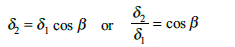
As the races are rigid, only balls are deformed. Suppose d1 is the deformation at the most heavily stressed Ball No.1. Due to this deformation, the inner race is deflected with respect to the outer race through d1. As shown in Fig. 3.3(b), the center of the inner ring moves from O to O’ through the distance ẟ1 without changing its shape. Suppose ẟ1, ẟ2 …… are radial deflections at the respective balls.
Also

According to Hertz’s equation, the relationship between the load and deflection at each ball is given by,
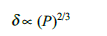
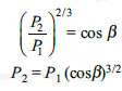
Therefore


From Eq. (b) and (c),
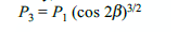
In a similar way,
Substituting these values in Eq. (a),

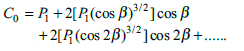
Or C0 = P1M
 where
where
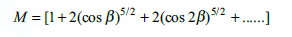
If z is the number of balls,
β = 
The values of M for different values of z are tabulated as follows:
Z | 8 | 10 | 12 | 15 |
M | 1.84 | 2.28 | 2.75 | 3.47 |
z/M | 4.35 | 4.38 | 4.36 | 4.37 |
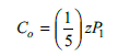
It is seen from the above table that (z/M) is practically constant. Stribeck suggested the value for (z/M) as 5 or M = (1/5)z
Substituting this value in Eq. (d),

 From experimental evidence, it is found that the force P1 required to produce a given permanent deformation of the ball is given by,
P1 = kd2
Where d is the ball diameter and the factor k depends upon the radii of curvature at the point of contact, and on the modulii of elasticity of materials. From Eqs (f) and (g),

The above equation is known as Stribeck’s equation.
Q13) Explain equivalent bearing load
A13)
In actual applications, the force acting on the bearing has two components—radial and thrust. It is therefore necessary to convert the two components acting on the bearing into a single hypothetical load, fulfilling the conditions applied to the dynamic load carrying capacity. Then the hypothetical load can be compared with the dynamic load capacity.
The equivalent dynamic load is defined as the constant radial load in radial bearings (or thrust load in thrust bearings), which if applied to the bearing would give same life as that which the bearing will attain under actual condition of forces.
 The expression for the equivalent dynamic load is given by
P = XVFr + YFa
Where,
P = equivalent dynamic load (N)
Fr = radial load (N)
Fa = axial or thrust load (N)
V = race-rotation factor
X and Y are radial and thrust factors respectively and their values are given in the manufacturer’s catalogues.
The race-rotation factor depends upon whether the inner race is rotating or the outer race. The value of V is 1 when the inner race rotates while the outer race is held stationary in the housing. The value of V is 1.2 when the outer race rotates with respect to the load, while the inner race remains stationary. In most of the applications, the inner race rotates and the outer race is fixed in the housing. Assuming V as unity, the general equation for equivalent dynamic load is given by,
 P = XFr + YFa
In this chapter, we will use the above equation for calculating equivalent dynamic load. The effect of V should be considered in special cases, where the outer race rotates and the inner race is stationary.
Q14) Explain load- life relationship in detail.
A14)
The relationship between the dynamic load carrying capacity, the equivalent dynamic load, and the bearing life is given by,
 L10 =
L10 = 
Where,
P = equivalent dynamic load (N)
L10 = rated bearing life (in million revolutions)
C = dynamic load capacity (N), and
p = 3 (for ball bearings)
p = 10/3 (for roller bearings)
 The relationship between life in million revolutions and life in working hours is given by

Where,
L10h = rated bearing life (hours)
n = speed of rotation (rpm)
Q15) In a particular application, the radial load acting on a ball bearing is 5 kN and the expected life for 90% of the bearings is 8000 h. Calculate the dynamic load carrying capacity of the bearing, when the shaft rotates at 1450 rpm.
A15)
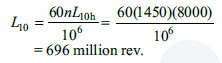
Given Fr = 5 kN, L10h = 8000 h, n = 1450 rpm
Step I Bearing life (L10)
Step II Dynamic load capacity
Since the bearing is subjected to purely radial load,
P = Fr = 5000 N
From Eq. (3.3), (p = 3, for ball bearings)
C = P*(L10)1/3 = (5000)*(696)1/3 = 44 310.48 N
Q16) How bearing life is selected?
A16)
While selecting the proper size of a bearing, it is necessary to specify the expected life of the bearing for the given application. The information regarding the life expectancy is generally vague and values based on past experience are used. For all kinds of vehicles, the speed of rotation is not constant and the desired life is expressed in terms of millions of revolutions. The recommended bearing life for wheel applications is given in Table 1.
Table 1 Bearing life for wheel applications
Wheel application | Life (million rev.) |
Automobile cars | 50 |
Trucks | 100 |
Trolley cars | 500 |
Rail-road cars | 1000 |
In the other applications, the speed of rotation is relatively constant and the desired life is expressed in terms of hours of service. The recommended bearing life for some of the applications is given in Table 2.
Table 2 Bearing life for industrial applications
1 | Machines used intermittently such as lifting tackle, hand tools and household appliances | 4000-8000h |
2 | Machines used for eight hours of service per day, such as electric motors and gear drives | 12000-20000h |
3 | Machines used for continuous operation (24 h per day) such as pumps, compressors and conveyors | 40000-60000h |
Q17) Explain selection of rolling contact bearings from manufacturer’s catalogue
A17)
The basic procedure for the selection of a bearing from the manufacturer’s catalogue consists of the following steps:
(i) Calculate the radial and axial forces acting on the bearing and determine the diameter of the shaft where the bearing is to be fitted.
(ii) Select the type of bearing for the given application.
(iii) Determine the values of X and Y, the radial and thrust factors, from the catalogue (and also in design data handbook). The values depend upon two ratios, (Fa/Fr) and (Fa/C0) where C0 is the static load capacity. The selection of the bearing is, therefore, done by trial and error.
(iv) Calculate the equivalent dynamic load from the equation.
P = XFr + YFa
(v) Make a decision about the expected bearing life and express the life L10 in million revolutions.
(vi) Calculate the dynamic load capacity from the equation
C = P ( L10)1/3
(vii) Check whether the selected bearing of series 60 has the required dynamic capacity. If not, select the bearing of the next series and go back to Step (iii) and continue.
Q18) How cyclic load is design?
A18)
In certain applications, ball bearings are subjected to cyclic loads and speeds. As an example, consider a ball bearing operating under the following conditions:
(i) radial load 2500 N at 700 rpm for 25% of the time,
(ii) radial load 5000 N at 900 rpm for 50% of the time, and
(iii) radial load 1000 N at 750 rpm for the remaining 25% of the time.
Under these circumstances, it is necessary to consider the complete work cycle while finding out the dynamic load capacity of the bearing. The procedure consists of dividing the work cycle into a number of elements, during which the operating conditions of load and speed are constant. Suppose that the work cycle is divided into x elements. Let P1, P2, …….…... Px be the loads and n1, n2,…….. nx be the speeds during these elements. During the first element, the life L1 corresponding to load P1, is given by

Let us assume that the first element consists of N1 revolutions. Therefore, the life consumed by the first element is given by,

Similarly, the life consumed by the second element is given by

Adding these expressions, the life consumed by the complete work cycle is given by

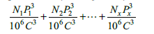
If Pe is the equivalent load for the complete work cycle, the life consumed by the work cycle is given by,


Where, N = N1 + N2 + ……. + Nx
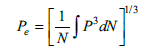
Equating expressions (a) and (b),


The above equation is used for calculating the dynamic load capacity of a bearing.
When the load does not vary in steps of constant magnitude, but varies continuously with time, the above equation is modified and written as
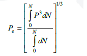

In case of bearings, where there is a combined radial and axial load, it should be first converted into equivalent dynamic load before the above computations are carried out.
Q19) A single-row deep groove ball bearing has a dynamic load capacity of 40500 N and operates on the following work cycle:
(i) radial load of 5000 N at 500 rpm for 25% of the time;
(ii) radial load of 10000 N at 700 rpm for 50% of the time; and
(iii) radial load of 7000 N at 400 rpm for the remaining 25% of the time.
Calculate the expected life of the bearing in hours.
A19)
Given C = 40500 N
Step I Equivalent load for complete work cycle
Consider the work cycle of one minute duration. The values of load P and revolutions N are tabulated as follows:

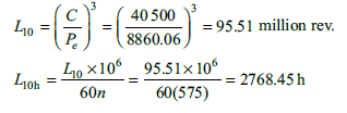
From equation 3.5

Step II Bearing life (L10h)
According to the load life relationship,