Unit - 1
Spur and Helical Gears
Q1) What is gear and give its types.
A1)
Gears are the toothed wheels which transmit the power and motion from on shaft to another by means of successive engagement of teeth.
Selection of Type of gears
During the selection of the type of gear following factors are to be considered
1. General layout of the shaft
2. Speed reduction
3. Power to be transmitted
4. Input speed
5. Cost
Q2) What is the criteria of selection of gear?
A2)
Table 1 General layout of the shaft
Type of Gear | Layout of shafts |
Spur/Helical | Parallel shafts |
Bevel Gears | Perpendicular Shafts |
Worm Gears | Non-intersecting Perpendicular shafts |
Table 2 Speed reduction
Type of gear | Reduction ratio |
Spur/ Helical Gears | 6:1 to 10:1 |
Bevel Gears | 1:1 to 3:1 |
Worm Gears | 60:1 to 100:1 |
- Helical gears are preferred for high speed and power transmission, because in case of spur gears noise is generated due the sudden contact over the entire face width between two meshing teeth whereas in case of helical gears meshing of teeth begin with point contact and it gradually extends along the tooth.
- If cost is taken in consideration, spur gears are cheapest in comparison to all other types of gears due to ease of their manufacturing as well as methods available to manufacture them. Hence, most widely used gears are the spur gears while all other gears are used for specialized operations.
Q3) What are the gear materials?
A3)
Material selection
The desirable properties of gear material are as follows:
- The gear material should have sufficient strength to resist failure due to breakage of the tooth.
- The gear material should have sufficient surface endurance strength to avoid failure due to destructive pitting.
- The material should have low coefficient of friction to avoid failure due to scoring.
Generally gears are made of cast iron, steel, bronze and phenolic resins. Gear material according to load applications are shown in table 1.3.
Table 3 Gear Materials
Gears | Material |
Large size gears | Grey Cast iron |
Medium duty gears | Plain carbon steel |
Heavy duty applications | Alloy steels |
Planetary gear trains | Alloy steel 35NilCr60 |
Worm Gear | Bronze |
Apart from all the above materials non-metals are also used for some kind of gears. In non-metallic gear drives, only the pinion is made of non-metals such as molded nylon, laminated phenolics like Bakelite. The nonmetallic pinions generally run with cast iron gears. Gears made of phenolic resins have low modulus of elasticity and work on marginal lubrication. They can tolerate errors in the tooth profile.
Q4) What are the basic modes of tooth failure?
A4)
Basic modes of tooth failures
There are two basic modes of gear tooth failure—
- Breakage of the tooth due to static and dynamic loads
To avoid this kind of failure gear design parameters such as module, and face width are adjusted in such a way that beam strength of the gear tooth will be more than the sum of static and dynamic load.
2. The surface destruction
The surface destruction or tooth wear is classified according to the basis of their primary causes. The principal types of gear tooth wear are shown in table 4.
Table 4 The Surface Destruction
Wear | Cause | Remedy |
Abrasive Wear | Scratch due to foreign particles in the lubricant, such as dirt, rust, weld spatter or metallic debris. |
|
Corrosive Wear | Caused by extreme pressure additives present in lubricating oils and foreign materials due to external contamination. |
|
Initial Pitting | Caused by the errors in tooth profile, surface irregularities and misalignment. |
|
Destructive Pitting | Occurs when the load on the gear tooth exceeds the surface endurance strength of the material. |
|
Scoring |
|
|
Q5) Write a note on gear lubrication method.
A5)
Gear Lubrication Methods
Proper lubrication of the gear teeth is essential for the satisfactory performance and durability of the gears. Gears are lubricated by grease, straight mineral oils or EP (extreme pressure) lubricants. In gears lubrication can be done in following manners:
- Grease is used as lubricant for the gears of hand-operated mechanisms, where the pitch line velocity is low and the operation is intermittent.
- For medium velocities, the gears are enclosed in a box and dipped in a bath of mineral oil. This is known as splash lubrication.
- In some cases, gears are lubricated by spraying the lubricating oil, in which a jet of oil is directed towards the meshing teeth.
Q6) What is super gear?
A6)
In these types of gears teeth are cut parallel to the axis of shaft shown in figure 1.1 and these gears are used when the axis of connecting shafts are parallel. In case of spur gear involute profile is used for the teeth and these gears imposes only radial loads.
During the engagement of gears smaller gear is termed as pinion while larger gear is termed as gear/wheel.
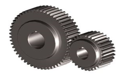
Figure 1 Spur Gears
Number of teeth and face width
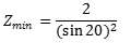
For the design of gears it is very important to calculate number of teeth on gear and pinion. If the number of teeth are not according to design concept there may be the phenomenon of interference which causes the tooth failure. So, to calculate the number of teeth following equation is used;
 (1.1)
(1.1)
Where, Zmin=minimum number of teeth
α= Pressure angle
Generally we calculate the number of teeth for pinion than using the velocity ratio (r=Zp/Zg) we calculate the number of tooth on gear.
Q7) Calculate the number of teeth on the gear and pinion it the pressure angle for the pinion is 20˚ and velocity ratio is 3:1.
A7)
Given, Pressure angle for pinion α = 20˚.
Velocity ratio = 3:1.
Using relation equation 1.1
Zmin= 17.0
For pinion minimum number of teeth, Zp = 17
Using velocity ration 3:1=Zg:Zp
Zg= 51.
Hence, the no of teeth on pinion are 17 and on gear are 51.
Q8) What is face width?
A8)
Face width
- It is the width of the tooth measured parallel to the axis as shown in figure 1.2, it is denoted by b.
- In order to design gears, face width is expressed in terms of module.
- In case of larger face width there is a possibility of concentration of load at one end of the gear tooth. While smaller face width results in faster wear rate.
In practice, the optimum range of the face width is
(8 m) < b < (12 m) (1.2)
Q9) Explain force analysis.
A9)
Force Analysis
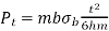
In gears, power is transmitted by means of a force exerted by the tooth of the driving gear on the meshing tooth of the driven gear denoted by PN in the figure 1.2.
Figure shows the components of the PN in redial direction denoted by Prand in tangential direction denoted by Pt.
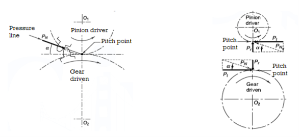
Figure 2 Force of gear tooth Figure 3 Components of tooth force
The tangential component Pt is a useful load because it determines the magnitude of the torque and consequently the power, which is transmitted.
Pris a separating force, which is always directed towards the center of the gear. The torque transmitted by the gears is given by,
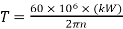 (1.3)
(1.3)
T = torque transmitted by gears (N-mm)
KW = power transmitted by gears (kW)
n = speed of rotation (rpm)
d= pitch circle diameter (mm).
Expression for different force acting on the gear tooth is shown in table 5
Table 5 Expression for different forces acting on gear tooth
Force | Expression |
Tangential force (Pt) |  |
Radial force (Pr) |  |
Resultant force (PN ) |  |
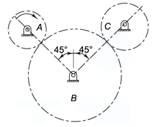
Q10) The pitch circles of a train of spur gears are shown in figure.Gear A receives 3.5 kW of power at 700 rpm through its shaft and rotates in the clockwise direction. Gear B is the idler gear while the gear C is the driven gear. The number of teeth on gears A, B and C are 30, 60 and 40 respectively, while the module is 5 mm. Calculate
(i) the torque on each gear shaft; and
(ii) the components of gear tooth forces.
Draw a free-body diagram of forces and determine the reaction on the idler gear shaft. Assume 20° involute system for the gears.
A10)
Given, kW = 3.5 kW, n = 700 rpm, ZA = 30
ZB = 60 ZC = 40 m = 5 mm a = 20°
Step I Torque acting on shafts A, B and C
dA = mZA = 5(30) = 150 mm
dB = m ZB = 5 (60) = 300 mm
dC = m ZC = 5(40) = 200 mm
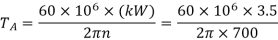
=47746.48 N-mm
Gear B is the idler gear and does not transmit any torque to its shaft. Therefore,
TB=0
Since the same power is transmitted from the gear A to the gear C,
TA×nA= TC×nC
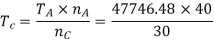
=63661 98 N-mm
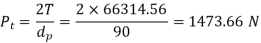
Step II Components of gear tooth forces The components of the gear tooth force between gears A and B are given by,
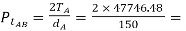 636.62 N

Since the gear B is the idler, whatever torque it receives from the gear A is transmitted to the gear C. Therefore,
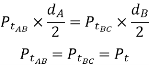
The tangential component between gears B and C must be equal to the tangential component between gears A and B. Since the tangential components are equal, the radial components ( ) must be equal.
Step III Free-body diagram of forces are drawn in the given figure
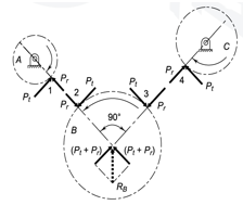
Fig 4. Free body diagram of forces
Step IV Reaction on idler gear shaft
From the free body diagram of B
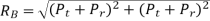
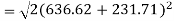 = 1228 N
Q11) Explain in brief beam strength equation.
A11)
The analysis of bending stresses in gear tooth was done by Wilfred Lewis, in his analysis gear tooth is treated as a cantilever beam shown in figure 1.4. And the cause of the bending stress is the tangential force Pt. Assumptions of the Lewis analysis are given below
- The effect of the radial component (Pr), which induces compressive stresses, is neglected.
- It is assumed that the tangential component (Pt) is uniformly distributed over the face width of the gear. This is possible when the gears are rigid and accurately machined.
- The effect of stress concentration is neglected.
- It is assumed that at any time, only one pair of teeth is in contact and takes the total load.
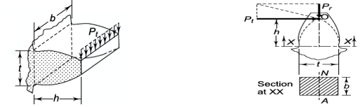
Figure 5 Gear tooth as cantilever beam Figure 6 Gear tooth as parabolic beam
Lewis also assume that the gear tooth has parabolic outline as shown in figure 1.5 so that it has uniform beam strength.
The weakest section of the gear tooth is at the section XX, where the parabola is tangent to the tooth profile.
Bending stress for a cantilever beam is given by the equation 1.4.


 (1.4)
(1.4)
Where, σb= bending stress
Mb=bending moment
I= area moment of inertia
t = thickness of the tooth
h = hight of the tooth
b= width of the tooth
After rearrangement of the equation we get

Multiplying the numerator and denominator of the right-hand side by m,
The above equation can be rewritten as
 (1.5)
(1.5)
Here, Y = Lewis form factor.
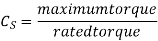
When the stress reaches the permissible magnitude of bending stresses, the corresponding force (Pt) is called the beam strength given by equation 1.5. This equation is known as the Lewis equation.
Where,
Pt = beam strength of gear tooth (N)
σb = permissible bending stress (N/mm2)
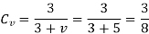
Q12) What is velocity factor?
A12)
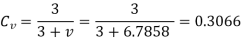
It is difficult to calculate the exact magnitude of dynamic load in the preliminary stages of gear design. To overcome this difficulty, a velocity factor Cv developed by Barth is used. The values of the velocity factor are as follows:
For ordinary and commercially cut gears made with form cutters and with v < 10 m/s,

For accurately hobbed and generated gears with v < 20 m/s,

For precision gears with shaving, grinding and lapping operations and with v > 20 m/s,

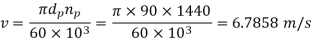
Where v is the pitch line velocity given by,

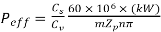
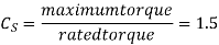
Q13) What is service factor?
A13)
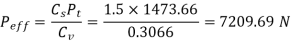
In gear design, the maximum force(due to maximum torque) is the criterion. This is accounted by means of a service factor. The service factor Cs is defined as
Q14) What is load concentration factor?
A14)
Load concentration factor
A pressure concentration, additionally called a pressure riser/raiser, is a factor in a element wherein the pressure is drastically more than its surrounding area. Stress concentrations arise because of irregularities with inside the geometry or with inside the cloth of a aspect shape that motive an interruption of the pressure flow. These interruptions generally get up from discontinuities consisting of holes, grooves, notches and fillets.
A discontinuity’s diploma of attention below traditional tensile masses is commonly expressed through the non-dimensional pressure attention factor (Kt), that's the ratio of the best pressure to the reference (some distance field) pressure:
K = ϭmax/ ϭref
Q15) Explain wear strength equation.
A15)
The analysis of wear strength was done by Earle Buckingham, he gave the equation which gives the wear strength of the gear tooth on the basis of Hertz theory of contact stresses. In Buckingham’s equation tangential force on the gear tooth is given by equation 1.6.
 (1.6)
(1.6)
Where
Pt= Tangential force,
b= face width,
Q= ratio factor, given by

dp= diameter of pinion
dg= diameter of gear
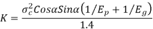
K= Load stress factor, given by
The value of tangential force given in equation 1.6 is known as the wear strength of the gear tooth.
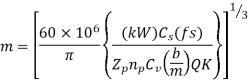
Q16) Explain estimation of module based on beam and wear strength
A16)
To calculate the module of the gear tooth we have to equate the effective load and the wear strength in from Buckingham’s equation
From Buckingham’s equation

Put dp=mZp
Where,
m = module
Zp= number of teeth on pinion
By multiplying and dividing by m in Buckingham’s equation, we get
 (1.7)
(1.7)
And effective load on the gear tooth is given by

From table 1.5
 (a)
(a)
Where

 (b)
(b)
Now from (a) and (b) we get
 (1.8)
(1.8)
By equating equation 1.7 and 1.8 we get

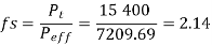
Fs= factor of safety
Q17) It is required to design a pair of spur gears with 20° full-depth involute teeth based on the Lewis equation. The velocity factor is to be used to account for dynamic load. The pinion shaft is connected to a 10 kW, 1440 rpm motor. The starting torque of the motor is 150% of the rated torque. The speed reduction is 4: 1. The pinion as well as the gear is made of plain carbon steel 40C8 (Sut = 600 N/mm2). The factor of safety can be taken as 1.5. Design the gears, specify their dimensions.
A17)
Given, kW = 10, n = 1440, rpm i = 4, Sut = 600 N/mm2, (fs) = 1.5,
Starting torque = 150% (rated torque),
The Lewis form factor Y = 0.308 for 18 teeth.
Step I Estimation of module based on beam strength
Since both gears are made of the same material, the pinion is weaker than the gear. The minimum number of teeth for 20° pressure angle is 18. Therefore,
Zp = 18
Zg = iZp = 4(18) = 72

Y = 0.308
The velocity factor is unknown at this stage. Assuming a trial value for the pitch line velocity as
5 m/s,
It is assumed that the ratio (b/m) is 10. By using following relation
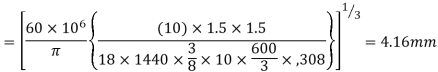
Step II Selection of module
The first preference value of the module is 5 mm.
Trial 1
m = 5 mm
dp = mZp = 5(18) = 90 mm
dg = mZg = 5(72) = 360 mm
b = 10 m = 10(5) = 50 mm
Check for design
Using Lewisequation

The design is satisfactory and the module should be 5 mm.
Q18) Explain estimation of dynamic tooth load by velocity factor and Buckingham’s equation
A18)
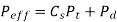
The dynamic load is calculated by equations derived by Earle Buckingham. The effective load is given by,
Where Pd= incremental dynamic load, given by
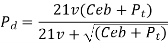
v = pitch line velocity (m/s)
C = deformation factor (N/mm2)
e = sum of errors between two meshing teeth (mm)
b = face width of tooth (mm)
Pt = tangential force due to rated torque (N)
Deformation factor C is given by

Where,
k = constant depending upon the form of tooth
Ep = modulus of elasticity of pinion material (N/mm2 )
Eg = modulus of elasticity of gear material (N/mm2 )
Q19) What is AGMA?
A19)
AGMA (American Gear Manufacturing Association) approach of Gear design (Only mathematical relations, no numerical)
- The American Gear Manufacturers Association (AGMA) is a voluntary affiliation of businesses, consultants, and academicians with a right away hobby with inside the design, manufacture, and alertness of gears, couplings and associated electricity transmission additives and equipment.
- Founded in 1916, AGMA is a member- and marketplace-pushed organization, engaging in applications and offering offerings to the tools enterprise and its customers. AGMA member businesses presently quantity greater than 495.
- They encompass tools producers from the United States, Mexico, and Canada, in addition to gearing hobbies from greater than 30 nations across the world. AGMA is authorized with the aid of using the American National Standards Institute to write down all U.S. Requirements on gearing.
- AGMA is likewise the Secretariat (Chairman) for Technical Committee 60 of the International Organization for Standardization (ISO). TC 60 is the committee chargeable for growing all global gearing requirements. In addition to the keeping the location of Secretariat, AGMA convenes (chairs) the energetic ISO Working Groups associated with tools inspection and testing.
- AGMA started at the slicing aspect of latest technologies. In 1916, a brand new tools marketplace changed into emerging. It emphasised quiet operation, especially for timing gears with inside the automobile enterprise. Gear producers had been exploring numerous materials – however lacked technical requirements for non-metal gearing.
- AGMA changed into born whilst R.D. Nuttall Company added collectively numerous tools producers to talk about growing such requirements. The first AGMA individuals covered Cincinnati Gear Company, Earle Gear and Machine Company, Horsburgh and Scott Company, Newark Gear Cutting Machine Company, R.D. Nuttall Company, Philadelphia Gear Works, Pittsburgh Gear and Machine Company, Simonds Manufacturing Company and Van Dorn Dutton Company.
Q20) What is helical gear?
A20)
Teeth of these gears are cut at an angle with the shaft axis shown in figure 2.1. Similar to spur gears these gears also have involute teeth. The magnitude of helix angle for both gear and pinion is same and the hand of the helix is opposite. These gears impose radial and thrust forces on the shafts.
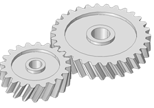
Figure 7 helical gears
Types of helical and Bevel Gears
There are two basic types of helical gears, parallel and crossed.
Parallel helical gearsIn these gears magnitude of the helix angle is the same for the pinion and the gear, however, the hand of the helix is opposite. A righthand pinion meshes with a left-hand gear and vice versa.
Crossed helical gears are mounted on shafts with crossed axes. Their teeth may have the same or opposite hand of the helix.
Terminology of helical gears
Helix angle (ψ) It is defined as the angle between the axis of the shaft and the centre line of the tooth taken on the pitch plane.
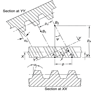
Figure 8. Tooth Relationships
Transverse circular pitch (p) The distance A1A2 in figure 2.2 is called the transverse circular pitch (p), which is measured in the plane of rotation.
Normal circular pitch (pn) The distance AC1 in figure 2.2 is called the normal circular pitch (pn), which is measured in a plane perpendicular to the tooth elements.


From above expression, We get

Where Pn and P are normal and transverse diametral pitches respectively.
Using P=1/m, we get
We get, 
Where,
mn = normal module (mm)
m = transverse module (mm)
Axial pitch (pa) In figure 2.2in triangle A1A2B2 the distance A1B2 represents the axial pitch, which is given by the following formula.

Transverse pressure angle (α) Pressure angle in transverse plane is known as the transverse pressure angle.
Normal pressure angle (αn) Pressure angle in normal plane is known as the normal pressure angle.
Relation between transverse and normal pressure angle is given by following equation.

Pitch circle diameter (d) Pitch circle diameter of helical gear is calculated by the following relation,

Where, z= number of teeth on the gear.
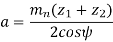
Central distance (a) The centre to centre distance a between the two helical gears having zl and z2 as the number of teeth is given by,
Virtual number of teeth
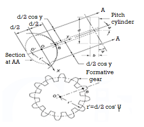
Figure 9. Formative Gear
In the design of helical gears, an imaginary spur gear is considered in the plane A–A with centre at O’ having a pitch circle radius of r’ and module mn. It is called a ‘formative’ or ‘virtual’ spur gear as shown in figure 2.3. The pitch circle diameter d¢ of the virtual gear is given by,

The number of teeth z’ on this imaginary spur gear is called the virtual number of teeth. It is given by


