Unit - 2
Meshing Techniques
Q1) What is meshing technique?
A1)
Mesh era is the exercise of making a mesh, a subdivision of a non-stop geometric area into discrete geometric and topological cells. Often those cells shape a simplified complex. Usually the cells partition the geometric enter area.
Mesh cells are used as discrete neighborhood approximations of the bigger area. Meshes are created through laptop algorithms, regularly with human steerage via a GUI, relying at the complexity of the area and the kind of mesh desired.
The aim is to create a mesh that appropriately captures the enter area geometry, with high-quality (well-shaped) cells, and without such a lot of cells as to make next calculations intractable. The mesh must additionally be fine (have small factors) in regions which are vital for the following calculations.
- Meshes are used for rendering to a laptop display screen and for bodily simulation which include finite detail evaluation or computational fluid dynamics.
- Meshes are composed of easy cells like triangles because, e.g., we realize the way to carry out operations which include finite detail calculations (engineering) or ray tracing (laptop pics) on triangles, however we do now no longer realize the way to carry out those operations immediately on complex areas and shapes which include a roadway bridge.
- We can simulate the electricity of the bridge, or draw it on a laptop display screen, through appearing calculations on every triangle and calculating the interactions among triangles.
- A fundamental difference is among based and unstructured meshing.
- In based meshing the mesh is a everyday lattice, which include an array, with implied connectivity among factors. In unstructured meshing, factors can be linked to every different in abnormal patterns, and extra complex domain names may be captured.
- This web page is more often than not approximately unstructured meshes. While a mesh can be a triangulation, the procedure of meshing is outstanding from factor set triangulation in that meshing consists of the liberty to feature vertices now no longer gift with inside the enter.
- "Faceting" (triangulating) CAD fashions for drafting has the identical freedom to feature vertices, however the aim is to symbolize the form appropriately the use of as few triangles as feasible and the form of person triangles isn't vital.
- Computer pics renderings of textures and sensible lighting fixtures situations use meshes instead. Many mesh era software program is coupled to a CAD machine defining its enter, and simulation software program for taking its output.
- The enter can range significantly however not unusual place paperwork are Solid modeling, Geometric modeling, NURBS, B-rep, STL or a factor cloud.
Q2) Define discretization of a structure.
A2)
Discretization refers back to the system of translating the cloth area of an object-primarily based totally version into an analytical version appropriate for analysis.
In structural analysis, discretization can also additionally contain both of simple analytical-version types, including: Node-detail version, wherein structural factors are represented with the aid of using man or woman strains linked with the aid of using nodes. In a 3-d system, every node has six levels of freedom, every both restrained or free.
The geometric and cloth homes of structural factors are then characterized with the aid of using line factors which simulate their bodily conduct with the aid of using following mathematical relationships.
Through utility of the direct stiffness method, loading at node places interprets into displacement and pressure fields which suggest structural performance.
Finite-detail version, wherein a meshing manner creates a community of line factors linked with the aid of using nodes inside a fabric continuum.
Each line detail simulates the geometric and bodily homes of the nearby cloth. Given the loading and boundary situations of the entire system, numerical system of structural reaction can also additionally improve thru the computational version.
The discretization of a finite-detail version could have a few diploma of refinement, generating both a rough or first-rate mesh. A node-detail version is technically a finite-detail version wherein an unmarried line detail represents the structural detail.
Node-detail modeling, however, follows the direct stiffness method, while finite-detail modeling follows the finite-detail method (FEM).
Q3) What is division of body factors?
A3)
While the discretization of an object-primarily based totally version is continually critical (in that discretization allows evaluation), there are situations wherein it's also crucial to divide body factors into more than one segments such that correct consequences are generated. It is beneficial to subdivide body factors for the subsequent evaluation types: Buckling evaluation - To seize better modes.
Dynamic evaluation - To higher seize mass distribution, due to the fact that mass is assembled at joint places.
P-Delta (P-δ) effect - To higher seize neighborhood column deformation for evaluation of equilibrium situations approximately displaced configuration.
Displacement accuracy - To create joints at places in which correct displacements are needed, in any other case values are interpolated from the nodes at both quit of the body element.
Q4) What is1D GEOMETRIES and Modeling? Give advantages of same.
A4)
1D GEOMETRIES
The mesh generator discretizes the domain names (intervals) into smaller intervals (or mesh factors). The endpoints of the mesh factors are known as mesh vertices. The limitations (or vertices) described with inside the geometry are represented with inside the mesh with the aid of using boundary factors (or vertex factors).
Modeling:
The form of 1D detail is line that's created with the aid of using becoming a member of nodes. So the duration is described with the aid of using modeling line even as different measurement are described with the aid of using assigning respective pass sections to the line. Likewise 1D detail is modeled in FEA. FEA software program codes consists of many trendy pass sections along with C Channel, I beam, rectangular, square, circular & hole phase or even consumer described phase too.
Practical Examples:
Long shafts, pin joints, connection elements, etc.
Advantages:
Solution computing is faster: Only one detail throughout pass phase examine to 2D and 3-d elements, consequences good sized discount in mesh count & answer time.
Less efforts for modeling and meshing
Design modifications are easier: Just want to alternate the pass phase of the (beam elements)
Fruitful for automation and layout codes: There are lot of codes and layout pointers publications on beam layout
Q5) What is 2D GEOMETRIES?
A5)
The mesh generator discretizes the domain names into triangular or quadrilateral mesh factors. If the boundary is curved, those factors constitute an approximation of the unique geometry. The facets of the triangles and quadrilaterals are known as mesh edges, and their corners are mesh vertices. A mesh part have to now no longer comprise mesh vertices in its interior. The limitations described with inside the geometry are discretized (approximately) into mesh edges, known as boundary factors (or part factors), which have to conform to the mesh factors of the adjoining domain names. The geometry vertices are represented with the aid of using vertex factors.
Modeling:
2D shapes are plate shape for which mid surface is extracted and thickness is assigned on each the facet of the floor (1/2 of thickness on both sides). Moreover, occasionally pinnacle and backside floor are extracted and respective thickness is assigned (For pinnacle floor backside facet whilst for backside floor pinnacle facet thickness is assigned in order that actual geometry form is represented).
Practical Example:
Thin vessels, sheet steel parts, plastic additives like instrumental panels, etc. Generally 2D meshing is used whilst width to thickness ratio is extra than 20. The Pitfalls:
Advantages
1D factors in phrases of much less modeling efforts and quicker simulation evaluate to three-D Elements.
Have challenge whilst irregular floor with extraordinary capabilities on sides.
Difficulties to peer stresses throughout thickness like in case of pressure linearization method for strain vessels.
Q6) Define 3-D GEOMETRIES
A6)
The mesh generator discretizes the domain names into tetrahedral, hexahedral, prism, or pyramid mesh factors whose faces, edges, and corners are known as mesh faces, mesh edges, and mesh vertices, respectively.
Modeling:
Tetra, Penta, Hex, Pyramid are the broadly speaking detail form used to outline the 3-D elements. If geometry is sweep able or maple (as an instance shell in case of vessel) then Hex mesh is favored in any other case tetra mesh is used. For all abnormal shapes tetra mesh is used. If the shape is having sweep able in addition to abnormal shapes in such state of affairs the aggregate of hex, tetra and pyramid or penta in among is used.
Practical Examples:
Industrial valves, Casing, engine block, connecting rods, etc (maximum of actual existence items are solids).
Q7) Define refining Mesh.
A7)
This statistics permits the prediction of real-international behavior, frequently with very excessive stages of accuracy. The accuracy that may be acquired from any FEA version is without delay associated with the finite detail mesh this is used.
- The finite detail mesh is used to subdivide the CAD version into smaller domain names referred to as factors, over which a fixed of equations are solved.
- These equations about constitute the governing equation of hobby thru a fixed of polynomial features described over every detail.
- As those factors are made smaller and smaller, because the mesh is refined, the computed answer will technique the actual answer.
- The Mesh Refinement Process A correct finite detail analyst begins off evolved with each an information of the physics of the machine this is to be analyzed and a whole description of the geometry of the machine.
- This geometry is represented thru a CAD version.
- A ordinary CAD version will correctly describe the form and structure, however frequently additionally include beauty capabilities or production info that may show to be extraneous for the functions of finite detail modeling.
- The analyst must place a few engineering judgment into inspecting the CAD version and identifying if those capabilities and info may be eliminated or simplified previous to meshing.
- Starting with an easy version and including complexity is sort of continually less difficult than beginning with a complicated version and simplifying it.
- The analyst must additionally recognize all the physics which can be applicable to the problem, the substances homes, the masses, the constraints, and any factors that may have an effect on the consequences of hobby.
- These inputs may also have uncertainties in them. For instance, the cloth homes and masses won't continually be exactly known. It is essential to hold this in thoughts all through the modeling manner, as there may be no advantage in looking to clear up a version to extra accuracy than the enter records admits.
Q8) Give the mesh refinement process.
A8)
A accurate finite element analyst starts off evolved off evolved with every an records of the physics of the gadget that is to be analyzed and an entire description of the geometry of the gadget.
A everyday CAD model will effectively describe the shape and structure, but regularly moreover encompass splendor talents or manufacturing information that can display to be extraneous for the features of finite element modeling.
The analyst ought to locate some engineering judgment into analyzing the CAD model and figuring out if the ones talents and information can be removed or simplified preceding to meshing.
Starting with a clean model and which include complexity is kind of usually much less tough than starting with a complex model and simplifying it. The analyst ought to moreover understand all of the physics which may be relevant to the problem, the materials houses, the hundreds, the constraints, and any elements that can have an impact at the results of interest.
Q9) What is the effect of mesh density in critical region, use of symmetry?
A9)
The have a look at confirmed that after the mesh length of the detail is reduced, the simulated result gets closer to the experimental result at initial simulation with a default mesh length, and an mistakes of 16. 39% turned into detected in comparison to the experimental.
As the detail length is reduced the mistake additionally diminishes as much as while the mesh length offers the same result as the experimental.
This shows the extremely good have an impact on of mesh length at the simulation evaluation of cross-rail. The have a look at additionally confirmed that the smaller the detail length, the better the useful resource requirement.
Application of FEA in the investigation strain concentration under numerous loading conditions turned into carried out via way of means of numerous researchers and the research confirmed that the choice of the right length of the mesh is vital to any FEA simulation results.
The preceding research have proven that fashions with smaller (or finer) detail sizes yield more accurate results but requires longer computational time as in comparison with larger (or coarse) detail fashions with less accurate results and commonly have a shorter computing time.
Furthermore, research additionally pointed clearly out, that the computation time and the accuracy of any FEA have a look at largely depend on mesh density (More &Bindu, 2015.,&Dutt, 2015).
Therefore, the intention of this this have a look at is to research the impact of mesh detail length and density on finite detail evaluation simulation of a simple assist bracket.
Q10) Give use of Symmetry of mesh refining process.
A10)
The symmetry boundary situation defines a replicate face/surface. It ought to best be used if the bodily item or geometry and the predicted go with the drift subject sample of the evolved answer are reflected alongside that surface.
- By the usage of this boundary situation, the area can basically be halved, lowering the time to obtain an answer.
- In detail, the symmetry situation applies the subsequent constraints at the go with the drift variables: The fluxes throughout the symmetry are zero.
- The ordinary additives of all variables are set to zero. It may be implemented to each planar or non-planar faces/surfaces at the area boundaries this boundary situation is used to use replicate-symmetry situations on a shape.
- It may be implemented to faces of a shape and no different person enter is needed. If a symmetry aircraft situation is implemented to a face, the displacement of this face is locked in an ordinary path however loose to slip in tangential directions.
- This boundary situation is especially beneficial while the symmetry aircraft isn't aligned with any worldwide coordinate axis.
Q11) Give element Quality Criteria: Jacobian
A11)
The floor mesh have to have a most of close to 1.00. If the version famous factors with values with inside the hundred or lots those are terrible factors. A cost of 1.four can be acceptable, but a cost under 2 most can be allowable. (The top restriction calls for verification via way of means of the consumer to set up an exceptional practice).
An excerpt from an MSC assist section: Jacobian Ratio The ratio of the most determinant of the Jacobian to the minimal determinant of the Jacobian is calculated for every detail with inside the modern institution with inside the energetic viewport.
This detail form take a look at may be used to become aware of factors with indoors nook angles a long way from ninety stages or excessive order factors with out of place midsize nodes. A ratio near or same to 1.zero is desired.
- This is as technical as engineering comes. Bring up a Jacobian to a group of finite detail engineers and optimistically they may all realize what you're speaking about.
- This is so technical that it generally most effective blanketed in senior stage university lessons or graduate faculty lessons.
- Although, in case you do cowl it in university you'll probably do the real matrix equations, despite the fact that in actual life (the enterprise world) a pc does it in fractions of a second. Now greater especially the Jacobian, which is brief for the Jacobian Matrix Determinate, is absolutely the nice degree of finite detail mesh first-rate.
- It is one quantity which defines how precise or horrific a detail is. The Jacobian is a degree of the normal of the detail faces relative to every other.
- Unfortunately, hyper mesh does now no longer display the detail face normal on stable elements, however it is largely an arrow on every face declaring perpendicular to the face.
- The variety of a Jacobian is from 1, an ideal dice, to something lower, -1 or maybe lower.
- The smallest Jacobian I even have visible was -1.45. When the detail face normal begin to cross, this is they're now no longer perpendicular to every other, your detail first-rate receives worse.
- For numerous examples I created the picture below. In all the elements, besides for the crimson one, I definitely translated one node (vertex) to a brand new vicinity and saved the alternative seven with inside the authentic dice positions.
Q12) Give various terminology used in Meshing Techniques.
A12)
Aspect ratio:
Aspect ratio is the degree of a mesh element's deviation from having all aspects of identical length. An excessive factor ratio takes place with long, skinny factors. Entering an excessively massive fee for the Minimum Element Size mesh manage might also additionally purpose the mesh generator to create stable factors with excessive factor ratios. Cero Simulate calculates factor ratio, R, in keeping with this formula:
R = E/h
Where E is the longest edge and h is the shortest height—the distance between a vertex and the opposite surface or edge.
Return to Checking a FEM Mesh.
Aspect Ratio Calculation for Triangular Element:
Aspect ratio:
The ratio among longest fringe of an detail to both its shortest side or the shortest distance from a nook node to the opposing side is referred to as Aspect Ratio.
Aspect ratio = Large Edge length / Minimum L
Minimum Length:
Hyper mesh makes use of the subsequent 3 techniques to calculate minimal duration.
Minimal Normalized Height (MNH):
Find the perpendicular distance from every node to its contrary aspect (hi, hj&hk). Hence, the MNH is minimal of (hi, hj&hk) accelerated with the aid of using scaling component [2/√3] (scaling component guarantees that for Equilateral triangle MNH is equal because the minimal aspect duration).
Aspect Ratio Calculation for Quadrilateral Element:
Aspect ratio: The ratio between longest edges of an element to either its shortest edge or the shortest distance from a corner node to the opposing edge is called Aspect Ratio.
Aspect ratio = Longest Edge Length / Minimum Length
Minimum Length:
Hyper mesh uses the following techniques to calculate minimum length. The shortest aspect (in which the length of the shortest aspect of each element is used). The minimal normalized height (this is more accurate, but more complex).
Minimal normalized height (MNH):
For each corner node, draw perpendicular line to the alternative sides which are not containing that node. With respect to the figure, from node “j” draw perpendicular traces to sides “lj&lk” as shown. Measure the lengths “hj1 & hj2”. Similarly, Repeat the above approach for all specific nodes (I, k & l) and find out their lengths (average 8 Lengths).
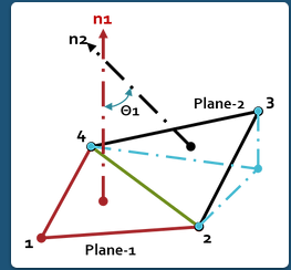
Warpage and minimum and maximum angles:
Warping of an Element:
Ideally all of the nodes of quadrilateral detail ought to lie at the identical aircraft however at curvatures and complex geometry profiles it isn't possible. "Measure of out of planeness of a Quadrilateral is Warping Factor or Warping Angle". Warping calculation for triangular factors isn't applicable, considering the fact that 3 factors outline a aircraft, this test most effective applies to quads.
Q13) What is warping angle and warping factor?
A13)
Warping Angle:
Maximum Angle out of the 2 opportunities is mentioned as "Warp Angle". In the case of strong factors, a detail's face deviates from being planar. The quad is split into tries alongside its diagonal, and the attitude among the tries normal is measured.
Ideal Value = 0° ( Acceptable < 5° to 10°) Assume a Quad detail is fashioned with Nodes:1,2,3 &4 Split the Quad the usage of the 2 diagonals (1,3 & 2,4) into triangles as proven below.
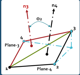
Warping Factor:
Some of the Finite Element Software’s calls the Out of Planeness of a detail as Warping Factor rather than Warping Angle. Ideal cost of Warping Factor=zero (Acceptable: zero to 1) Warping Factor is calculated with the aid of using the subsequent procedure: Find the not unusual place Normal to the 2 diagonals (Vectors) AC & BD with vector go product or with the aid of using the usage of 3D-Geometry principles. Then generate planes perpendicular to not unusual place Normal and passing thru A, C and B, D.
These planes containing AC in a single aircraft BD in different aircraft are parallel to every different.
Q14) What is construct an Average Plane among those planes?
A14)
Construct an Average Plane among those planes.
The projection of Nodes in this common aircraft are A’B’C’ and D’ respectively and it bureaucracy A’B’C’D’ Quadrilateral.
The distance of Nodes from Average aircraft is equal i.e., AA’=BB’=CC’=DD’=h Now, locate the distinction in of heights of nodes of Edge with appreciate to Average aircraft.
Difference in Nodal peak of Edge AB is h-(-h) =2h (Distance among parallel planes).
Find the area (A) of the Quadrilateral (A’B’C’D’) fashioned at the Avg. Plane with the projections of Actual Nodes (A, B, C and D).
The Warping Factor is the Ratio among the Distance of Nodes with inside the course of Avg. Normal (2h) and Square root of the Area of the Element projected directly to the Avg.
Normal Plane √A. So, the Warping Factor= 2h/√A for a flat Quadrilateral, h=zero. So, Warping Factor=zero.
Q15) What is the average element size?
A15)
Average element size:
One of the maximum not unusual place questions you’ll listen requested with inside the FEA network is “What mesh length must I use?”, and for proper reason! If your mesh is simply too coarse, the solutions which you generate might not be as correct as you want them to be.
Conversely, in case your mesh is simply too fine, the simulation will take a great deal longer to run without imparting any vast development in accuracy.
In this blog, though, we are able to discover a pair of various techniques that may be used to assist decide the ideal detail length so that it will offer correct consequences efficiently.
To do this, absolutely run your version with numerous distinct mesh sizes and plot the ensuing strain or displacement values. Your mesh length is taken into consideration to have “converged” while there may be little determined alternate in strain or displacement price with reducing mesh length.
To exhibit a mesh sensitivity analysis, we've got simulated a cantilevered metallic rod the usage of 4 distinct hexahedral (C3D8I) meshes. The expected values for strain and displacement are provided, in conjunction with the desired computational time for every simulation.
- First, though, hand calculations may be executed to decide the predicted values for strain and displacement.
- Calculation parameters and answers are proven with inside the desk below: The predicted displacement primarily based totally handy calculations is 0.4244 mm. As we will see from this study, as mesh length decreases, the most displacement converges closer to the calculated price.
- However, it must be referred to that the run time grows exponentially and affords diminishing marginal returns in phrases of answer accuracy, as proven below.
- Because the most strain values displayed above had been measured from a node barely distant (0.16L) from the constant give up of the cantilevered beam, the calculated guide strain used for evaluation should be corrected, which ends up in a calculated strain price of 213. NineMPa (in preference to 254.7 MPa).
- Stresses had been measured at this region to keep away from any synthetic strain awareness outcomes imposed with the aid of using the boundary situation on the constant give up of the beam. As mesh length decreases, the most important strain values converge closer to the calculated price.
- Also really well worth noting is that hexahedral factors are commonly now no longer the maximum suitable factors to apply in simulations regarding bending on the grounds that they're susceptible to shear locking.
- This impact may be really mitigated thru mesh refinement, however a higher answer is to apply C3D8I factors, which use an advanced system meant to higher seize such behavior.
Q16) What is minimum length?
A16)
Minimum Length:
In pc science, excellent, worst, and common instances of a given set of rules explicit what the aid utilization is at least, at maximum and on common, respectively. Usually the aid being taken into consideration is going for walks time.
- Best case is the characteristic which plays the minimal wide variety of steps on enter information of n elements. Worst case is the characteristic which plays the widest variety of steps on enter information of length n.
- Average case is the characteristic which plays a mean wide variety of steps on enter information of n elements. In real-time computing, the worst-case execution time is regularly of unique challenge in view that its miles crucial to understand how plenty time is probably wished with inside the worst case to assure that the set of rules will usually end on time.
- Average overall performance and worst-case overall performance are the maximum utilized in set of rules evaluation.
- Less extensively discovered is excellent-case overall performance, however it does have uses: as an instance, wherein the excellent instances of person obligations are known, they may be used to enhance the accuracy of a usual worst-case evaluation.
- Computer scientists use probabilistic evaluation techniques, mainly predicted value, to decide predicted going for walks times.
- The phrases are utilized in different contexts; as an instance the worst- and excellent-case final results of an epidemic, worst-case temperature to which a digital circuit detail is exposed, etc.
- Where additives of particular tolerance are used, gadgets should be designed to paintings well with the worst-case aggregate of tolerances and outside conditions.
Q17) What do you mean by skewness?
A17)
Skewness:
Skewness refers to a distortion or asymmetry that deviates from the symmetrical bell curve, or regular distribution, in a hard and fast of statistics. If the curve is shifted to the left or to the proper, its miles stated to be skewed.
Skewness may be quantified as an illustration of the volume to which a given distribution varies from a regular distribution. A regular distribution has a skew of 0, even as a lognormal distribution, for example, might showcase a few diploma of proper-skew.
Besides advantageous and poor skew, distributions also can be stated to have 0 or undefined skew. In the curve of a distribution, the statistics at the proper facet of the curve may also taper in a different way from the statistics at the left facet.
These tapering’s are called "tails. Negative skew refers to an extended or fatter tail at the left facet of the distribution, even as advantageous skew refers to an extended or fatter tail at the proper.
- The suggestion of undoubtedly skewed statistics could be extra than the median. In a distribution this is negatively skewed, the complete opposite is the case: The suggestion of negatively skewed statistics could be much less than the median.
- If the statistics graphs symmetrically, the distribution has 0 skewness, irrespective of how lengthy or fats the tails are.
- The 3 chance distributions depicted beneath are undoubtedly-skewed (or proper-skewed) to a growing diploma.
- Negatively-skewed distributions also are called left-skewed distributions. There are numerous methods to degree skewness.
- Pearson’s first and 2d coefficients of skewness are not unusual place ones. Pearson’s first coefficient of skewness, or Pearson mode skewness, subtracts the mode from the suggestion and divides the distinction with the aid of using the usual deviation.
- Pearson’s 2d coefficient of skewness, or Pearson median skewness, subtracts the median from the suggestion, multiplies the distinction with the aid of using 3, and divides the product with the aid of using the usual deviation.
Q18) Write a note on tetra Collapse.
A18)
- More than 75% of the Earth's land location is with inside the northern hemisphere. Continents are more or less triangular.
- Oceans are more or less triangular. The North Pole is surrounded with the aid of using water, the South Pole with the aid of using land. Exactly contrary the Earth from land is sort of usually water.
- To recognize its appeal, remember the "normal solids": the field and the 5-member set of Platonic Solids.
- The strong with the bottom variety of aspects is the tetrahedron (4 equilateral triangles); progressing via the hexahedron or cube, the octahedron, the dodecahedron and the icosahedron (20 aspects), the field may be taken into consideration to have a countless variety of aspects. All six normal solids percentage many symmetries.
- Now, for every normal strong, we may also relate its floor location and quantity with the aid of using the equation:
- As we traverse the set so as of growing variety of faces, we discover that ok will increase for every member; it's far 0.0227 for a tetrahedron and 0.0940 for a sphere.
- Thus the tetrahedron is the normal strong with the biggest floor location for a given quantity, and makes an inexpensive endpoint for a shrinking round Earth.


