Unit - 1
Elemental properties
Q1) Give introduction to Computer Aided Engineering (CAE)
A1)
Computer-aided engineering (CAE) is using pc software program to simulate overall performance with a purpose to enhance product designs or help with inside the decision of engineering issues for an extensive variety of industries. This consists of simulation, validation and optimization of products, processes, and production tools.
CAE packages guide an extensive variety of engineering disciplines or phenomena.
- Stress and dynamics evaluation on additives and assemblies the use of finite detail evaluation (FEA)
- Thermal and fluid evaluation the use of computational fluid dynamics (CFD)
- Kinematics and dynamic evaluation of mechanisms (multimode dynamics)
- Acoustics evaluation the use of FEA or a boundary detail method (BEM)
- 1D CAE, or mechatronic device simulation, for multi-area mechatronics device layout Mechanical occasion simulation (MES)
- Control structures evaluation Simulation of producing techniques like casting, molding and die press forming Optimization of the product or procedure
Q2) Give benefits of CAE.
A2)
- The blessings of CAE consist of decreased product improvement price and time, with advanced product pleasant and durability.
- Design choices may be made primarily based totally on their effect on overall performance.
- Designs may be evaluated and delicate the use of pc simulations in preference to bodily prototype testing, saving cash and time.
- CAE can offer overall performance insights in advance with inside the improvement procedure, whilst layout adjustments are much less steeply-priced to make.
- CAE facilitates engineering groups manipulate threat and apprehend the overall performance implications in their designs.
- Integrated CAE records and procedure control extends the capacity to correctly leverage overall performance insights and enhance designs to a broader community.
- Warranty publicity is decreased with the aid of using figuring out and disposing of capacity problems.
- When well included into product and production improvement, CAE can permit in advance hassle resolution, which could dramatically lessen the prices related to the product lifecycle.
Q3) Write the importance of CAE.
A3)
Computer Aided Engineering (CAE) is a quick rising discipline that takes CAD to any other level.
While CAD is beneficial in developing 2D and three-D fashions of a product, CAE software program lets in a deeper engineering evaluation of gadgets.
CAE as a result unearths programs in engineering fields like fluid dynamics, kinematics, strain evaluation, finite detail evaluation, etc., generally in which product improvement is concerned.
CAE encompasses now no longer best CAD, however additionally Computer Aided Manufacturing (CAM), Finite Element Analysis (FEA), Computational Fluid Dynamics (CFD) and a few different elements of engineering.
Simply put, you could create 2D and three-D gadgets the use of CAD, at the same time as you could examine how that item will behave the use of CAE gear.
The automatic layout gear furnished via way of means of CAE have converted engineering evaluation from an ‘arms on’ revel in to digital simulation.
The CAE Process In the primary stage, the item / product / machine is designed, generally the use of CAD software program.
Engineers control the parameters of the item / machine being evaluated. These parameters encompass the bodily properties, geometry and the restrictions below which the entity is to be developed. In the second one stage, the entity is very well evaluated the use of CAE methods like FEA, NVH (noise, vibration and harshness), CFD, etc.
As a 3rd step, the outcomes are proven to the engineering layout crew and the parameters of the machine / item are tweaked to get optimal outcomes. The system is iterated until the favored blessings are achieved.
Q4) What is the use of CAE in Product development?
A4)
In the past, the bulk of layout verification for the duration of product improvement got here from bodily prototype checking out. An analytical method counting on engineering judgment turned into carried out to evolving designs the usage of properly understood, time demonstrated substances. Make a prototype, take a look at it out, and then make modifications primarily based totally at the take a look at outcomes. This make-&-smash method has its advantages–it’s the actual deal, amongst others.
Over time, designs and substances have end up an increasing number of complicated. Initiatives like non-stop fee improvement, light-weighting and optimization have placed more needs on product overall performance, and as a result, on layout and engineering. Today, mechanical engineers have the posh of having the ability to research and are expecting product overall performance the usage of the superior talents of CAE (Computer Aided Engineering) equipment to satisfy particular product overall performance requirements.
Designers and engineers want to apprehend the bodily behaviors of a complicated object. They additionally want to be expecting the overall performance of the layout, calculate the protection margin, and as it should be pick out weaknesses with inside the layout. The quit intention is to expectantly pick out appropriate or maybe advanced designs and substances for every precise product.
Through using Finite Element Analysis (FEA) and Computational Fluid Dynamics (CFD), together called CAE, this intention can commonly be accomplished in much less time and at a decrease fee than with conventional prototyping alone. Accuracy in those approaches has increased. Simulated checking out receives correlated to bodily checking out on the material, factor and gadget levels.
Development fee is reduced. When CAE is carried out early with inside the layout cycle, layout is guided with inside the proper course early with inside the procedure, while errors are costliest. Once a digital version has been correlated to bodily prototypes and tests, the layout crew could make changes and simulate checking out on the ones changes with ease, while not having to bodily construct and take a look at every new layout. This avoids highly-priced construct costs.
FEA has end up a way to the project of predicting layout flaws, indicating exactly wherein trouble regions exist because of immoderate strain or fatigue. Time to marketplace is reduced. This avoids making modifications overdue with inside the layout procedure, while modifications take longest to implement.
As the layout progresses, simulated checking out with CAE software program is completed in a fragment of the time it takes to construct and take a look at a bodily prototype. Physically coping with material & system and putting in place checking out labs is extra time consuming.
Often, operations carried out for the duration of the checking out procedure are repetitive, requiring mild changes to enter information earlier than re-going for walks a take a look at. In the CAE environment, automation of those repetitive iterations coupled with excessive overall performance computing (HPC) considerably reduces checking out times.
CAE evaluation outcomes are less complicated to apprehend, when you consider that they're displayed with excessive impact, 3-D, dynamic imaging. And, conversation is better with the aid of using hastily and as it should be sharing information among departments and throughout distances.
CAE software program has modified the arena of product layout and engineering. Through outsourcing, the effective blessings of CAE offerings and software program can now be loved with the aid of using businesses generating bodily merchandise in each enterprise sector.
Q5) Write a note on discretization methods
A5)
Discretization strategies are used to cut a non-stop function (i.e., the actual way to a gadget of differential equations in CFD) right into a discrete function, wherein the answer values are described at every factor in area and time.
Discretization without a doubt refers back to the spacing among every factor for your answer area. When a simulation intends to calculate a dynamic way to a fluid/warmth waft multiphasic trouble, the finite-distinction time-domain (FDTD) approach is used as we want to discretize time similarly to area. In 1D, 2D, or 3-d structures without time dependence (i.e., the steady-country answer), the finite detail approach (FEM) is used for discretization.
An opportunity approach for 3-d structures is the finite quantity approach (FVM), wherein the gadget is discretized in gadgets of quantity in place of as units of factors forming a mesh. Solution algorithms produce various convergence and are most effective adaptable to positive discretization strategies.
The maximum not unusual place answer strategies include: Iterative strategies: Picard, Newton, Newton-Raphson, and Uzawa strategies are the not unusual place strategies used to linearize structures of CFD equations and clear up their finite distinction equations. These linearization schemes are just like small-sign evaluation for circuit simulations.
Eulerian approach: This may be used to clear up the linearized Navier-Stokes equations for in viscid fluids and produces effects which might be in large part equal to iterative strategies for in viscid fluids. Network strategies: This includes defining distinct areas with distinct cloth homes in a gadget as factors in a community, wherein the interface among community factors is the spatial boundary among neighboring areas.
An associated method is the additive Schwartz method, which splits a CFD trouble into a couple of boundary price issues in distinct domain names and provides up the effects. Transformation strategies: These are linearization strategies which might be most effective relevant in precise geometries.
By making use of an analytical or numerical transformation, the gadget may be linearized and solved without difficulty the use of an iterative approach. Adaptive meshing: This includes the use of one of the preceding strategies in a grid with best to coarse meshing with inside the gadget. Critical regions of the gadget that require excessive accuracy use best mesh size, even as different regions wherein decrease accuracy may be tolerated use coarser mesh size.
Q6) What is finite element method?
A6)
Finite element Method (FEM):
The finite detail technique (FEM) is a numerical method used to carry out finite detail analysis (FEA) of any given bodily phenomenon. It is vital to apply arithmetic to comprehensively recognize and quantify any bodily phenomena, together with structural or fluid behavior, thermal transport, wave propagation, and the boom of organic cells.
Most of those methods are defined the usage of partial differential equations (PDEs). However, for a laptop to clear up those PDEs, numerical strategies were advanced over the previous few a long time and one of the maximum outstanding these days is the finite detail technique.
The finite detail technique began out with big promise with inside the modeling of numerous mechanical packages associated with aerospace and civil engineering. The packages of the finite detail technique are simplest now beginning to attain their potential.
One of the maximum thrilling potentialities is its utility in coupled troubles together with fluid-shape interaction, thermo mechanical, thermochemical, thermo-chemo-mechanical troubles, biomechanics, biomedical engineering,
Piezoelectric, ferroelectric, and electromagnetics. There were many opportunity techniques proposed in latest a long time, however their industrial applicability is but to be proved. In short, FEM has simply made a blip at the radar! Before beginning with the differential equations, it's miles crucial to examine the object approximately FEA software program with inside the SimWiki. It starts off evolved with the fundamentals and step by step progresses to the differential
Q7) Write a note on partial differential equation.
A7)
Partial Differential Equations
Firstly, it is important to understand the different genre of PDEs and their suitability for use with FEM. Understanding this is particularly important to everyone, irrespective of the motivation for using finite element analysis. It is critical to remember that FEM is a tool and any tool is only as good as its user.
PDEs may be classified as elliptic, hyperbolic, and parabolic. When fixing those differential equations, boundary and/or preliminary situations want to be provided. Based at the form of PDE, the vital inputs may be evaluated. Examples for PDEs in every class encompass the Poisson equation (elliptic), Wave equation (hyperbolic), and Fourier law (parabolic).
FEM falls into the second one class. Variation methods are based at the philosophy of power minimization. Hyperbolic PDEs are typically related to jumps in answers. For example, the wave equation is a hyperbolic PDE. Owing to the lifestyles of discontinuities (or jumps) in answers, the authentic FEM technology (or Bubnov-Galerkin Method) became believed to be flawed for fixing hyperbolic PDEs.
However, over the years, changes were advanced to increase the applicability of FEM technology. Before concluding this discussion, it's miles vital to do not forget the effect of the use of a numerical framework this is flawed for the form of PDE.
Such utilization results in answers which can be recognized as “improperly posed.” This ought to imply that small adjustments with inside the area parameters result in big oscillations with inside the answers, or that the answers exist best in a positive a part of the area or time, which aren't reliable.
Well-posed explications are described as the ones in which a completely unique answer exists constantly for the described data. Hence, thinking about reliability, it's miles extraordinarily crucial to attain well-posed answers.
Q8) What is finite difference method?
A8)
Finite Difference Method (FDM):
The finite-distinction approach is the maximum direct method to discretizing partial differential equations. You remember a factor in area wherein you are taking the continuum illustration of the equations and update it with a hard and fast of discrete equations, known as finite-distinction equations.
The finite-distinction approach is generally described on a normal grid and this reality may be used for terribly green answer methods.
The approach is consequently now no longer commonly used for abnormal CAD geometries, however extra regularly for square or block-formed models.
There is a reference to the finite-detail approach: Certain formulations of the finite-detail approach described on a normal grid are equal to a finite-distinction approach at the equal grid. Regular grids can regularly be utilized in meteorological, seismological, and astrophysical simulations, for example.
This manner, we will rework a differential equation right into a device of algebraic equations to clear up. In the finite distinction method, the derivatives with inside the differential equation are approximated the usage of the finite distinction formulation. We can divide the c language of ([a, b]) into (n) same subintervals of length (h) as proven with inside the following figure. Finite distinction commonly, we typically use the critical distinction formulation with inside the finite distinction techniques because of the reality that they yield higher accuracy.
In numerical analysis, finite-distinction techniques (FDM) are a category of numerical strategies for fixing differential equations through approximating derivatives with finite variations. Both the spatial area and time interval (if applicable) are discretized, or damaged right into a finite range of steps, and the cost of the answer at those discrete factors is approximated through fixing algebraic equations containing finite variations and values from close by factors.
Finite distinction techniques convert normal differential equations (ODE) or partial differential equations (PDE), which can be nonlinear, right into a device of linear equations that may be solved through matrix algebra strategies. Modern computer systems can carry out those linear algebra computations efficaciously which, in conjunction with their relative ease of implementation, has caused the significant use of FDM in current numerical analysis.
Q9) Write a note on finite volume method.
A9)
Finite Volume Method (FVM):
The Finite extent approach (FVM) is a extensively used numerical technique. The essential conservation belongings of the FVM makes it the foremost approach in evaluation to the opposite strategies, i.e., FEM, and finite distinction approach (FDM). Also, the FVM’s method is similar to the recognized numerical strategies like FEM and FDM, because of this that that its assessment of volumes is at discrete locations over a meshed geometry.
Furthermore, the FVM transforms the set of partial differential equations right into a device of linear algebraic equations.
Firstly, it transforms and integrates the PDEs into stability equations over a detail. The system consists of the converting of the floor and extent integrals into discrete algebraic family members over factors in addition to their surfaces the use of an integration quadrature of a detailed order of accuracy.
This will bring about a fixed of semi-discrete equations. Secondly, on this subsequent step, the interpolation profiles are selected to estimate the version of the variables in the detail and relate the floor values of the variables to their mobileular values and for that reason rework the algebraic family members into algebraic equations. In regards to the 2 steps with inside the FVM system, your approximation choice influences the general accuracy of the following numeric.
The FVM is an herbal desire for fixing CFD troubles due to the fact the PDEs you need to solve for CFD are conservation laws.
However, you could additionally use each FDM and FEM for CFD, as well. The FVM’s maximum massive gain is that it most effective desires to do flux assessment for the mobileular boundaries.
Also, that is actual for nonlinear troubles as well, which, in turn, makes it a tremendous desire for the dealing with of (nonlinear) conservation laws.
The accuracy of the FVM, for example, near a nook of interest, may be improved through refining the mesh round that nook, much like the FEM. However, not like the FEM, the capabilities to estimate the answer isn't always without difficulty made for higher-order.
Therefore, that is a drawback of the FVM as opposed to the FEM. Both techniques are extraordinarily beneficial evaluation tools.
However, the selection to apply one technique as opposed to the opposite ought to strictly depend upon your person trouble desires. Just like in life, one length or technique does now no longer suit all.
Be certain to have your designers and manufacturing groups operating collectively in the direction of enforcing using the FEM or the FVM with Cadence’s suite of layout and evaluation tools. With Cadence’s Clarity you could locate the evaluation answers you’re searching for, that may then offer your format optimization in Allegro with all vital information.
Q10) What is CAE tool?
A10)
CAE Tools:
CAE equipment additionally have a whole lot of advantages, such as:
- Not desiring as many prototypes and using down the general improvement expenses of the project.
- CAE reduces the capability for mistakes in layout.
- The customers keep away from over-engineering considering the fact that they could without delay see if the adjustments to the product layout have an effect on the performance, which lets in them to determine early with inside the method whether or not it’s really well worth it to keep growing or in the event that they ought to drop the layout model after the primary simulations.
- The impact of changing some parameters at the product may be studied.
Q11) What is pre processor?
A11)
Pre Processor:
CAE pre-processors are hired to accurate geometries, continue with discretizing it, practice masses and constraints, and outline the residences of the version’s materials. Ultimately a ready-to-run report is generated to be imported into the solver for its calculation.
Managing the imported statistics from CAD structures is likewise a huge a part of pre-processing because of variations in modeling among CAE software program in addition to variations in statistics coping with among CAD structures and simulation structures. Ultimately the mesh great of the discretized version and the definition of the bodily trouble decide the accuracy of the analysis, even as the ranges of automation and the case-precise modeling gear decide the time required for the modeling process.
In laptop aided engineering (CAE) a preprocessor is a application which affords a graphical person interface (GUI) to outline bodily homes. This information is utilized by the following laptop simulation. Steps which are accompanied in Pre-Processing
- The geometry (bodily bounds) of the hassle is defined
- The extent occupied via way of means of the fluid is split into discrete cells (meshing)
- The bodily modeling is defined - E.g. Equations of motion + enthalpy + radiation + species conservation
- Boundary situations are defined. This includes specifying the fluid conduct and homes on the limitations of the hassle. For temporary problems, the preliminary situations also are defined.
- The simulation is commenced and the equations are solved iteratively as a constant country or temporary
- Finally a post-processor is used for the evaluation and visualization of the resting solution
Q12) Define solver.
A12)
Solver:
A solver is a bit of mathematical software program, probable with inside the shape of a stand-on my own pc software or as a software program library, that 'solves' a mathematical trouble. A solver takes trouble descriptions in a few type of ordinary shape and calculates their solution. In a solver, the emphasis is on developing a software or library that may effortlessly be carried out to different issues of comparable type.
Types of issues with present committed solvers include:
- Linear and non-linear equations.
- In the case of an unmarried equation, the "solver" is extra as it should be known as a root-locating algorithm.
- Systems of linear equations.
- Nonlinear systems.
- Systems of polynomial equations, which can be a unique case of nonlinear systems, higher solved via way of means of particular solvers.
- Linear and non-linear optimization issues
- Systems of regular differential equations
- Systems of differential algebraic equations
- Boolean satisfiability issues, along with SAT solvers
- Quantified Boolean system solvers
- Constraint pride issues
- Shortest route issues
- Minimum spanning tree issues
- Search algorithms
The General Problem Solver (GPS) is a selected pc software created in 1957 via way of means of Herbert Simon, J. C. Shaw, and Allen Newell supposed to paintings as a widely wide-spread trouble solver, that theoretically may be used to remedy each viable trouble that may be formalized in a symbolic system, given the proper enter configuration.
It changed into the primary pc software that separated its understanding of issues (with inside the shape of area rules) from its method of a way to remedy issues (as a standard seek engine). General solvers commonly use a structure just like the GPS to decouple a trouble's definition from the method used to remedy it.
The method used by standard solvers changed into primarily based totally on a standard algorithm (usually primarily based totally on backtracking) with the simplest aim of completeness.
This induces an exponential computational time that dramatically limits their usability. Modern solvers use a extra specialized technique that takes benefit of the shape of the issues in order that the solver spends as little time as viable backtracking.
Q13) Write a note on post processor?
A13)
Post Processor:
Post-processors import the end result documents from the solvers and offer the environments and the gear to create complete reviews thru version visualization and charts. With a sizeable quantity of statistics coming from the solver, the preprocessor must offer the desired gear to select, control, and well show the results, even as additionally offer the desired automation to lessen the period of this time-ingesting process.
A Post Processor is a unique "driver" unique to a CNC device, robotic or mechanism; a few machines begin at extraordinary places or require greater motion among every operation, the Post-Processor works with the CAM software program or off-line programming software program to make certain the G-Code output or application is accurate for a selected Trademark device Control Cabinet CAM software program makes use of geometry from a CAD version and converts it to G-code. The CAM software program analyzes the CAD version and determines what tooling and towpaths could be used to mill the preferred features.
Post Processors (typically do now no longer convert g-code from one dialect to the next), instead the “publish” makes use of an intermediate layout that captures the G-code instructions in a dialect-impartial form. Most CAM software program accomplishes this with an intermediate layout called "CL.Data.
Post processor is impartial of hardware, it's far a software program adapting (compiling) tool path into device readable language or motions.
The Post-Processor will adjust this system output to healthy a selected device; a "Post" may be used for complicated such things as generating a proprietary device language apart from G-Code or M-Code, or a Post-Processor can be used to begin a device from a selected position.
Another instance of use for a Post-Processor could be an ATC (Automatic-Tool-Change) for a CNC, the Post-Processor is needed so the ideal Tool is gathered from the ideal location.
Q14) What is element Shapes – 1D, 2D and 3D elements?
A14)
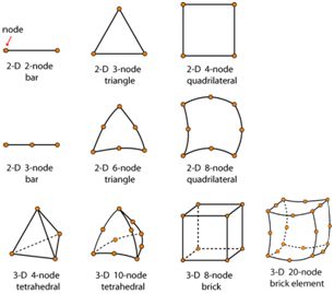
1D modelling tactics are used for modelling line-kind contributors which includes columns / piers, beams or piles. Representation of the road is self-described with the aid of using the consumer through a phase and all geometric homes of the member (width, height, etc.).
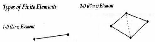
2D modelling strategies are normally used for plate-kind contributors which includes walls, slabs, shells, bridge abutments, tanks, silos or domes. For these kind of contributors, the 2 dimensions perpendicular to the thickness are taken into consideration as plenty large as the thickness. It is consequently best the slab thickness that ought to be described as phase belongings with the aid of using the consumer previous to the evaluation.
However, there exist obstacles while the use of 2D modeling strategies as strict regulations are to be adhered to, a good way to achieve the maximum correct results. The essential regulations that follows are the ratio among the thickness and location of the plate itself, as using a completely excessive thickness to location ratio plate will input the world of 3-D modelling wherein all assumptions made the use of 2D factors now not holds true.
3-D factors may be used for modelling any structural member.
In this case, every member of the version is normally divided into same volumetric 3-D factors. As it stands, CAD programs (which includes SolidWorks) are used to create those 3-D fashions, it presents the possibility to create greater complicated 3-D fashions used for structural evaluation.
For instance, the identical motor motorcycle body visible with the 1D factors may be replicated the use of 3-D factors, with the subsequent result: A large downside of the use of 3-D factors, is its modelling (the above version should soak up to 10x longer than 1D modelling) and fixing time. 3-D factors tries to absolutely seize the physics of the version, internally and externally with the aid of using making use of computation-heavy calculations required to remedy the evaluation on the price of greater time spent at the version itself.
Q15) Define nodal Unknowns and field variables.
A15)
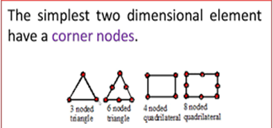
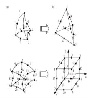
When a domain (a geometrical region) is meshed, its miles decomposed into a chain of discrete (as a quit end result finite) elements. The meshed geometry of an exhaust manifold is examined with inside the decide below. It may be visible that the factors with inside the mesh conform thoroughly to the geometry, and constitute consequently an outstanding approximation of the geometry. The manifold on this case is meshed with a 3-dimensionalimensional brick detail which includes 20 nodes. Adjacent factors are related to every unique AT the nodes.
A node is virtually a aspect in region, described via its coordinates, at which degrees of freedom are described. In finite detail evaluation a diploma of freedom can take many forms, however is primarily based totally upon at the shape of evaluation being performed. For example, in a structural evaluation the ranges of freedom are displacements (Ux, Uy and Uz), whilst in a thermal evaluation the diploma of freedom is temperature (T). In the exhaust manifold example, there are four ranges of freedom at every node – Ux, Uy, Uz and T, because of the reality the evaluation is a coupled temperature-displacement evaluation (because of thermal enlargement effects). These field variables are calculated at each node from the governing equation.
This is feasible thinking about the reality that the ones elements permit the solution the various nodes to vary in non-linear ways (see segment on shape functions), this is a critical feature whilst subject variables extrude rapidly.
Q16) What is coordinate systems, Shape Functions – linear, quadratic and cubic?
A16)
The coordinate gadget is orientation in phrases of x, y and z relative to the automobile, as wherein axis is going wherein path; usually described as in phrases of the instructions of the automobile.
For instance ISO uses as proven above, while SAE uses and there are masses extra versions than the ones two. In the VeSyMA automobile templates, there's the vehicle XYZ block with inside the pinnacle left hand nook of the diagram layer that defines the coordinate gadget. As proven below, this lets in customers to outline the orientation of the automobile.
And you’ll probably want to a minimum of circulate one subsystem to paintings in another. For instance, it's far not unusual place that the engine is designed from a neighborhood starting place and alongside the x axis.
This way that the starting place and coordinate gadget desires to be translated and likely turned around to get the sub-structures into the precise location.
In VeSyMA this could be achieved the usage of the Coordinates Blocks and connectors which might be mentioned on this weblog submit approximately multimode orientation. Position of Sensors and Measurement It is continually really well worth thinking about sensors, dimension and the way the orientation and role of the sensors can substantially have an effect on your effects.
If you vicinity the sensors of a automobile on the starting place, then that can produce sudden effects whilst searching at what they measure. Consider having a severe starting place 2 vehicle lengths at the back of the rear axle; whilst turning to the left the sensor could begin shifting to the right.
This could purpose the measured lateral acceleration now no longer to symbolize the predicted lateral acceleration of the automobile. When searching on the facts with inside the control Bus then you’ll see that maximum of the variables are defined with the aid of using the path in place of the axis. For instance, chassis bus. Longitudinal Velocity in place of vex as this eliminates confusion with regard to axis, and signal convention.
Earth-Fixed (Inertial) Coordinate System
The earth-fixed coordinate system (XE, YE, ZE) axes are fixed in an inertial reference frame. The inertial reference frame has zero linear and angular acceleration and zero angular velocity. In Newtonian physics, the earth is an inertial reference.
Q17) What is shape functions for Linear, Quadratic, cubic, bar and triangular elements?
A17)
In the finite detail method, non-stop fashions are approximated the use of records at a finite wide variety of discrete locations. Dividing the shape into discrete factors is known as discretization.
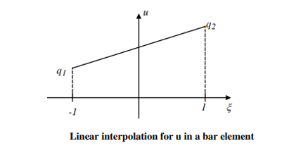
Let us isolate a bar detail from the non-stop bar. The deformations on the ends of the elements (called “nodes”) are a part of the unknown’s with inside the finite detail evaluation problem. Let us now outline form features for the bar detail so one can linearly interpolate deformation inside the detail. We will outline the form features in any such manner that they may be used for a detail of any size. That is, we can normalize the duration of the detail with the aid of using the usage of a brand new neighborhood coordinate gadget proven below.
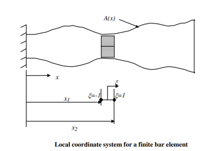
The ξ- coordinate system is defined in such a way that ξ = - 1 to 1 would cover the entire element irrespective of what x1 and x2 are for a given element. The following relationship gives that range for ξ as x varies from x1 to x2.
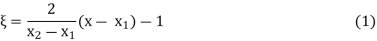
Now we define two shape functions in the ξ-coordinate system shown below.

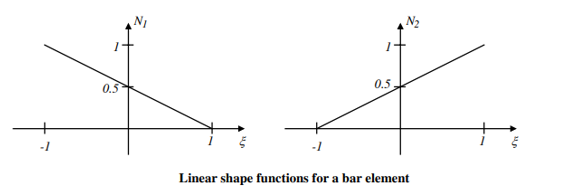
Using these shape functions, the deformations within the element are interpolated as follows:
u = N1q1 + N2q2 (3)
Where q1 and q2 are the deformations at the ends (nodes) of the element. It is easy to see that it varies linearly as shown in Figure 3.
Equation (3) can be written in matrix notation as
u = {N1 N2} = Nq (4)


