Unit - 4
Steam nozzles & Steam Turbines
Q1) State different types of steam nozzles.
Ans. Types of steam nozzles
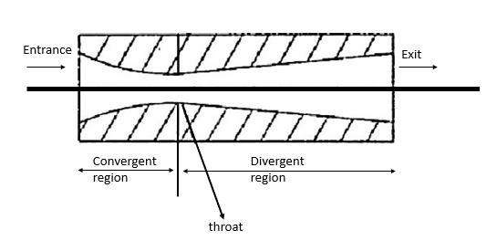
Convergent nozzle
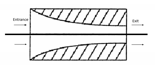
Divergent nozzle
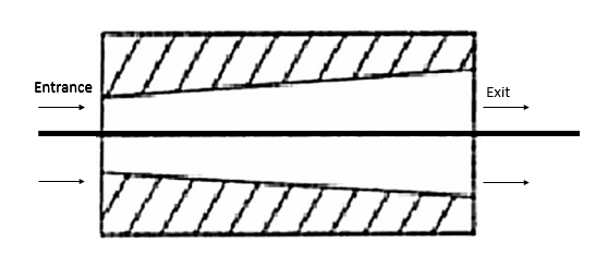
Convergent- divergent nozzle
Q2) State various application of steam nozzles.
Ans. Applications of steam nozzle
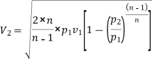
Q3) Derive an expression for velocity of steam through nozzle.
Ans. Consider a mass flow of steam through a nozzle.
Let  =Velocity of steam at the entrance of nozzle in m/s
 =Velocity of steam at any section considered in m/s
 =Enthalpy or heat of steam entering the nozzle in kJ/Kg and
 =Enthalpy or total heat of steam at the section considered in kJ/kg.
We know that for a steady flow process in a nozzle.
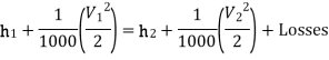
Neglecting losses in a nozzle.
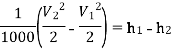
 ………. (1)
 =Enthalpy or heat drop during expansion of steam in a nozzle
=
Since the entrance velocity or velocity of approach is negligible as compared to  Therefore from the equation (1)
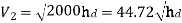 ---2
---2
In actual practice there is always a certain amount of friction present between the steam and nozzle surfaces. This reduces the heat drop by 10 to 15 percent and thus the exit velocity of steam is also reduced correspondingly. Thus the above relation may be written as :
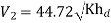
Where K is nozzle coefficient or nozzle efficiency.
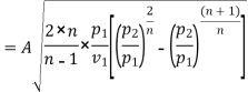
Q4) Derive an expression for mass flow rate through nozzle.
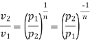
Ans. The flow of steam, through the nozzle is isentropic which is approximately represented by the general law:
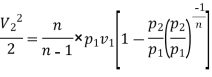
We know that gain in kinetic energy
=  ….. Neglecting initial velocity of steam
And Heat drop = Work done during Rankine cycle
=
Since gain in kinetic energy is equal to heat drop therefore
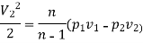
=  ………… (1)
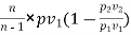
We know that 

 ………… (2)
Substituting the value of  in equation 1
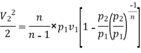
= 
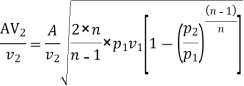
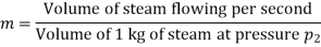
Now the volume of steam flowing per second
= Cross sectional area of nozzle x Velocity of steam =
And volume of 1kg of steam i.e. specific volume of steam at pressure 
=
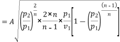
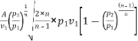
Mass of steam discharged through nozzle per second

Substituting the value of  from equation 2
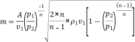
=

Q5) Classify steam turbines.
Ans. The flow of steam, through the nozzle is isentropic which is approximately represented by the general law:

We know that gain in kinetic energy
=  ….. Neglecting initial velocity of steam
And Heat drop = Work done during Rankine cycle
=
Since gain in kinetic energy is equal to heat drop therefore

=  ………… (1)
We know that 
 ………… (2)
Substituting the value of  in equation 1
= 

Now the volume of steam flowing per second
= Cross sectional area of nozzle x Velocity of steam =
And volume of 1kg of steam i.e. specific volume of steam at pressure 
=
Mass of steam discharged through nozzle per second

Substituting the value of  from equation 2

=

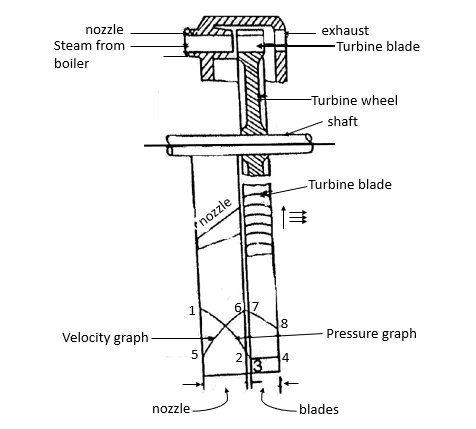
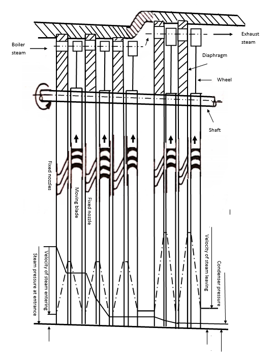
Q6) Explain construction & working of impulse steam turbine.
Ans. Impulse turbine
De-level impulse turbine
2. Runner and blades:
3. Casing:
Pressure and velocity of steam in an impulse turbine
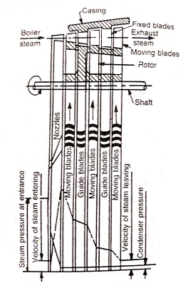
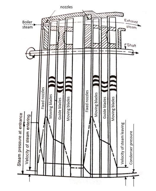
Q7) Explain construction & working of reaction steam turbine.
Ans. Reaction turbine
Parson's reaction turbine
Parsons turbine is the simplest type of reaction steam turbine and is commonly used. It has the following main components:
2. Guide mechanism:
3. Turbine runner:
4. Draft tube:
Pressure and velocity of steam in reaction turbine
Q8) What is compounding of steam turbine? State its necessity.
Ans.
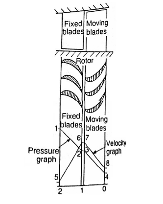
Q9) Explain different types of compounding.
Ans. The following three methods are commonly employed for reducing the rotor speed:
2. Pressure compounding of an impulse turbine
3. Pressure velocity compounding of an impulse turbine
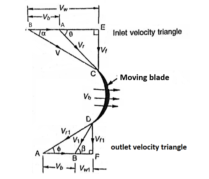
Q10) Draw & explain velocity diagrams of impulse steam turbine.
Ans. Velocity triangles for moving blade of an impulse turbine
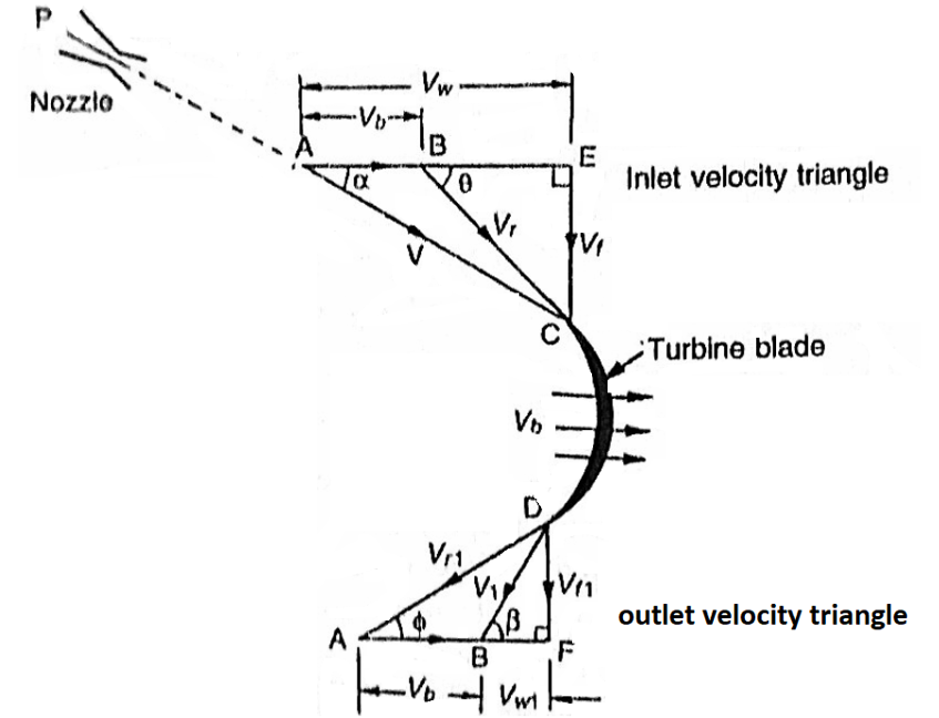
Let
 Linear velocity of the moving blade (AB)
V=absolute velocity of steam entering the moving blade (AC)
 =relative velocity of Jet to the moving blade (BC). It is the vectorial difference between
  and V.
 velocity of flow at entrance of the moving blade.
 velocity of whirl at entrance of the the moving blade
 =angle which the relative velocity of Jet to the moving blade makes with the direction of motion of the blade
 =Angle with the direction of motion of the blade at which the jet enters the blade.
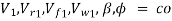 rresponding values at exit of the moving blade


Impulse turbines


Combined velocity triangle for moving blades


Q11) Draw & explain velocity diagrams of reaction steam turbine.
Ans. Velocity triangles for moving blades of reaction turbine
 linear velocity of the moving blade (AB)
V=absolute velocity of steam entering the moving blade (BC)
 =Relative velocity of jet to the moving blade (AC).
 =Velocity of flow at entrance (EC). It is the vertical component of V.
 Velocity of whirl at entrance (BE). It is a horizontal component of V.
 =angle with the direction of motion of the blade at which the steam enters the blade
 =angle which the relative velocity of jet makes with the direction of motion of the blade
 rresponding values at exit of the moving blade

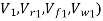


Combined velocity triangle for moving blades
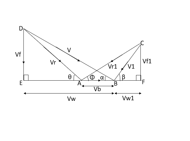


Q12) What do you mean by governing of steam turbine? Explain various types of governing of steam turbine.
Ans. Steam turbine governing and control
- Throttle governing
- Nozzle governing
- Bypass governing
- Combination of 1 and 2 and 1 and 3.
- Throttle governing
(a) (b)
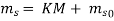
Where  Steam consumption in kg/h at any load M
 Steam consumption in kg/h at no load
 Steam consumption in kg/h at full load
M= Any other load in kW
 Full load in kW and
K= Constant
 varies from about 0.1 to 0.14 times the full load consumption. The equation can be written as
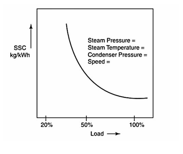
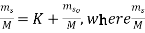 is called the steam consumption per kWh
2. Nozzle governing
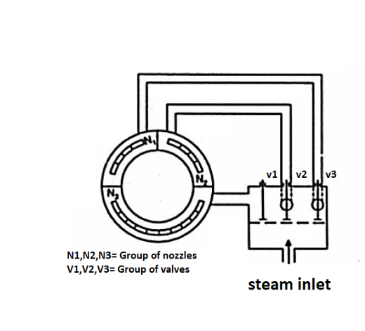
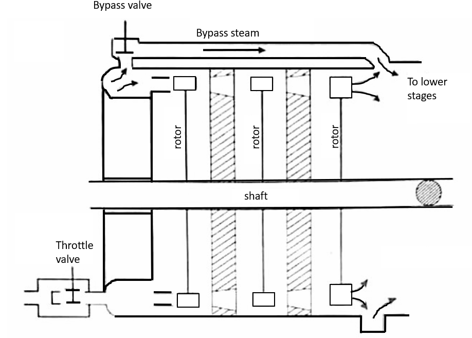
3. Bypass governing
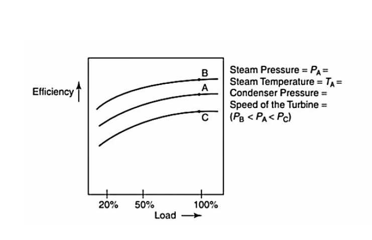
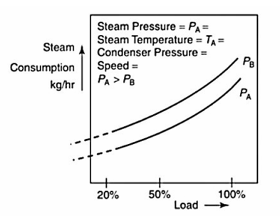
Q13) Explain performance characteristics of steam turbine.
Ans.
(a)


(b)


(C)
(D)
Q14) State different losses in steam turbine.
Ans.
Internal losses in turbines
Strictly speaking an ideal turbine (having 100 percent gross efficiency) will do the work equivalent to the isentropic enthalpy or heat drop of the steam used in the turbine. But in actual practice, the work done by a turbine is much less than isentropic heat drop of the steam used. There are several factors which effect the performance of a steam turbine. All these factors which reduce the output of the turbine are known as internal losses. Do there are many internal losses in a steam turbine, yet the following are important from the subject point of view:
Energy losses in steam turbines
The increase in heat energy required for doing mechanical work in actual practice as compared to the theoretical value, in which the process of expansion takes place strictly according to the adiabatic process, is termed as energy loss in steam turbine.
The losses which appear in an actual turbine may be divided into two following groups
1. Internal losses: Losses directly connected with steam conditions while in its flow through the turbine. They may be further classified as
(ii) Losses in regulating valves
(iii) Losses in nozzles (guide blades)
(iv) Losses in moving blades:
(a) Losses due to trailing edge wake
(b) Impingement losses
(c) Losses due to leakage of steam through the angular space
(d) Frictional losses
(e) Losses due to turning of steam jet in the blades
(f) Losses due to shrouding
(v) Leaving velocity losses (exit velocity)
(vi) Losses due to friction of disc carrying the blades and windage losses
(vii) Losses due to clearance between the rotor and guide blade discs
(viii) Losses due to wetness of steam
(ix) Losses in exhaust piping etc.
- Mechanical losses
- Losses due to leakage of steam from the Labyrinth gland scale.
Q15) Explain selection of steam turbine.
Ans.
Q16) Explain reheat factor with neat sketch.
Ans.
Let  = initial pressure of the steam.
 =pressure of steam leaving the first stage
 =pressure of steam leaving the second stage.
 =final pressure of the steam
 =initial temperature of the steam
 =Stage efficiency for each stage of the turbine.
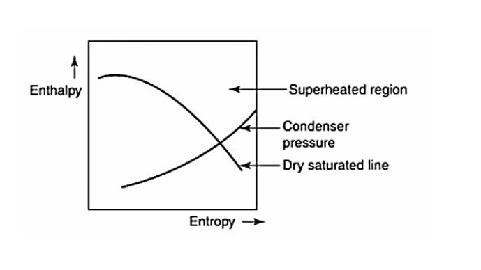
Now let us draw the expansion of steam in three stages on a Mollier chart as shown in figure
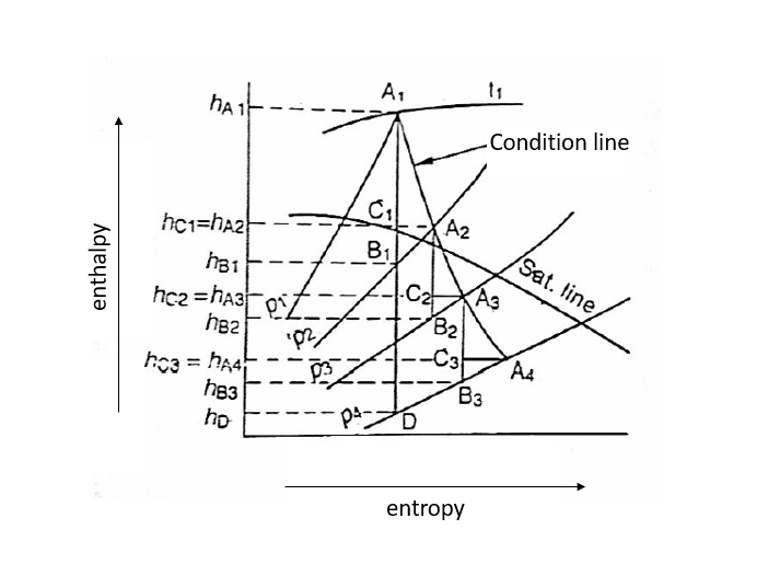


It will be interesting to know from the Mollier diagram that the pressure lines diverge from left to right, which shift the isentropic expansion lines at each stage slightly towards the right side in the diagram. Or in other words enthalpy or heat drop is slightly increased. The sum of increased heat drops is known as cumulative heat drop.
Now the ratio of cumulative heat drop to the isentropic heat drop is known as reheat factor
Mathematically, reheat factor 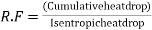
=
=
Q17) Compare between impulse turbine and reaction turbine
Ans.
S.no. | Impulse Turbine | Reaction Turbine |
1. | The steam flows through the nose and impinges on the moving blades | The steam flows first through guide mechanism and then through the moving blades. |
2. | The steam impinges on the buckets with kinetic energy. | The steam glides over the moving vanes with pressure and kinetic energy. |
3. | The steam may or may not be admitted over the whole circumference. | The steam must be admitted over the whole circumference. |
4. | The steam pressure remains constant during its flow through the moving blades. | The steam pressure is reduced during its flow through the moving blades. |
5. | The relative velocity of steam while gliding over the blades remain constant. | The relative velocity of steam while gliding over the moving blades increases. |
6. | The blades are symmetrical | The blades are not symmetrical. |
7. | The number of stages required are less for the same power developed. | The number of stages required are more for the same power developed. |
Q18) Compare between throttle and nozzle control governing.
Ans.
Sr.No | Aspects | Throttle Control | Nozzle control |
1. | Throttling losses | Severe | No throttling losses (Actually there are a little throttling losses in nozzles valves which are partially open) |
2. | Partial admission losses | Low | High |
3. | Heat drop available | Lesser | Larger |
4. | Use | Used in impulse and reaction turbine both | Used in impulse and also in reaction (if initial stage impulse turbines) |
5. | Suitability | Small turbines | Medium and larger turbines |


