Unit – 2
Impulse Water Turbines
Q1) Explain working of hydro electric power plant with neat sketch.
Ans.
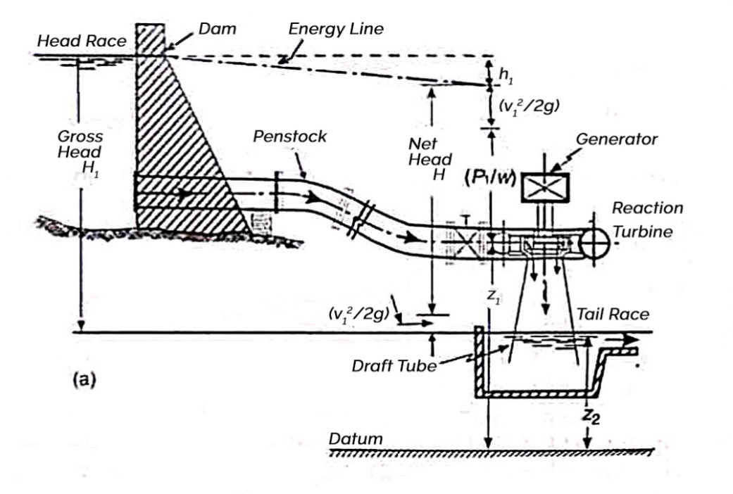
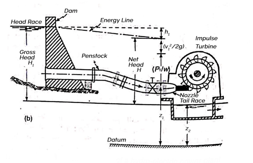
A dam
Penstock
Turbine
Tail race
Q2) Classify hydraulic turbines.
Ans. Classification of hydraulic turbines
- impulse turbine
- reaction turbine
- Tangential flow turbine
- Radial flow turbine
- Axial flow turbine
- Mixed flow turbine
- High head turbine
- Medium head turbine
- Low head turbine
- Low specific speed turbine
- Medium specific speed turbine
- High specific speed of turbine
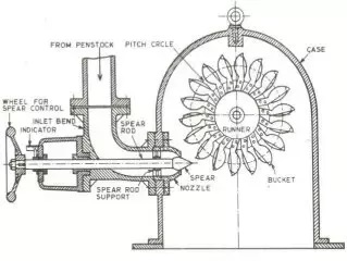
Q3) Explain working of Pelton wheel turbine with neat sketch.
Ans.
Q4) Explain principle of working of impulse turbine.
Ans.
Q5) Explain design aspect of Pelton wheel turbine.
Ans.
The ideal velocity of jet usually known as spoutting velocity
Actual velocity of the jet is slightly less due to friction loss in the nozzle
Thus V = 
Where, Cv=coefficient of velocity
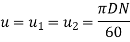
Velocity of wheel u= 
Where Ku = speed ratio
= 0.43 to 0.47
Angle through which jet of water gets deflected in buckets =1650
Least diameter d of the jet
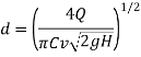
Where Q = discharge through jet in 
Mean diameter D of Pelton wheel may be obtained as follows
D= 
Jet ratio m= 
For maximum efficiency jet ratio should be from 11 to 14
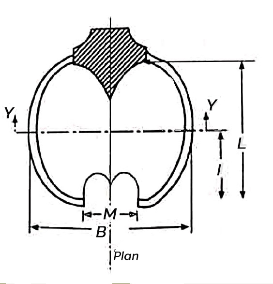
Some of the main dimensions of the bucket of Pelton wheels as shown
B= (4 to 5) d
C= (0.81 to 1.05) d
M=(1.1 to 1.25) d
Angle  = 5° to 8°
L= (2.4 to 3.2) d
l= (1.2 to 1.9) d
 = 10° to 20°
 50 to 80
Number of buckets = Z= 
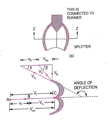
Q6) Draw & explain velocity diagrams of Pelton wheel turbine& derive expression for hydraulic efficiency.
Ans.
H= Net head acting on the Pelton wheel
= 
 Gross head

 Dia of penstock
N= Speed of the wheel in r.p.m
D= diameter of the wheel
d=diameter of the jet
Then,  Velocity of jet at inlet
The velocity triangle at inlet will be a straight line where
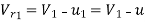

 =0 and
  =0
=0
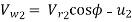
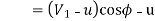
From the velocity triangular at outlet, we have

The force exerted by the of water in the direction of motion is given by equation
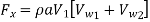
As the angle  is an acute angle, positive sign should be taken
a=area of jet 
Work done by the jet on the runner per second
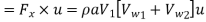
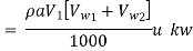
Power given to the runner by the jet
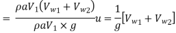
Work done per second per unit weight of water striking
The energy supplied to the jet at inlet is in the form of kinetic energy and is equal to 
Kinetic energy of jet per second 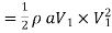
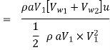
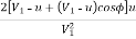
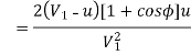
Hydraulic efficiency
=
 u
u
Now 
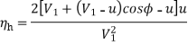
=
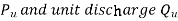
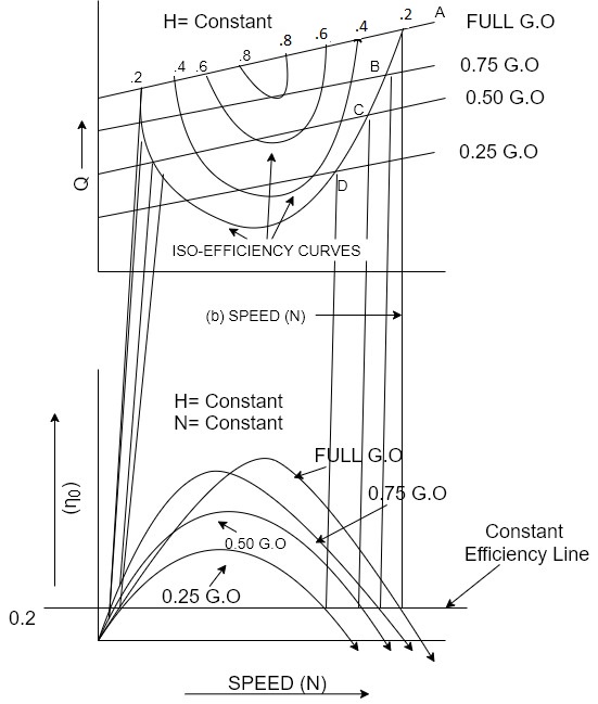
Q7) Explain performance characteristics of Pelton wheel turbine.
Ans.
Constant head curves
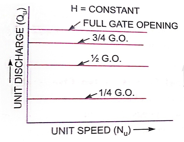
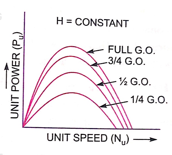
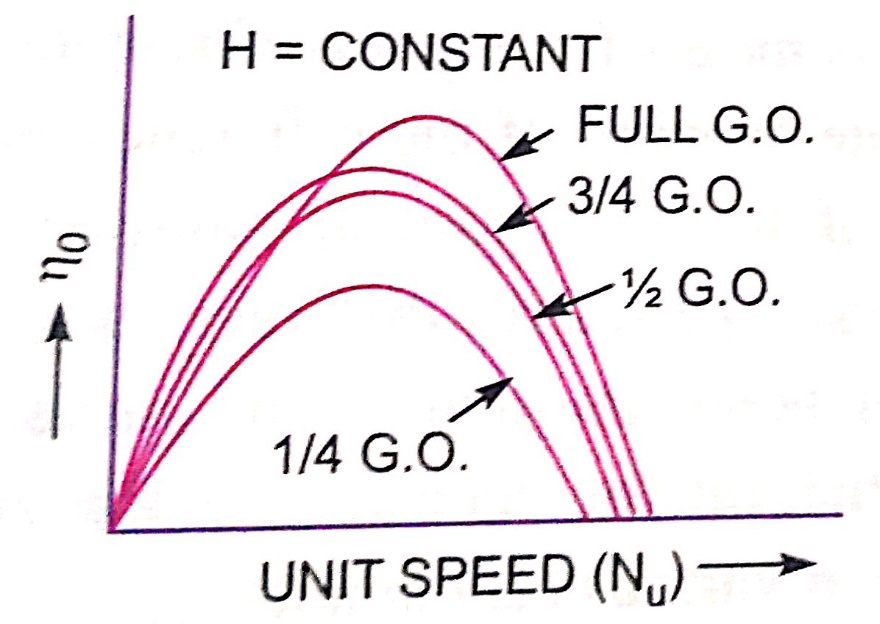
For a Pelton wheel
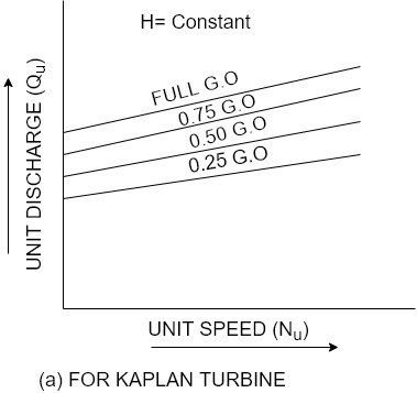
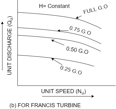
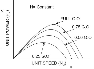
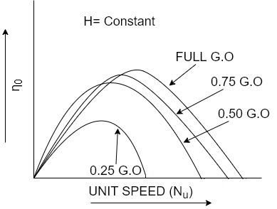
For reaction turbines


Operating characteristic curves for constant speed curves
Constant efficiency curves or Muschel curves or iso-efficiency curves


Q8) Define Specific speed & state its significance.
Ans.
It is denoted by symbol 
Significance:-
Q9) Derive expression for specific speed.
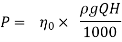
Ans. Overall efficiency  =
=
 =
= 
Where H=head under which the turbine is working
Q=discharge through turbines
P=power developed for shaft power
P Q× H
Q× H
As  and
and  are constant …..(ii)
D= diameter of actual turbine
N=speed of actual turbine
u=tangential velocity of the turbine
 Specific speed of turbine
V=absolute velocity of water
But. u  V where V
 √H
√H
u √H (iii)
But. u=
u DN….(iv)
From equation (iii) and (iv)
√H.  DN
DN
Or D
Discharge Q= A×V
A  B×D
B×D

V √H
√H

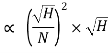


Put the value of Q in equation (ii)
 ×H
×H

P=
where K=constant of proportionality
If P=1 and H=1 Speed N=Specific speed
Put these values in above equation


Or 

Q10) Explain multi jet Pelton wheel turbine.
Ans.
Q11) Write a short note on selection of turbines.
Ans. Following factors are considered for selecting a particular turbine at place
1) Head:- The net head under which the turbine is working plays an important role for selecting turbine.
The type of turbine for different heads
Net head in m | Types of turbine |
300m or more | Pelton turbine |
150m to 300m | Pelton or Francis |
50m to 150m | Francis turbine |
Less than 50 m | Kaplan or propeller |
2) Specific speed :- The specific speed is also an important factor for deciding the type of turbine to be installed at a place.
Specific speeds | Types of turbines |
85 to 30 | Pelton wheel with single jet |
31 to 50 | Pelton wheel with double jet |
51 to 225 | Francis |
256 to 860 | Kaplan or propeller |
3) Part load operation :-
4) overall cost of installation and cavitation characteristics :-


