Unit 6
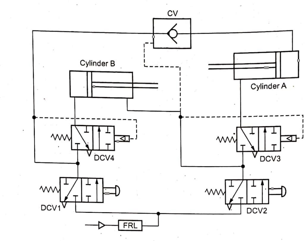
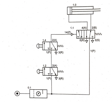
Q.1 Sequential operations of two pneumatic cylinders are required as follows:
a) Cylinder A extends
b) Cylinder B extends
c) Cylinder B retracts
d) Cylinder A retracts
Develop a pneumatic circuit using a pilot operated 4/2 DCV and a roller operated valves. (Do not use sequence valve)
Sol:
Q.2 A pump supplies oil at 0.0016 m3/s to a 40 mm diameter double-acting hydraulic cylinder. If the load is 5000 N (extending and retracting) and the rod diameter is 20 mm, find the (a) Hydraulic pressure during the extending stroke. (b) Piston velocity during the extending stroke. (c) Cylinder kW power during the extending stroke. (d) Hydraulic pressure during the retracting stroke, (e) Piston velocity during the retracting stroke. (f ) Cylinder kW power during the retracting stroke.
Solution:
We have 
a) Hydraulic pressure during the extending stroke is

b) Piston velocity during the extending stroke is

c) Cylinder velocity during the extending stroke is

d) Hydraulic pressure the retracting stroke is

e) Piston velocity during the retracting stroke is

f) Cylinder kW power during the retracting stroke is

Q.3 A cylinder with a bore of 150 mm and a piston rod diameter of 105 mm, has to extend with a speed of 7 m/s, pressure applied is 150 bar. Calculate
(a) The flow rate in LPM of oil to extend the cylinder
(b) The flow rate in LPM from annulus side to extend the cylinder.
(c) The retract speed in m/min using (a).
(d) The flow rate from full bore end on retract.
Solution:
Area of piston is given by

Area of rod is

Hence, 
Given,  and
and  .
.
a) Flow rate of oil to extend in LPM:


b) Flow rate of oil to extend from annulus in LPM:


c) Retract speed in m/min using (a):


d) Flow rate from full bore end on retract:


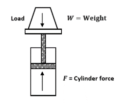
Q.4 A 6000 N weight is to be lifted upward in a vertical direction for the system shown in Fig. 1.17. Find the cylinder force required to (a) Move the weight at a constant velocity of 1.75 m/s. (b) Accelerate the weight from zero velocity to 1.75 m/s in 0.5 s.
Solution;
a) For a constant velocity, the cylinder force to move weight at a constant velocity of 1.75m/s

b) Force required to accelerate the weight:
First we shall calculate acceleration

Force required to accelerate the weight is

The cylinder force  required is equal to the sum of the weight and acceleration force

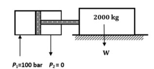
Q.5 A mass of 2000 kg is to be accelerated horizontally up to a velocity of 1 m/s from the rest over a distance of 50 mm (Fig. 1.20). The coefficient of friction between the load and guide is 0.15. Calculate the bore of the cylinder required to accelerate this load if the maximum allowable pressure at the full bore end is 100 bar (take seal friction to be equivalent to a pressure drop of 5 bar). Assume that the back pressure at the annulus end of the cylinder is zero.
Solution:
In this case,  and a is unknown. Using the equation
  .
.
We have,


The force to acceleration the load is given by

The force p to overcome the load friction is given by

The total force to acceleration the load and overcome friction is
The cylinder area required for a given thrust is calculated form

The pressure available pressure at the full bore end of the cylinder minus the equivalent seal-break out pressure
Pressure available
Area is given by
Area
Now area is also given by
Area
Where D is the diameter. Comparing the two equations, we get . The cylinder diameter is thus 55.4mm. This neglects the effect of any back pressure. The nearest standard cylinder above has a 63mm diameter bore.
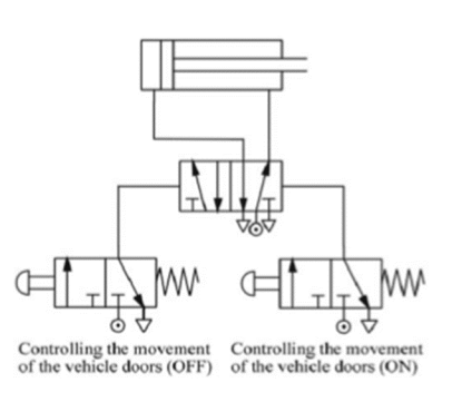
Q.6 Pneumatic system is to be designed to operate a door of public transport vehicles. Assuming that the opening and closing of the doors are controlled by two button switches ON and OFF. When the button switch ON is pressed, the door will open. When the button switch OFF is pushed, the doors will close.
Sol:
Q.7 Label the component and analyze the circuit
Sol:
Step I: Sketch the circuit and label it
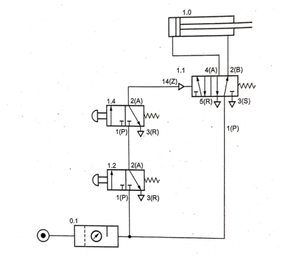
Step II: List of components
S.No | Component | Notation used | Specification/Function |
1. | FRL | 0Z | To filter, regulate and lubricate flow. |
2. | DCV | 0S | Directional control valve – 3/2 mechanical actuated. |
3. | DCV | 1S | Directional control valve – 5/2 push button operated spring return. |
4. | Actuator | 1A | Double acting pneumatic cylinder. |
Step III: Operation
Q.8 Analyze the following circuit

Sol:
Step I: Sketch the circuit
Step II: Labelling
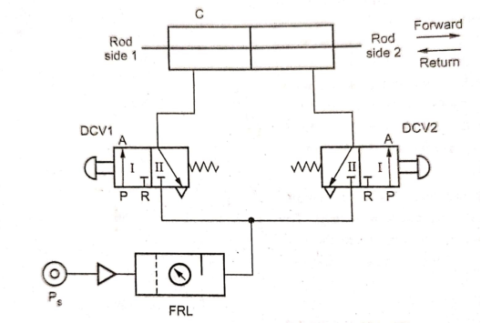
Step III: List of components
S.No | Component | Notation used | Function/Specification |
1. | Power source |
| Includes motor, compressor etc. to compress the atmosphere air. |
2. | Filter, regulator and lubricate unit | FRL | Do conditioning of compressed air. |
3. | Directional control valve | DCV1, DCV2 | DCV1 and DCV2: 3/2, push button operated, spring return valve |
4. | Consumer/Cylinder | C | Pneumatic cylinder with piston rod on the both sides. |

Step IV: Sequence of operation
Q.9 Draw a simple hydraulic circuit which will operate a hydraulic cylinder of a machine. The load during forward stroke is 15 KN and that during return is approximately 9.5 KN. Forward and return speeds are approximately 3.5m/min and 5.5 m/min resp. Total stroke of circuit is 300 mm. Provision is required to hold the cylinder anywhere in between the end positions. Select the different components from the data given. Specify rating of components in case not available in given data.
Sol:
Step I: Circuit diagram
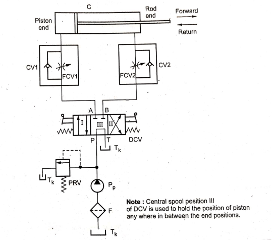
Double acting cylinder is required to be used for the given application. Also provision is required to hold the cylinder anywhere in between the end positions. This can be achieved from the above circuit.
Step II: Design stage
Given,


A) Calculations for forward stroke:
The cylinder piston acts against the load of 15kN through a distance 300mm. the speed during this stroke is given 3.5m/min.

Selection: Selecting model ‘A4’ of cylinder for getting reliable safety.
 From the Table 16.10
Bore diameter/piston diameter
Rod diameter
Now, calculating pressure and flow rate for forward stroke,


 Effective pressure area is piston area


Flow rate during this stroke,


B) Calculation for return stroke:
The speed during the return stroke is given 5.5m/min and the load is approximately 9.5kN.

Note for return stroke pressure is applied on annular area which is  .
.
Calculating pressure and flow rate for return stroke,


Flow rate during return stroke,


Put the maximum working pressure and maximum flow rate (discharge ) as system parameters.
System parameters:
A) Maximum working pressure:
 (during forward stroke)
b) Maximum flow rate
 (during return stroke)
1) Oil reservoir: Model: T2:
By thumb rule, reservoir capacity should be 2 to 3 times the maximum flow rate.


Hence, T2 model is selected. Refer Table 16.2.
2) Suction Strainer: Model : S1:
For maximum flow rate of 15.61 lpm, model S1 is suitable, hence selected.
3) Hydraulic pump: Model: P3:
From the Table 16.4(b), selecting model “P3”, for the flow rate of 16.1 at pressure of 35 bar.
Note: Pump minimum lpm=2 Maximum flow rate
= 2 15.61=31.22 lpm
You can select other model of pump using this.
4) Directional Control Valve (DCV): Model : D1:
The DCV is selected form the Table 16.7 on the basis of working pressure (33.95 bar) and maximum flow rate (15.61 lpm) is model D1.
5) Pressure Relief Valve (PRV): Model: R2:
The satisfying model for pressure relief valve is R2, which is selected from Table 16.5
6) Flow control valve: Model: F3:
The flow control valve satisfying system conditions is elected from Table 16.6. The model selected is F3.
7) Check Valve (CV): Model: C2:
The check valve model selected is C2, which is selected from Table 16.8
8) Cylinder: Model: A4:
The cylinder model ‘A4’ is already selected, considering safety aspect.
Component | Model selected | Model capacity |
Oil reservoir | T2 | 100 lit. |
Suction strainer | S1 | 38 lpm |
Hydraulic pump | P3 | 16.1 lpm, 70 bar |
Directional control valve | D1 | 19 lpm, 350 bar |
Pressure relief valve | R2 | 19 lpm, 210 bar |
Flow control valve | F3 | 0-16.3 lpm, 105 bar |
Check valve | C2 | 30.4 lpm, 210 bar |
Cylinder | A4 |
|


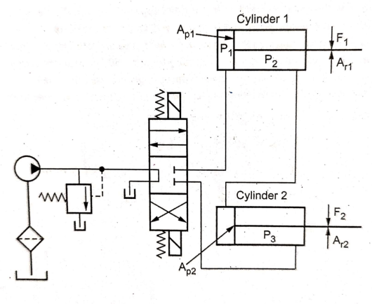
Q.10 Two double acting hydraulic cylinders are synchronized by connecting them in series. The load acting on each cylinder is 4000 N. Cylinder 1 has the piston diameter 50 mm and rod diameter 20 mm. If the cylinder extends 200 mm in 0.05 sec, find the following
a) The pressure requirement of the pump
b) Flow Capacity of the pump
c) Pump Output
d) Capacity of motor during pump if overall efficiency of pump is 80%
Sol:


To find: P= Pressure supplied by pump=?


Capacity – motor =?
We have, for synchronized operation,


 Pressure requirement of pump


Now, extension velocity,


Now, flow capacity of pump:


Now,
Pump output

Capacity of motor driving pump


