Unit 2
Q.1 Explain Magnification Factor
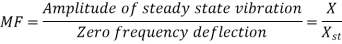
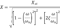
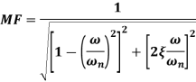
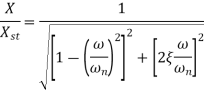
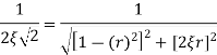
A1) Magnification factor is defined as the ratio of amplitude of steady state vibrations ‘X’ to the zero-frequency deflection ‘Xst’
Where,

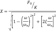
The amplitude X of the steady state forced harmonic vibration is given as

Q.2 Explain frequency response to harmonic excitation
A2) Figure below shows the magnification factor – frequency ratio plot and phase angle – frequency ratio plot.
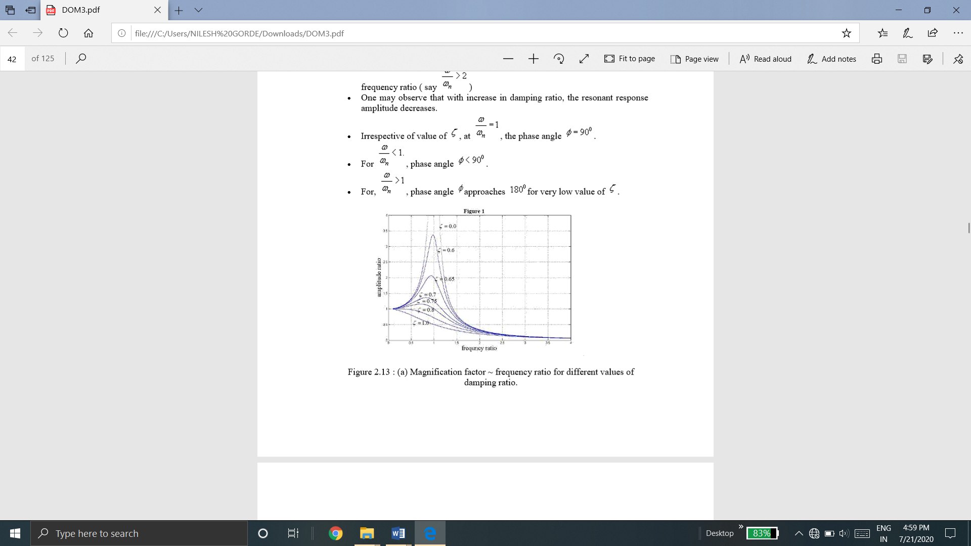
(a) magnification factor – frequency ratio plot
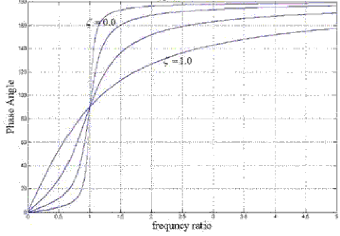
(b) phase angle – frequency ratio plot
Following observation can be made from these plots.


Q.3 What is force and motion transmissibility
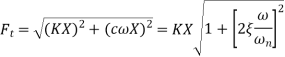
A3) Force Transmissibility
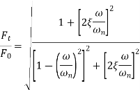
Force Transmissibility is defined as the ratio of the force transmitted to the supporting structure of foundation Ft to that of force imposed upon the system F0. Force transmissibility measures the effectiveness of the vibration isolating material.

Motion Transmissibility
Motion Transmissibility is defined as the ratio of absolute amplitude X of the mass to the amplitude of the base excitation Y.

In many industrial applications, one may find the vibrating machine transmit forces to ground which in turn vibrate the neighboring machines. So, in that contest it is necessary to calculate how much force is transmitted to ground from the machine or from the ground to the machine.
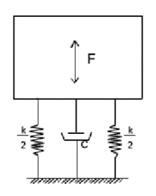
Vibrating system
Figure. shows a system subjected to a force  and vibrating with
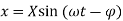
This force will be transmitted to the ground only by the spring and damper.
Force transmitted to the ground
It is known that for a disturbing force  , the amplitude of resulting oscillation

Substituting these equations and defining the transmissibility TR as the ratio of the force transmitted Force to the disturbing force one obtains
Comparing equations for support motion, it can be noted that

i.e. Mathematically, Force Transmissibility = Motion Transmissibility
When damping is negligible,
Q.4 Explain Quality factor and bandwidth. Derive expression for bandwidth.
A4) Quality factor
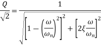
The magnification factor or amplitude ratio of a system at resonance is called as Quality Factor or Q factor of the system
At resonance means,
At, 

Bandwidth
Fig below shows a response curve of amplitude ratio  versus frequency ratio
  for values of
  less than 0.1
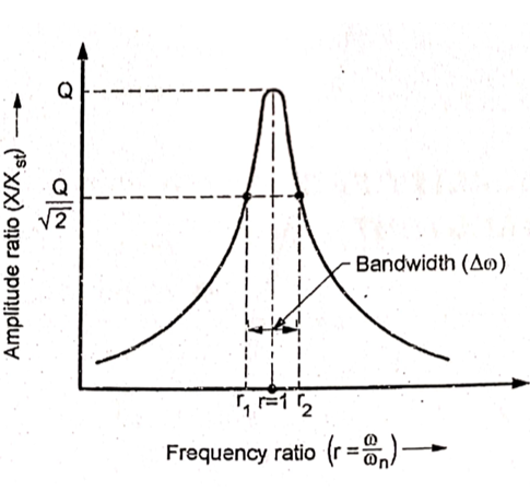
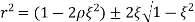
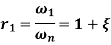
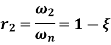
Let r1 and r2 be the frequency ratio where, the amplitude ratio falls to  and are called as half power points.
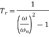
The difference between the frequencies associated with the half power points is called as bandwidth of the system.
We have,
Substituting,

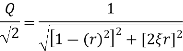
Now,

Squaring both sides and solving, we get
For small values of  and
and  ,
,

 higher power terms of
Neglecting higher power terms
Bandwidth 

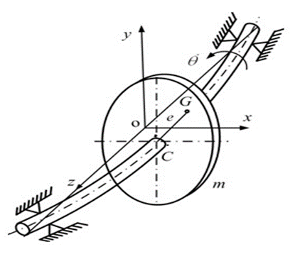
Q.5 Write a note on critical speed of shaft.
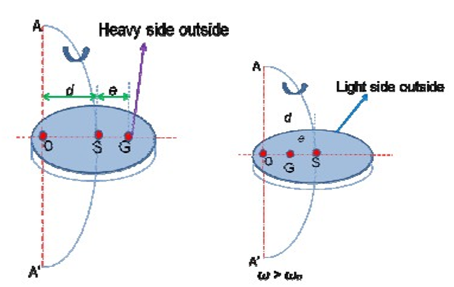
A5) When rotor is mounted on a shaft its center of gravity usually not coincide with the rotation of the shaft. This C.G. is displaced from axis of rotation although amount of displacement may very slow.
As a result, shaft is subjected to a centrifugal force when it begins rotate. The CF acting radially outward, which make the shaft to bend in the direction of eccentricity of the C.G. This unbalance CF, a shaft start vibrating violently in the direction perpendicular to the axis of the shaft. This phenomenon is known as whirling of shaft.
The speed at which the shaft starts to vibrate violently in the direction perpendicular to the axis of the shaft is known as critical speed.
Consider a vertical shaft having negligible inertia and carrying a single rotor is shown in fig
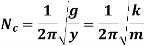
Where,
 = Critical speed of shaft in r.p.s
 = Static deflection of shaft
Ranges of speed

When the speed of shaft is less than the critical speed, then the deflection of shaft is positive.
Deflection of shaft increases with shaft speed. Fig (a)
2. 
When the speed of shaft is equal to the critical speed, then the deflection of shaft is tends to infinity. This may lead to failure of shaft
3. 
When the speed of shaft is greater than the critical speed, then the deflection of shaft is negative. Fig (b)

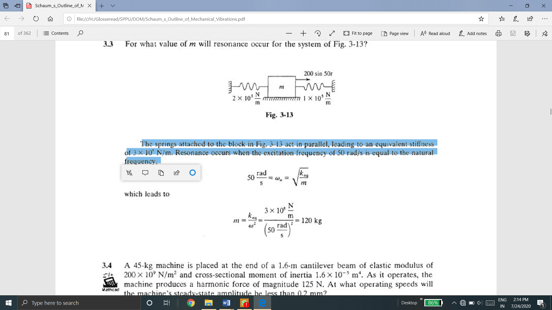
Q.6 For what value of m will resonance occur for the system of Fig.
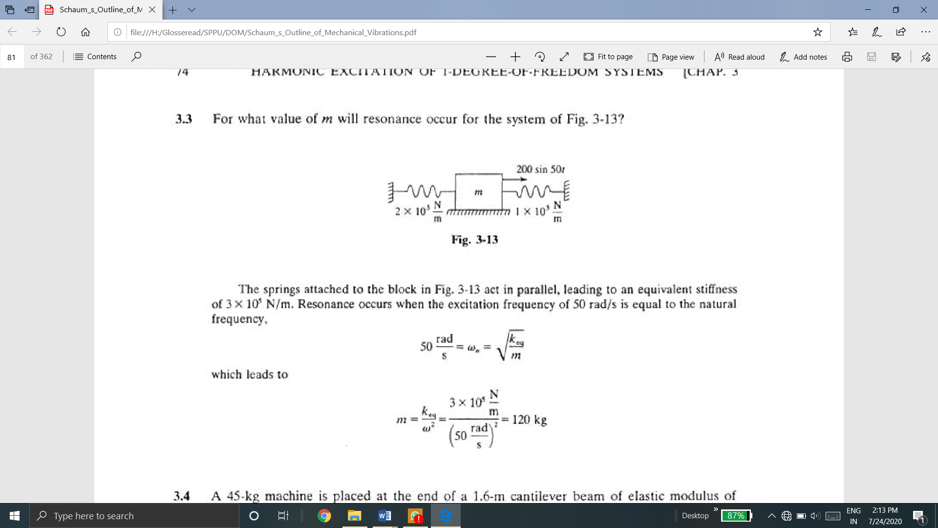
A6)
The springs attached to the block in Fig. act in parallel, leading to an equivalent stiffness of 3 X 10' N/m. Resonance occurs when the excitation frequency of 50 rad/s is equal to the natural frequency,
Q.7 A 45-kg machine is mounted on four parallel springs each' of stiffness 2 x l05 N/m. When the machine operates at 32 Hz, the machine’s steady-state amplitude is measured as 1.5 mm. What is the magnitude of the excitation provided to the machine at this speed?
A7)
The system's natural frequency
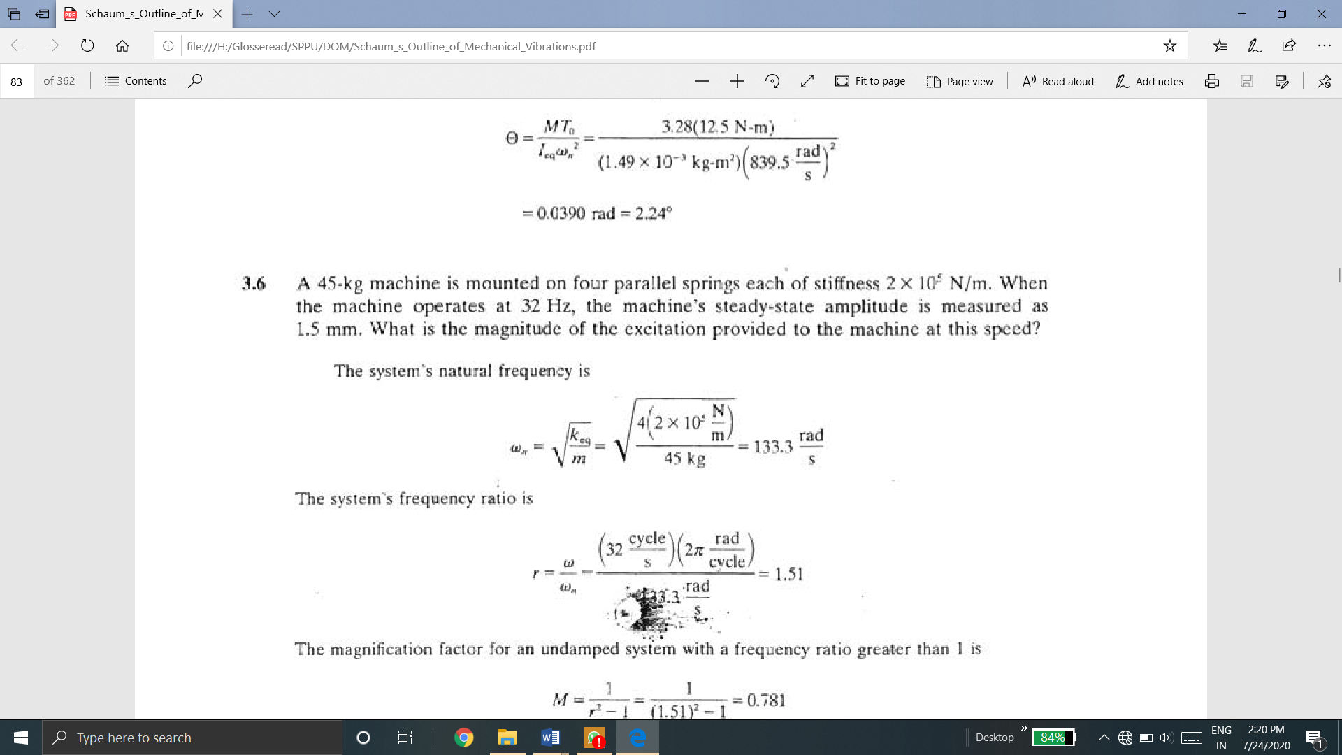
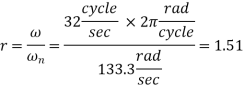
The system's frequency ratio is
The magnification factor for an undamped system with a frequency ratio greater than 1 is
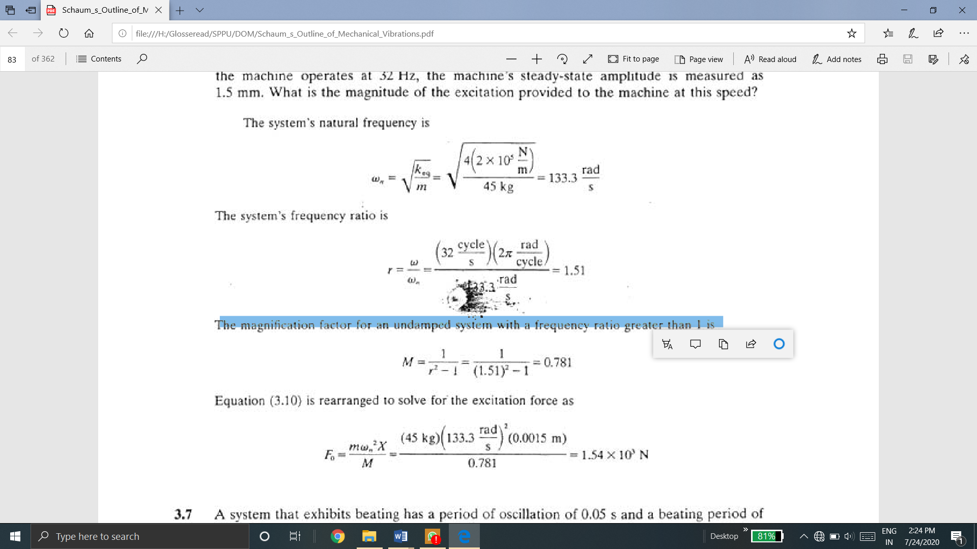
Q.8 A 1l0-kg machine is mounted on an elastic foundation of stiffness 2 x 10⁶ N/m. When operating at 150 rad/s, the machine is subject to a harmonic force of magnitude 1500 N. The steady-state amplitude of the machine measured as 1.9 mm. What is the damping ratio of the foundation?
A8)
The natural frequency of the system is
The magnification factor during operation is
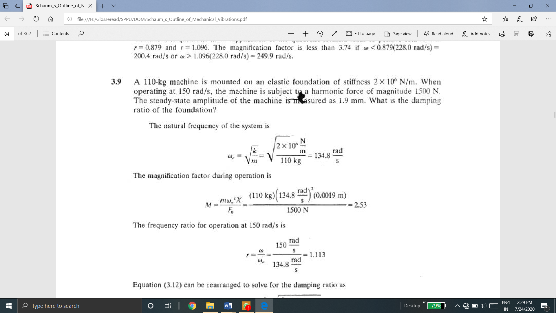
The frequency ratio for operation at 150 rad/s is

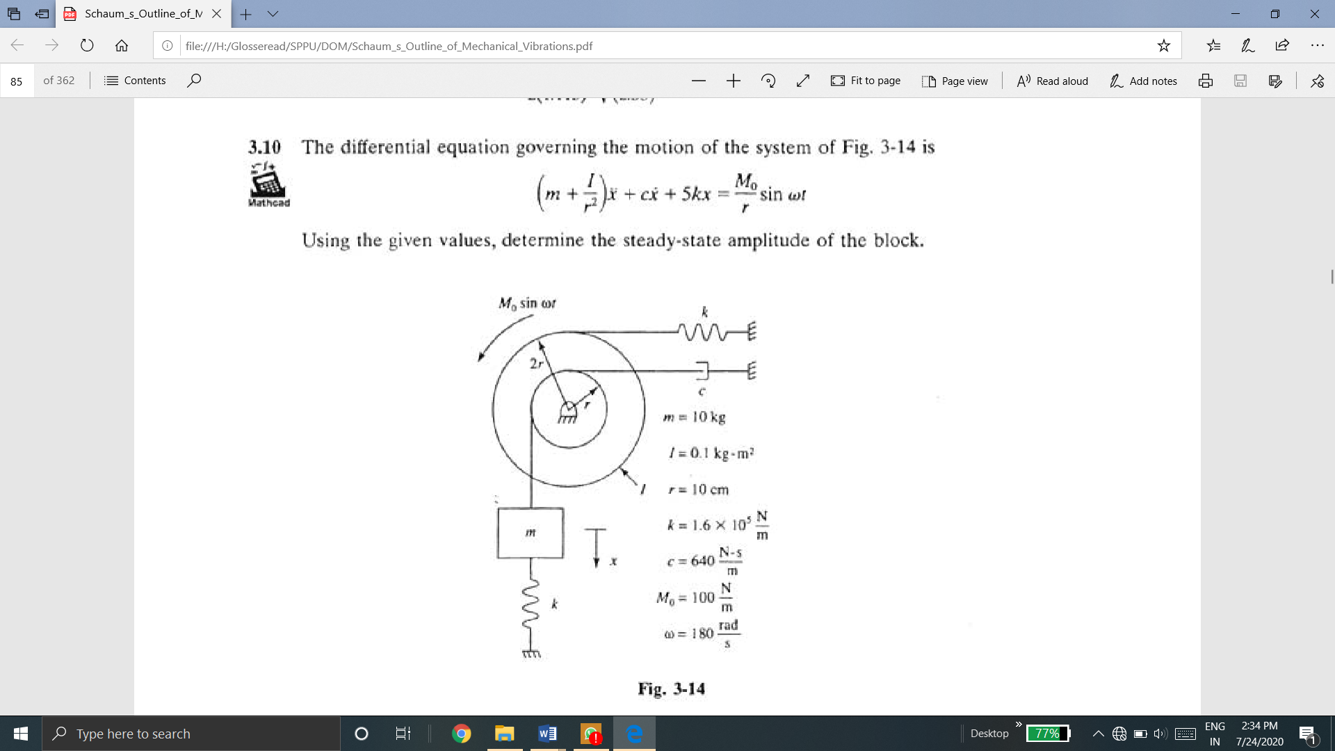
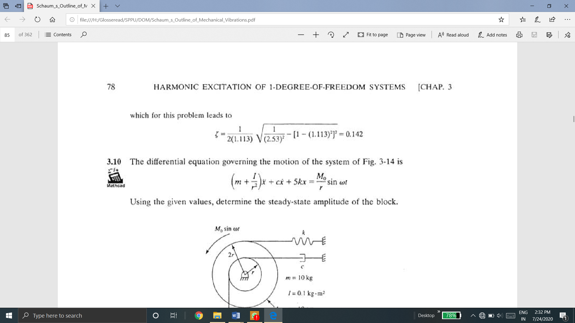
Q.9 The differential equation governing the motion of the system of Fig. is

Using the given values, determine the steady-state amplitude of the block.
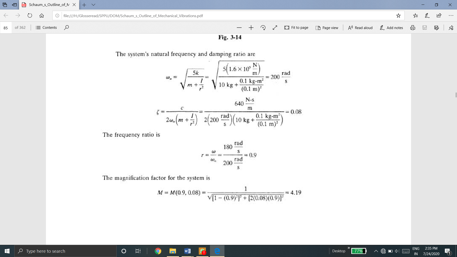
A9)
The system's natural frequency and damping ratio are

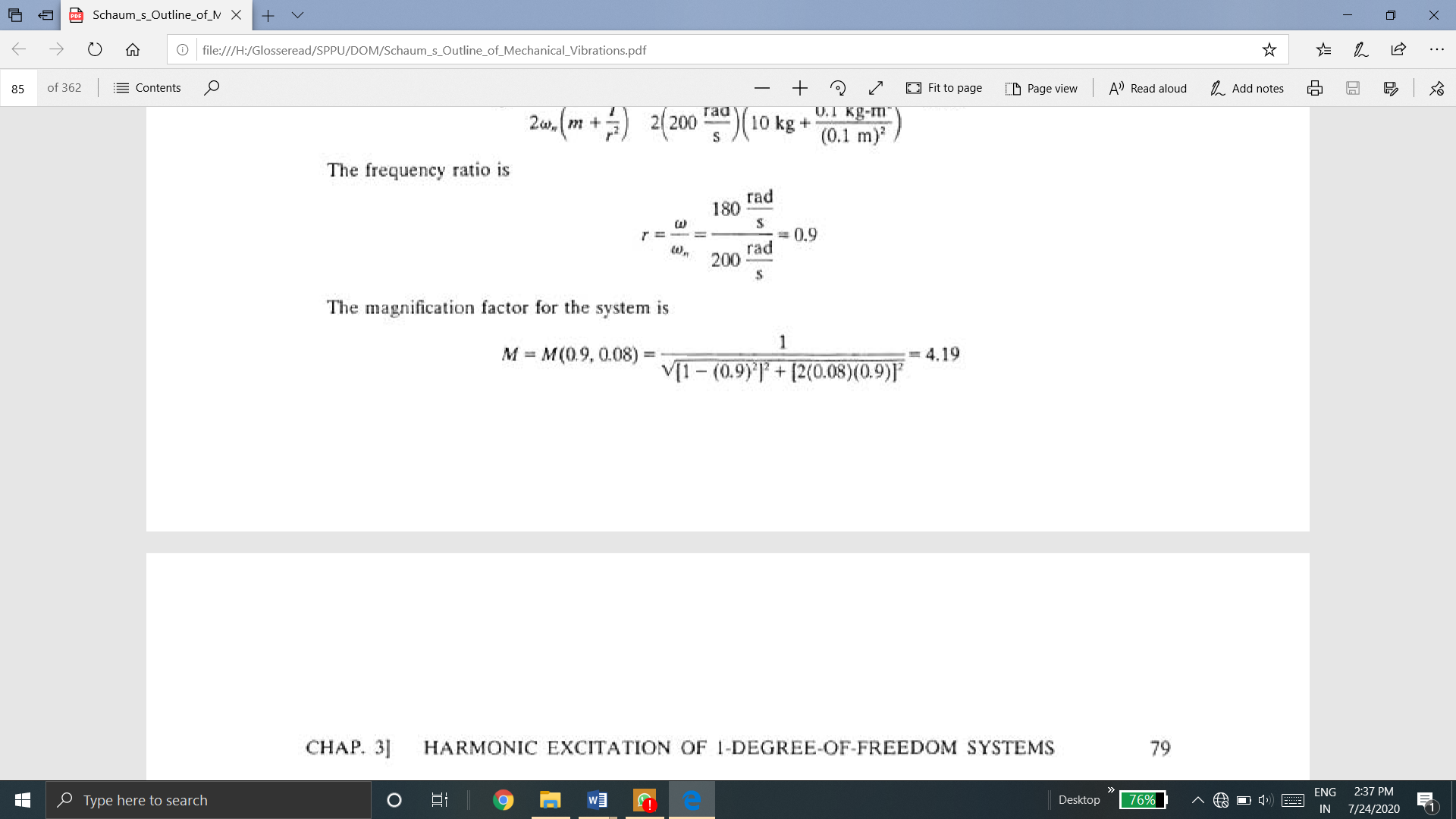
The frequency ratio
The magnification factor for the system is

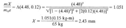
Q. 10 A 65-kg industrial sewing machine has a rotating unbalance of 0.15 kg-m. The machine operates at 125 Hz and is mounted on a foundation of equivalent stiffness 2 x 10⁶ N/m and damping ratio 0.12. What is the machine's steady-state amplitude?
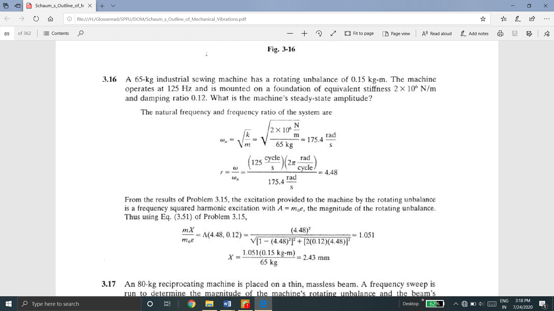
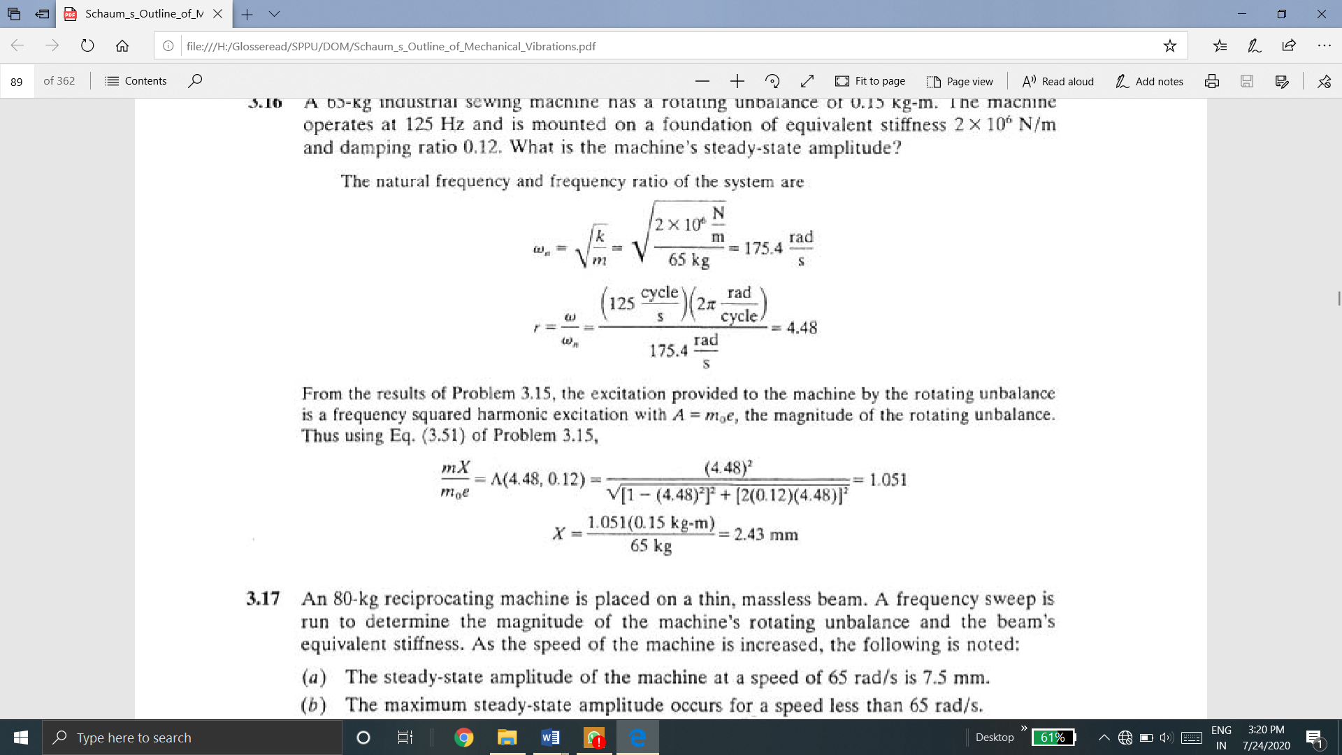
A10) The natural frequency and frequency ratio of the system are
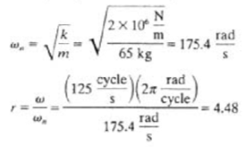
The excitation provided to the machine by the rotating unbalance is a frequency squared harmonic excitation with A = moe, the magnitude of the rotating unbalance.