Unit - 4
IIR Filter Design
Q1) For the following LTI system H(z)=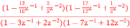 . Realise the cascade form IIR filter.
A1) H(z)=
The above function can be simplified as
H(z)=
Hence, using the above structure and placing the values of 
 …. And similarly,

Fig: Cascade Form realisation of IIR Filter
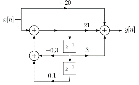
Q2) Draw block diagram for the function using parallel form H(z)=
A2) H(z)=
Writing above transfer function in standard form for parallel realisation we get
H(z)=-20+
The structure is shown below

Q3) Compare IIR and FIR filters?
A3)
Sr. No | IIR system | FIR system |
1. | IIR stands for infinite impulse response systems | FIR stands for finite impulse response systems |
2. | IIR filters are less powerful that FIR filters, & require less processing power and less work to set up the filters | FIR filters are more powerful than IIR filters, but also require more processing power and more work to set up the filters |
3. | They are easier to change “on the fly”. | They are also less easy to change “on the fly” as you can by tweaking (say) the frequency setting of a parametric (IIR) filter |
4. | These are less flexible. | Their greater power means more flexibility and ability to finely adjust the response of your active loudspeaker. |
5. | It cannot implement linear-phase filtering. | It can implement linear-phase filtering. |
6. | It cannot be used to correct frequency-response errors in a loudspeaker | It can be used to correct frequency- response errors in a loudspeaker to a finer degree of precision than using IIRs. |
Q4) Realise Direct form II and cascade form realizations of
A4) 


Direct form II

Cascade form
Q5) Realise the parallel form for 
A5) A partial fraction expansion of

The corresponding parallel form I realization is shown below

Q6) Draw block diagram for the function using parallel form H(z)=
A6)
H(z)=
Writing above transfer function in standard form for parallel realisation we get
H(z)=-20+
The structure is shown below
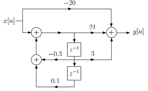
Fig: Parallel Realisation of H(z)=
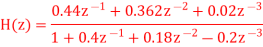
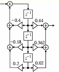
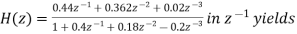
Q7) For the following LTI system H(z)= . Realise the cascade form IIR filter.
A7) H(z)=
The above function can be simplified as
H(z)=

Fig: Cascade IIR Form
Hence, using the above structure and placing the values of 
 …. And similarly,
Q8) For the system given y(n) - y(n-1) +
  y(n-2) = x(n) +
  x(n-1) realise using cascade form?
A8) The system transfer function is given as
H(z) = Y(z)/X(z)
Taking z transform of y(n) - y(n-1) +
  y(n-2) = x(n) +
  x(n-1)
Y(z) -  z-1Y(z) +
  z-2 Y(z) = X(z) +
  z-1 X(z)
H(z)= 
Again, simplifying the above function to get into standard cascade form we ca write
H(z) = 
= H1(z)+H2(z)
H1(z)= 
H2(z)= 
The final structure is shown below
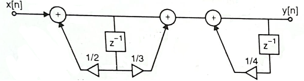
Fig: Cascade Form of H(z) = 
Q9) For the following LTI system H(z)= . Realise the cascade form?
A9) H(z)=
Writing the above in standard form for cascade realisation
H1(z)= 
H2(z)= 
The cascade structure is shown below
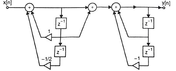
Fig: Cascade Form of H(z)=
Q10) Realize the system transfer function using parallel structure H(z)= 
A10) H(z)= 
Taking Z common and then dividing the above function to convert it into standard form for parallel realisation we get
H(z)=Z [  +
+ +
+ ]
]
The parallel structure is shown below

Fig: Parallel Realisation of H(z)= 
Q11) Realize the system transfer function using parallel structure H(z)= 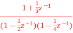
A11) Converting the above function to standard form using partial fraction technique
H(z)=  +
+ 
Solving for A and B we get
A= 10/3
B= -7/3
H(z) =  +
+ 
H1(z) = 
H2(z) = 
The parallel form realisation is shown below
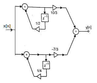
Fig: Parallel Realisation of H(z)= 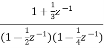
Q12) For the transfer function H(z) =  . Realise using cascade form?
A12) H(z) = 
Writing in standard form
H(z) = 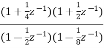
H1(z) = 
H2(z) = 
The cascade structure is shown below

Fig: Cascade Form of H(z) = 
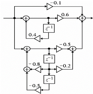
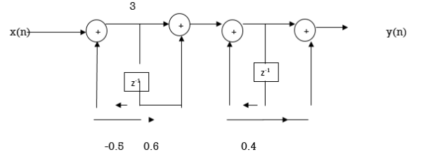
Q13) Obtain the direct form-I, direct form-II, Cascade and parallel form realization of the system y(n)=-0.1y(n-1)+0.2y(n-2)+3x(n)+3.6x(n-1)+0.6x(n-2)
A13) Direct Form I:

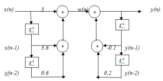
Direct form II:
From the given difference equation we have 

The above system function can be realized in direct form II
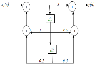
Cascade Form:


Parallel form:

Q14) Design an analog Butterworth filter that has a -2dB pass band attenuation at a frequency of 20 rad/sec and atleast -10 dB stop band attenuation at 30 rad/sec.
A14)
Given data:
Pass band attenuation αP= 2 dB;
Stop band attenuation αS= 10 dB;
Pass band frequency ΩP= 20 rad/sec.
Stop band frequency ΩS=30 rad/sec.
The order of the filter


Rounding off ‘N’ to the next higher integer, we get
N=4
The normalized transfer function for N=4.

To find cut off frequency


The transfer function for Ωc=21.3868,


Q15) Given specifications αp= 3dB,αs=16 dB, fP=1KHz and fS=2KHz. Determine the order of the filter using Chebyshev approximation. Find H(s).
A15) Given:
Step 1:
Pass band attenuation αp= 3dB,
Stop band attenuation αs=16 dB,
Pass band frequency fP=1 KHz=2π*1000=2000π rad/sec
Stop band frequency fS=2 KHz=2π*2*1000=4000π rad/sec
Step 2: Order of the filter


Rounding the next higher integer value N=2.
Step 3: The value of minor axis and major axis can be found as below


Step 4: The poles are given by


Step 5: The denominator of H(s):

Step 6: The numerator of H(s):

The transfer function 
Q16) Convert the analog BPF with system IIR filter  into a digital IIR filter by use of the backward difference for the derivative.
A16) 

Q17) For the analog transfer function  Determine H (z) using impulse invariant transformation if (a) T=1 second and (b) T=0.1 second.
A17)


Q18) Design a third order Butterworth digital filter using impulse invariant technique. Assume sampling period T=1 sec.
A18) For N=3, the transfer function of a normalized Butterworth filter is given by


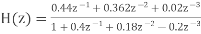
Q19) Apply impulse invariant method and find H(z) for 
A19) Given: The transfer function 
Sampling the function produces

Q20) Convert analog filter  into digital IIR filter using impulse invariant method.
A20) Analog filter 


Q21) Convert analog filter  into digital IIR filter whose system function is given above. The digital filter should have (
 ). Use impulse invariant mapping T=1sec.
A21) Given: Analog filter 


Q22) Apply bilinear transformation of  with T=1 sec and find H(z)
A22) Given: The system function 


Given T=1 sec.

Q23) Using the bilinear transformation, design a high pass filter, monotonic in pass band with cut off frequency of 1000Hz and down 10dB at 350 Hz. The sampling frequency is 5000Hz
A23) Given: Pass band attenuation ; Stop band attenuation
Pass band frequency 
Stop band frequency 

Prewarping the digital frequencies, we have


The order of the filter

The first order Butterworth filter for ΩC=1 rad/sec is H(s) = 1/S+1
The high pass filter for ΩC=ΩP=7265 rad/sec can be obtained by using the transformation.

The transfer function of high pass filter

Q24) Design a digital Butterworth filter satisfying the constraints

With T=1 sec using bilinear transformation
A24) Given data:
Pass band attenuation ; Pass band frequency
 ;
;
Stop band attenuation ; Stops band frequency
 ;
;
Step 1: Specifying the pass band and stop band attenuation in db

Step2. Choose T and determine the analog frequencies (i.e) Prewarp band edge frequency

Step3. To find order of the filter


Rounding the next higher value N=2
Step 4: The normalized transfer function

Step 5: Cut off frequency


Step 6: To find Transfer function of H(s):


Step 7. Apply Bilinear Transformation with to obtain the digital filter


Q25) Design a digital Butterworth filter satisfying the constraints

With T=1 sec using Impulse invariant method
A25) Pass band attenuation ; Pass band frequency
 ;
;
Stop band attenuation ; Stops band frequency
 ;
;
Step 1: Specifying the pass band and stop band attenuation in dB.

Step2. Choose T and determine the analog frequencies (i.e) Prewarp band edge frequency
Step3. To find order of the filter


Rounding the next higher value N=4
Step 4: The normalized transfer function

Step 5: Cut off frequency


Step 6: To find Transfer function of H(s):


Step 7: Using partial fraction expansion, expand H(s) into


Q26) Design a chebyshev filter for the following specification using bilinear transformation.

A26) Given data:
Pass band attenuation ; Pass band frequency
 ;
;
Stop band attenuation ; Stops band frequency
 ;
;
Step 1: Specifying the pass band and stop band attenuation in dB.

Step2. Choose T and determine the analog frequencies (i.e) Prewarp band edge frequency
Step3. To find order of the filter


Rounding the next higher integer value N=2
Step4. The poles of chebyshev filter can be determined by

Where,
 And calculate a, b,
 ,
, 


Step.5 Find the denominator polynomial of the transfer function using above poles.

Step 6 : The numerator of the transfer function depends on the value of N.
If N is Even substitute s=0 in the denominator polynomial and divide the result by Find the value. This value is equal to numerator

Step 7: The Transfer function is


Step 8: Apply bilinear transformation with to obtain the digital filter


Q27) Design a chebyshev filter for the following specification using impulse invariance method.

A27) Given data:
Pass band attenuation ; Pass band frequency
 ;
;
Stop band attenuation ; Stops band frequency
 ;
;
Step 1: Specifying the pass band and stop band attenuation in dB.

Step2. Choose T and determine the analog frequencies (i.e) Prewarp band edge frequency
Step3. To find order of the filter


Rounding the next higher integer value N=2
Step4. The poles of chebyshev filter can be determined by

Where,
 And calculate a, b,
 ,
, 


Step.5 Find the denominator polynomial of the transfer function using above poles.

Step 6 : The numerator of the transfer function depends on the value of N.
If N is Even substitute s=0 in the denominator polynomial and divide the result by Find the value. This value is equal to numerator

Step 7: The Transfer function is


Step 8: Using partial fraction expansion, expand H(s) into

Step 9: Now transform analog poles {Pk} into digital poles {epkT} to obtain the digital filter

Q28) Prove that 
A28)


Unit - 4
IIR Filter Design
Q1) For the following LTI system H(z)= . Realise the cascade form IIR filter.
A1) H(z)=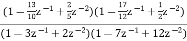
The above function can be simplified as
H(z)=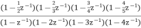
Hence, using the above structure and placing the values of 
 …. And similarly,

Fig: Cascade Form realisation of IIR Filter
Q2) Draw block diagram for the function using parallel form H(z)=
A2) H(z)=
Writing above transfer function in standard form for parallel realisation we get
H(z)=-20+
The structure is shown below
Q3) Compare IIR and FIR filters?
A3)
Sr. No | IIR system | FIR system |
1. | IIR stands for infinite impulse response systems | FIR stands for finite impulse response systems |
2. | IIR filters are less powerful that FIR filters, & require less processing power and less work to set up the filters | FIR filters are more powerful than IIR filters, but also require more processing power and more work to set up the filters |
3. | They are easier to change “on the fly”. | They are also less easy to change “on the fly” as you can by tweaking (say) the frequency setting of a parametric (IIR) filter |
4. | These are less flexible. | Their greater power means more flexibility and ability to finely adjust the response of your active loudspeaker. |
5. | It cannot implement linear-phase filtering. | It can implement linear-phase filtering. |
6. | It cannot be used to correct frequency-response errors in a loudspeaker | It can be used to correct frequency- response errors in a loudspeaker to a finer degree of precision than using IIRs. |
Q4) Realise Direct form II and cascade form realizations of

A4) 

Direct form II
Cascade form
Q5) Realise the parallel form for 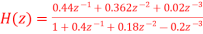
A5) A partial fraction expansion of

The corresponding parallel form I realization is shown below
Q6) Draw block diagram for the function using parallel form H(z)=
A6)
H(z)=
Writing above transfer function in standard form for parallel realisation we get
H(z)=-20+
The structure is shown below

Fig: Parallel Realisation of H(z)=
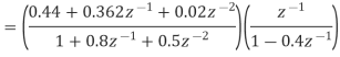
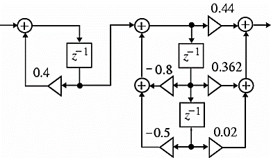
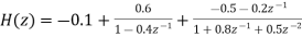
Q7) For the following LTI system H(z)= . Realise the cascade form IIR filter.
A7) H(z)=
The above function can be simplified as
H(z)=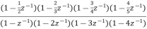
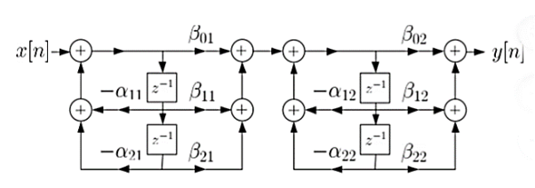
Fig: Cascade IIR Form
Hence, using the above structure and placing the values of 
 …. And similarly,
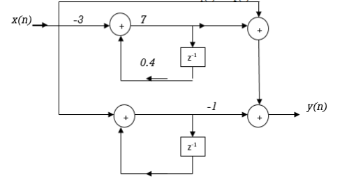
Q8) For the system given y(n) - y(n-1) +
  y(n-2) = x(n) +
  x(n-1) realise using cascade form?
A8) The system transfer function is given as
H(z) = Y(z)/X(z)
Taking z transform of y(n) - y(n-1) +
  y(n-2) = x(n) +
  x(n-1)
Y(z) -  z-1Y(z) +
  z-2 Y(z) = X(z) +
  z-1 X(z)
H(z)= 
Again, simplifying the above function to get into standard cascade form we ca write
H(z) = 
= H1(z)+H2(z)
H1(z)= 
H2(z)= 
The final structure is shown below

Fig: Cascade Form of H(z) = 
Q9) For the following LTI system H(z)= . Realise the cascade form?
A9) H(z)=
Writing the above in standard form for cascade realisation
H1(z)= 
H2(z)= 
The cascade structure is shown below

Fig: Cascade Form of H(z)=
Q10) Realize the system transfer function using parallel structure H(z)= 
A10) H(z)= 
Taking Z common and then dividing the above function to convert it into standard form for parallel realisation we get
H(z)=Z [  +
+ +
+ ]
]
The parallel structure is shown below
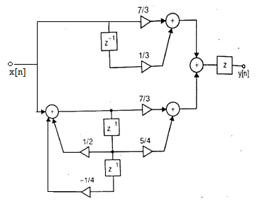
Fig: Parallel Realisation of H(z)= 
Q11) Realize the system transfer function using parallel structure H(z)= 
A11) Converting the above function to standard form using partial fraction technique
H(z)=  +
+ 
Solving for A and B we get
A= 10/3
B= -7/3
H(z) =  +
+ 
H1(z) = 
H2(z) = 
The parallel form realisation is shown below

Fig: Parallel Realisation of H(z)= 
Q12) For the transfer function H(z) =  . Realise using cascade form?
A12) H(z) = 
Writing in standard form
H(z) = 
H1(z) = 
H2(z) = 
The cascade structure is shown below
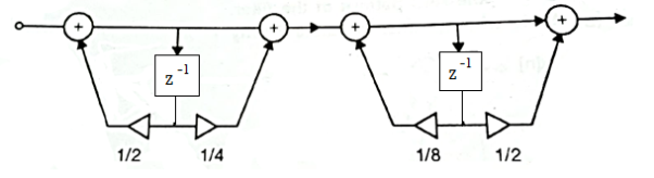
Fig: Cascade Form of H(z) = 
Q13) Obtain the direct form-I, direct form-II, Cascade and parallel form realization of the system y(n)=-0.1y(n-1)+0.2y(n-2)+3x(n)+3.6x(n-1)+0.6x(n-2)
A13) Direct Form I:


Direct form II:
From the given difference equation we have 

The above system function can be realized in direct form II

Cascade Form:

Parallel form:


Q14) Design an analog Butterworth filter that has a -2dB pass band attenuation at a frequency of 20 rad/sec and atleast -10 dB stop band attenuation at 30 rad/sec.
A14)
Given data:
Pass band attenuation αP= 2 dB;
Stop band attenuation αS= 10 dB;
Pass band frequency ΩP= 20 rad/sec.
Stop band frequency ΩS=30 rad/sec.
The order of the filter


Rounding off ‘N’ to the next higher integer, we get
N=4
The normalized transfer function for N=4.

To find cut off frequency


The transfer function for Ωc=21.3868,


Q15) Given specifications αp= 3dB,αs=16 dB, fP=1KHz and fS=2KHz. Determine the order of the filter using Chebyshev approximation. Find H(s).
A15) Given:
Step 1:
Pass band attenuation αp= 3dB,
Stop band attenuation αs=16 dB,
Pass band frequency fP=1 KHz=2π*1000=2000π rad/sec
Stop band frequency fS=2 KHz=2π*2*1000=4000π rad/sec
Step 2: Order of the filter


Rounding the next higher integer value N=2.
Step 3: The value of minor axis and major axis can be found as below


Step 4: The poles are given by


Step 5: The denominator of H(s):

Step 6: The numerator of H(s):

The transfer function 
Q16) Convert the analog BPF with system IIR filter  into a digital IIR filter by use of the backward difference for the derivative.
A16) 

Q17) For the analog transfer function  Determine H (z) using impulse invariant transformation if (a) T=1 second and (b) T=0.1 second.
A17)


Q18) Design a third order Butterworth digital filter using impulse invariant technique. Assume sampling period T=1 sec.
A18) For N=3, the transfer function of a normalized Butterworth filter is given by


Q19) Apply impulse invariant method and find H(z) for 
A19) Given: The transfer function 
Sampling the function produces

Q20) Convert analog filter  into digital IIR filter using impulse invariant method.
A20) Analog filter 


Q21) Convert analog filter  into digital IIR filter whose system function is given above. The digital filter should have (
 ). Use impulse invariant mapping T=1sec.
A21) Given: Analog filter 


Q22) Apply bilinear transformation of  with T=1 sec and find H(z)
A22) Given: The system function 


Given T=1 sec.

Q23) Using the bilinear transformation, design a high pass filter, monotonic in pass band with cut off frequency of 1000Hz and down 10dB at 350 Hz. The sampling frequency is 5000Hz
A23) Given: Pass band attenuation ; Stop band attenuation
Pass band frequency 
Stop band frequency 

Prewarping the digital frequencies, we have


The order of the filter

The first order Butterworth filter for ΩC=1 rad/sec is H(s) = 1/S+1
The high pass filter for ΩC=ΩP=7265 rad/sec can be obtained by using the transformation.

The transfer function of high pass filter

Q24) Design a digital Butterworth filter satisfying the constraints

With T=1 sec using bilinear transformation
A24) Given data:
Pass band attenuation ; Pass band frequency
 ;
;
Stop band attenuation ; Stops band frequency
 ;
;
Step 1: Specifying the pass band and stop band attenuation in db

Step2. Choose T and determine the analog frequencies (i.e) Prewarp band edge frequency

Step3. To find order of the filter


Rounding the next higher value N=2
Step 4: The normalized transfer function

Step 5: Cut off frequency


Step 6: To find Transfer function of H(s):


Step 7. Apply Bilinear Transformation with to obtain the digital filter


Q25) Design a digital Butterworth filter satisfying the constraints

With T=1 sec using Impulse invariant method
A25) Pass band attenuation ; Pass band frequency
 ;
;
Stop band attenuation ; Stops band frequency
 ;
;
Step 1: Specifying the pass band and stop band attenuation in dB.

Step2. Choose T and determine the analog frequencies (i.e) Prewarp band edge frequency
Step3. To find order of the filter


Rounding the next higher value N=4
Step 4: The normalized transfer function

Step 5: Cut off frequency


Step 6: To find Transfer function of H(s):


Step 7: Using partial fraction expansion, expand H(s) into


Q26) Design a chebyshev filter for the following specification using bilinear transformation.

A26) Given data:
Pass band attenuation ; Pass band frequency
 ;
;
Stop band attenuation ; Stops band frequency
 ;
;
Step 1: Specifying the pass band and stop band attenuation in dB.

Step2. Choose T and determine the analog frequencies (i.e) Prewarp band edge frequency
Step3. To find order of the filter


Rounding the next higher integer value N=2
Step4. The poles of chebyshev filter can be determined by

Where,
 And calculate a, b,
 ,
, 


Step.5 Find the denominator polynomial of the transfer function using above poles.

Step 6 : The numerator of the transfer function depends on the value of N.
If N is Even substitute s=0 in the denominator polynomial and divide the result by Find the value. This value is equal to numerator

Step 7: The Transfer function is


Step 8: Apply bilinear transformation with to obtain the digital filter


Q27) Design a chebyshev filter for the following specification using impulse invariance method.

A27) Given data:
Pass band attenuation ; Pass band frequency
 ;
;
Stop band attenuation ; Stops band frequency
 ;
;
Step 1: Specifying the pass band and stop band attenuation in dB.

Step2. Choose T and determine the analog frequencies (i.e) Prewarp band edge frequency
Step3. To find order of the filter


Rounding the next higher integer value N=2
Step4. The poles of chebyshev filter can be determined by

Where,
 And calculate a, b,
 ,
, 


Step.5 Find the denominator polynomial of the transfer function using above poles.

Step 6 : The numerator of the transfer function depends on the value of N.
If N is Even substitute s=0 in the denominator polynomial and divide the result by Find the value. This value is equal to numerator

Step 7: The Transfer function is


Step 8: Using partial fraction expansion, expand H(s) into

Step 9: Now transform analog poles {Pk} into digital poles {epkT} to obtain the digital filter

Q28) Prove that 
A28)


