UNIT 3
Hydroelectric power plant
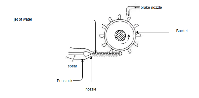
Q1) Explain the working of Pelton wheel turbine with neat diagram in hydro power plant.
A1)
Palton wheel turbine:-
● Pelton wheel is impulse type turbine
● It is used at high head (90-1100m)
● It is specific speed is 10 to 40 m
● It consists of the rotor equipped with elliptical pockets along the whole peripheri
● Tiles and wheel turbine consists of runner, bucket, nozzle, needle value and shaft.
● The buckets are made up of stainless steel cast iron and bronze material.
● In this type of turbines one or two jets are used to force the water through buckets
● The nozzle are used to increase the pressure of water flow towards turbine.
● The short is useful for mechanical coupling with generator
● The direction of flow of water is tangent.
Q2) Compare Impulse turbine with Reaction turbine in hydro power plant.
A2)
Comparison between Impulse and Reaction Turbine
Sr. No. | Impulse turbine | Reaction turbine |
1) | It works on the principle of impulse | It works on principle of impulse as well as reaction |
2) | Water from the nozzles comes in the form of jet which impinges on the bucket of runner. | Water is guided by the guide blades to flow over the moving vanes.
|
3) | Flow of water over the runner is at constant atmospheric pressure | The flow of water over the runner is under the pressure which slowly decreases from inlet to outlet |
4) | All the available head is first converted into kinetic energy in nozzle | Only a part of available head is converted into kinetic energy in the guide vanes |
5) | Possible to regulate the flow of water without loss. | It is not possible to regulate the flow of water without loss. |
6) | Suitable for high heads. | Suitable for medium or low heads. |
7) | The work is done due to change in kinetic energy of jet. | Most of the work is done due to the change in pressure head and a very small work is done due to the change in kinetic energy. |
Q3) Compare Francis turbine with Kaplan turbine in hydro power plant.
A3)
Comparison between Francis and Kaplan Turbine
Sr. No. | Francis | Kaplan |
1) | Water enters the runner radially | Water enters the runner axially. |
2) | Only guide pens are adjustable | Guide vanes and moving vanes are both adjustable |
3) | Frictional resistance is high | Frictional resistance is less due to less number of vanes . |
4) | Number of blades are 16 to 24 is general | Number of blades are generally 3 to 4 |
5) | It is big in size | It is compact in size |
6) | High efficiency is obtained only at high loads | High efficiency is obtained even at part loads |
7) | Specific speed range 50 to 250 | Specific speed range 250 to 850 |
Q4) Write a note on selection of turbine.
A4)
The selection of a water turbine depends upon our factors such as working head, available discharge, speed, output and nature of load.
The effective head under which the turbine is to operate give the first Guide to the selection of the type of turbine.
For very high head i.e. 500 metres and above, Pelton turbine is usually employed.
Reaction turbines are not suitable for such type heads as due to high velocity of water, there will be a rapid wear and friction losses.
For medium heads that is about 30 metres and below 500, Francis turbine is usually adopted but impulse turbine may also be adopted even at the expense of efficiency.
For low heads i.e. below 70 metres, popular type of turbine is used.
In case of considerable variation in heads and load Kaplan turbine gives improved efficiency as compared to to the fixed blade propeller turbine.
Even for the same head to different types of turbines may be employed. for example for a head of 200 either of the pelton or Francis turbine can be used.
It is a general practice to select a runner of higher specific speed.
For a larger output but at low head, a runner of highest specific speed is used to keep the size of the turbo alternator and power house smaller and economical.
Q5) What are the factors used to select the site of hydro power plant?
A5)
The factors that should be considered.
For selecting the side of HP’s:-
1) Quantity of water required:-
The HPS totally runs on water so ample of water is should be continuously available throughout the year.
2) Hilly area required:-
For storage of ample quantity of water on both side of the dam hilly area of strong mountains are required for storage.
3) Civil work:-
It should have a strong foundation and the cost of foundation should be as low as possible.
4) Large catchment area :-
Large catchment area is required so that the water in it should never for below the minimum level.
5) Transportation facility:-
For the workers and civil material required, better transportation facility should be their.
6) Near to load centre:-
To reduce the cost of transmission and distribution the plant should be located near the load centre.
7) Availability of material:-
At the time of erecting the dam and powerhouse, a huge amount of civil material should be easily available without storage.
8) Area free from earthquake:-
Area should be free from earthquake because flood may occur.
9) Accommodation facility:-
For operational and maintenance staff better facility of accommodation should be provided at the reasonable rate.
10) Future expansion:-
For increasing per megawatt capacity of plant, the space should be available for the future expansion.
Q6) In hydro power plants classify hydraulic turbines.
A6)
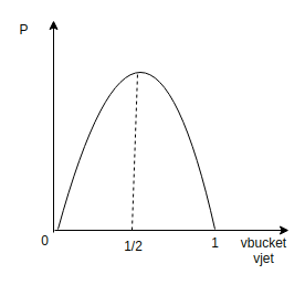
Turbine
Pelton wheel turbine (impulse)
V bucket=
P =f impulse ×v bucket
Types of turbines:-Turbines in the HPS acts as prime mover of the generator the classification is as follow.
a) According to type of flow of water
● Axis along the shaft of machine.
● Axis along the radius
● Axis along the tangential direction
b) According to action of fluid
● Impulse
● Reaction
Q7) Explain the function of turbine governors.
A7)
The function of the turbine governors are
● It should control the speed of turbine when load fluctuates at synchronous speed of the generator.
● It helps to start and shutdown the turbine unit by opening and closing the nozzles of the pelton wheel and gales in case of reaction turbine.
Governing mechanism:-
● The rate of discharge of the water in the turbine is adjusted by changing the floor area of the nozzle in order to meet or fulfill the changing load requirements with the help of governor mechanism.
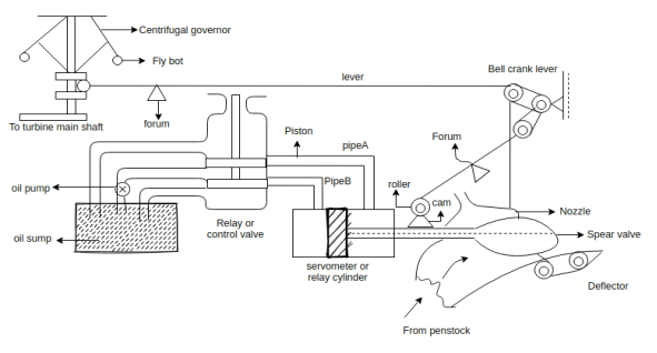
Consider a case,
When a load on the generator increases then the speed of the generator and that of turbine will decrease.
● As the governor is driven by a turbine shaft its speed will also decrease as a result the fly ball of the governor will move in words because the centrifugal force on the Bola decreases.
● Show the sleeve of the governor will move in the downward direction.
● The downward motion of the sleeve will be transferred to the main lever through its fulcrum.
● Hence piston rod of the relay valve will move upward and simultaneous will bell and crank lever will also move upward.
● Due to the upward motion of piston rod of control e valve, the pressurized oil flows through pipe A through the railway cylinder and exerts a force on face. The piston of servo motor.
● It moves the piston to the left hence the square rod with its valve will also move towards left direction.
● It will increase the nozzle area and the rate of flow of water to the turbine increases.
● Hence input to the turbine and ultimately its speed increases.
● When piston of the servo motor moves towards left, the oil present in the cylinder towards face B is transferred to the oil. Sum p through pipe B and relay valve.
● when the speed of the turbine finally adjusted to the normal speed the system returns to the original position.
● Exactly opposite will be the case when lord on the generator.
Q8) Write a short on Dam.
A8)
DAM
● It is used to store the water
● It provide suitable head to the stored water.
● This stored water is used throughout year to run HPS
● Dam is made up of cement concrete and sand material.
● When heavy rainfall occurs the door of dam others to follow the water.
● Dam is one of the main structure in the HPS it is a thick wall made of RCC ,earth ,and stone masonary
● To increase the water level for storage of high head
● It is usually built across a river
● The factor that should be considered for selection of site for dam
a) Material for construction of dam should be easily available and accessible for site.
b) Soil bearing capacity should be high
c) Site should have transformation and communication facility
d) It should be located at the neck of river.
e) It should be away from earthquake zone.
f) It should be economical to construct
g) Good catchment area should be available on upstream side.
Classification of dam
Field dams.
● Earth dam
● Backfield dam
Masonry dams
● Gravity dam
● Buttress dam
● Arch dams.
Timber dams.
Q9) Write a short note on Water hammer and surge tank
A9)
Reduction in load on the generator causes the Governor to close the turbine gates and thus create an increased pressure in the penstock. This may result in water hammer phenomenon and may need pipes of extraordinary strength to which stand it otherwise penstock may burst.
To avoid this positive water hammer pressure, some means are required to be provided for taking the rejected flow. this may be accomplished by providing a small storage Reservoir or tank for receiving the rejected flow and thus relieving the conduit pipe of excessive water hammer pressure. Is storage Reservoir called the surge tank is usually located at close to the power station at possible, preferably on ground to reduce the height of the tower.
A decrease in load demand causes rise in water level in the Surge tank. This produces a retarding head and reduces the velocity of water in the penstock.
Increase in load on the plant causes the Governor to open the turbine Gates in order to allow more water to flow through the penstock to supply the increased the load and there is a tendency to cause a vacuum or negative pressure in the penstock.
Again under such conditions the additional water flows out of the surge tank.
Thus surge tank helps in stabilizing the velocity and pressure in the penstock and reduces water hammer and negative pressure or vacuum.
Q10) Hydroelectric power station is supplied from a reservoir of capacity  at the head of 150. Determine the total energy available in kWh if the overall efficiency of the plant is 70%.
A10)
Water head, H=150 m
Quantity of water, 
Density of water, w=1000 kg/
Overall efficiency of the plant, =70%=0.7
Electrical energy available=wQH watt-secs


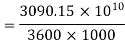
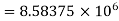 kWh
kWh
Q11)Hydroelectric power plant operates under an effective head of 50 m and a discharge of 94  . Determine the power developed.
A11)
Discharge, 
Head, 
Density of Water, 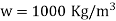
Power developed, 


Q12) The mean monthly discharge at a particular site is given below:
Month | Discharge in  | Month | Discharge in  |
January | 200 | July | 1600 |
February | 400 | August | 1200 |
March | 600 | September | 2000 |
April | 2400 | October | 1200 |
May | 1200 | November | 800 |
June | 1800 | December | 400 |
Draw the hydrograph, flow duration curve and mass curve.
Determine the average inflow and the power that can be developed at an effective head of 90 m. Determine the capacity of the storage Reservoir based on the above 1 year data neglecting the losses due to seepage, evaporation etc. Assume overall generation efficiency to be 80 %.
A12)
The average in flow is obtained by adding the 12 monthly charges and dividing by 12
Average inflow, 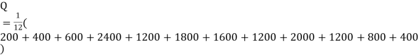

Power developed, 


The hydrograph is plotted using the table given in the numerical.
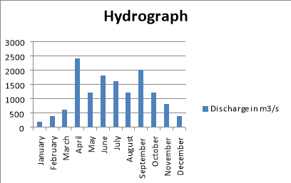
From the hydrograph plotted, the flow duration curve can be drawn by finding the length of time, during which certain flows are available. This information is tabulated in the following table and the flow duration curve is plotted.
Discharge in m3/s | Duration in Months | Percentage Time |
200 | 12 | 100.00 |
400 | 11 | 91.67 |
600 | 9 | 75.00 |
800 | 8 | 66.67 |
1200 | 7 | 58.33 |
1600 | 4 | 33.33 |
1800 | 3 | 25.00 |
2000 | 2 | 16.67 |
2400 | 1 | 8.33 |
During January, February and March, the discharge being less 950, e 750 E and 550 the excess discharge during.
The excess discharge during April, May, June, July, August, September and October would completely filled the reservoir so that the deficiency during November and December of the Year and January, February and March of next year can be made by drawing water from reservoir.
The storage capacity of the Reservoir is evidently the excess flow during April, May, June, July, August, September and October i.e.
Total of 3350 second-meter-months.
To obtain mass curve the total second meter months at the end of various months of the Year are determined as below.
Months | Discharge in m3/s | Accumulative Run off in second-meter-months |
January | 200 | 200 |
February | 400 | 600 |
March | 600 | 1200 |
April | 2400 | 3600 |
May | 1200 | 4800 |
June | 1800 | 6600 |
July | 1600 | 8200 |
August | 1200 | 9400 |
September | 2000 | 11400 |
October | 1200 | 12600 |
November | 800 | 13400 |
December | 400 | 13800 |
Q13) Give the functions of following components
(I) Spillways
(II) Waterway and penstock
A13)
I) Spillways
● Spillways are provided to discharge the flood water during the rainy season if the water level raises above the design the maximum level in the reservoir solid gravity or over all spillways.
1) Excess water above the full reserve air flows over the crest in the form of rolling sheet.
2) This spillway is built within the body of dam.
3) The water bucket provided at the end of spillway changes the direction of fast moving water and its energy is destroyed
II) Waterway and penstock
● To water way is used to flow the water from dam to the power house.
● It includes canal and penstock (closed pipe) or (tunnel).
● Penstocks are made up of steel or reinforced can concrete (which are designed to withstand the high pressure)
● Paint stocks are supported by anchors.
● Sharp bends should not be there into the penstock because it can create hydraulic losses.
Q14) Explain in detail general arrangements and operation of hydropower plant
A14)
The thief requirement for hydroelectric power plant is the availability of water in huge quantity at sufficient head and this requirement can be met by constructing a dam across a river or lake. The schematic arrangement of a typical hydroelectric power plant is shown in figure.
An artificial storage reservoir is formed by constructing a dam across the river or lake and a pressure tunnel is taken off from the reservoir to the wall house at the start of the penstock.
The valve house contains main sluice valves for controlling water flow to the power station and automatic isolating valves for cutting off water supply in case the penstock bursts.
A Surge tank is also provided just before the house for better regulation of water pressure in the system.
From the reservoir the water is carried to valve house through pressure tunnel and from valve house to the water turbine through pipes of large diameter made of steel for reinforced concrete called the penstock.
The water turbine converts hydraulic energy into mechanical energy and the alternator coupled to the water turbine converts mechanical energy into electrical energy.
Function of different components used in HPS
Catchment area
● By collecting the rainwater to surrounding heavily area it is stored in one place this is known as catchment area.
● More is the catchment area larger will be storage
Reservoir
● The function of reserve air is to store water near dam
● The water is useful to drive the water turbine
● The deserve air is useful to provide a head of stored water
Track rash
● It is used in HPS to filter the water before it flows towards turbine
● The unwanted impurities like fish, plastic present in the stored water should be avoided to flow towards turbine
Head race level
● The water surface in the reserve year up to the dam is called as head race level
Q15) Give the Classification of Hydroelectric Power Plant and explain in detail Storage type plants.
A15)
HPS are classified as follow
a) Based on availability of head
● Low head plants.
● Medium head plants
● High head plants
b) Based on the nature of load
● Base load plants
● Peak load plants
c) Based on quantity of water available
● Run of river plants without Pondage
● Storage type plants
● Pumped storage peak load plants
● Mini and micro hydro plants
Storage type plants (reserve air plants)
● This type of HPS is different from the above mentioned plant
● In this type reserve air is provided this reserve near is contains ample quantity of water during rainy season and useful throughout the year
● Such type of plant have better capacity and can be used as base load plants


