UNIT 1
THERMAL POWER PLANTS
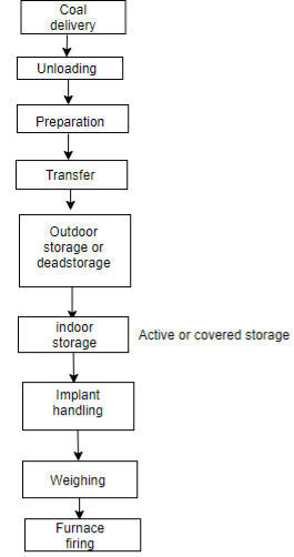
Q1) Draw a block diagram of fuel handling system in thermal power plant indicating the stages involved.
A1)
The steam power plant usually operates on the following type of fuels
1) Solid fuel (i.e. coal)
2) Liquid fuel (i.e. oil)
3) Gaseous fuel (i.e. natural gas)
A major amount of operating cost of Tps involves the cost of fuel handling system. It depends on the location of plant.
1) Storage of fuel
2) Rate at which fuel is bum.
Coal transportation:-
1) A large amount of coal per day is needed for the large capacity power plants.
2) The coal is transferred from the coal mines to the site of power station.
Following are methods:-
1) Sea or river
2) By rail
3) By roadways
4) By pipelines
3) The coal is transported by ships to the power plant which is nearer to the sea share.
4) For the power plants away from mines the coal is transported to main or nearest station. From their by small rail lines or by roadways, the coal is transported to the small power plants.
5) The coal transportation by pipeline is the most economical and speedy method.
Requirements of good coal handling plant:-
1) It should be reliable.
2) It should require less maintenance.
3) It should be simple in construction.
4) It should have minimum where in running equipments. Due to the action of coal particles.
5) There should be the continuous supply of coal as demand of power plant.
Q2) Explain rankine cycle with advantages over carnot cycle.
A2)
Actual Rankine cycle
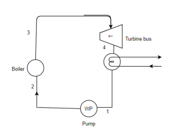
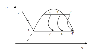
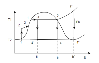
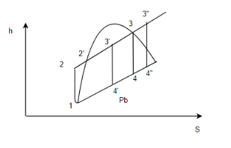
The Rankine cycle is an ideal reversible cycles for steam power plant corresponding to carnot cycle.
The cycle consists of following processes.
Process 1-2
Pumping of feed water to boiler from pressure Pb to pl, compression process is reverse adiabatic.
Process 2-3
Conversion of feed water into steam at constant pressure equal to boiler pressure p1 the heat supplied during the process is q1.
Process 3-4
Reversible adiabatic (isentropic expansion) of the system in turbine from boiler pressure p1 to back pressure Pb (condenser pressure Pb or exhaust pressure) Turbine work is (
Process 4-1
The steam is condensed at constant pressure in condenser steam rejects the latent heat of vaporization to the cooling water=
Q3) Write the types of boiler.
A3)
Boiler classification:-
Boiler is a device used for producing steam under pressure.
Boilers are classified on various basis:-
1) Depending upon position of water and flue gases.
A) Fire tube boiler
In this type of boilers hot gases or flue gases from the furnace are passed through the tubes surrounded by the water outside which is to be evaporated.
Eg.
Cochron boiler,
Lancashire boiler
Locomotive boiler
B) Water tube boiler
In this boilers water to be evaporated passes through the tubes and gases from the furnace are passed over the furnace of the tubes.
Eg
Babcock
Willcocks
Stirling
2) Depending upon the position of furnace
A) Internally fired boilers
In this the furnace is inside the body of boiler shell
Eg
Loncashire
Locomotive
B) EXTERNALLY FIRED BOILERS
In this the furnace is outside the boiler shell.
Eg
Stirling
Babcock willcocks
Loeffler
3) Depending upon the position of axis of the boiler
A) Vertical boiler:-
In this type axis of the boiler shell is in vertical plane.
B) Horizontal boilers:-
In this type axis of the boiler shell is in horizontal plane.
4) depending upon the service in which the boilers are like in stationary portable
Eg
Locomotive
Marine
5) Depending upon the sources of the heat
Sources of heat may be due to
A) Heat generated due to combustion of solid liquid and gaseous fuel.
B) Hot waste gases or electrical energy or atomic energy.
6) According to the method of circulation of water and steam
A) Natural circulation:-
In case of natural circulation of steam boilers are the water is circulated by natural circulation convection which are set up due to heating of water.
Water flows from high density to low density.
Eg.
Babcock will cocks boilers
B) Forced circulation:-
In forced circulation of boiler, the water is circulated with the help of centrifugal action pump driven by external source of power. Search method of water circulation is usually employed in high pressure boilers.
Eg
Lamont boiler
Loeffler boiler
7) According to the nature of drought employed
When the fuel is burnt on the furnace of boiler due to natural circulation of air, the drought is called as natural or chimney draught.
If the air is circulated driven by external source of power is called as artificial draught.
8) According to the pressure of steam generated
The boilers which generates steam at less than 20 bars pressure are caused as low pressure boiler.
Eg .
Cochron
Lancashire
Locomotive
Q4) With the help of diagram explain working and main parts of thermal power plant.
A4)
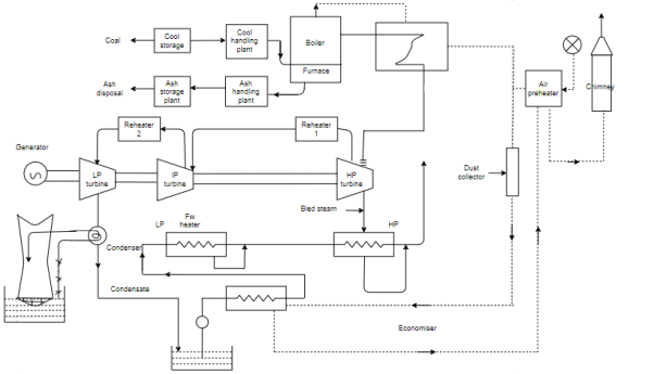
Cool and ash circuit:-
Coal is first collected in coal storage system by coal handling process through fuel handling devices. Then this coal is supplied to boiler furnace after combustion of coal, ash is collected from the boiler furnace.
Through ash handling equipment it is removed to ash storage yard.
Air and gas circuit:-
Air from the atmosphere is supplied to a combustion chamber of the boiler through the action of force draught/ or induced draught fan. First year is passed through air preheater where it is heated by the heat of flue gases(which are then pass through chimney) then this air is passed through the boiler. High temperature flue gases which are formed in the combustion chamber of the boiler are used for transfering heat to the feed water and steam in the boiler tubes and steam in the super heater tubes.
The flue gases caring ash are passed through dust collector device in order to remove the ash and finally these are passed over economiser and air preheater.
Feed water and steam circuit:-
Steam generated in the boiler tubes and superheated in super heater tubes is fed to high pressure.  turbine to develop mechanical power when steam is is expanded in hp turbine.
1) A part of steam is bled for feed water heating in Hp feedwater heater.
2) And remainder is passed through reheater for reheating the steam.
These steam is now passed through the intermegit pressure turbine for further expansion. After expansion,
1) Part of steam is bled for feed water heating in Lp feedwater heater.
2) And remainder is given to low pressure turbine for further expansion.
Mechanical power developed by turbine is supplied to alternator (generator) where mechanical energy is converted to electrical energy.
Cooling water circuit:-
We have to condense the steam of exhaust through condenser the quantity of cooling water required to be circulated in the condenser is about 50 kg of cooling water per kg of steam.
This water is taken from various resources live river, lake or see, if sufficient quantity of water is not available the heated water (coming out from the condenser) is cooled in the cooling towers by elaborated cooling and it is re-circulated to cooling. Condensers maybe
1) Direct or jet type condenser.
2) Indirect type or surface type of condenser.
Jet condenser or direct condenser:-
In this type the exhaust steam and the cooling water comes in direct contact and as a result steam is condensed.
The temperature of the condensate and the coolant is same i.e. while leaving the condenser. So it is called as direct contact condensers. These condensers can’t be used more because condensate collected can't be reused due to impurities of the coolant in the condenser. So it will reduce the efficiency of boiler because the impure condensate will corrode the plant tubes and will give rise to scale formation in the boiler tubes.
If the condensate is to be used as feed water to the boiler it is essential that the cooling water is treated before it is supplied to the condenser such condensers are used for small power plants.
Surface condensers (in direct type)
These are used in plants where the tubes water flows in the tubes and exhaust steam is passed over the tubes.
Q5) Explain Thermal process of feed water treatment.
A5)
Thermal process (treatments):-
1) The dissolved gases like  air and other gases are responsible for corrosion because these gases reacts with impurities and forms acids.
2) So the gases are removed from the water before supplied to boiler by the methods of thermal treatments.
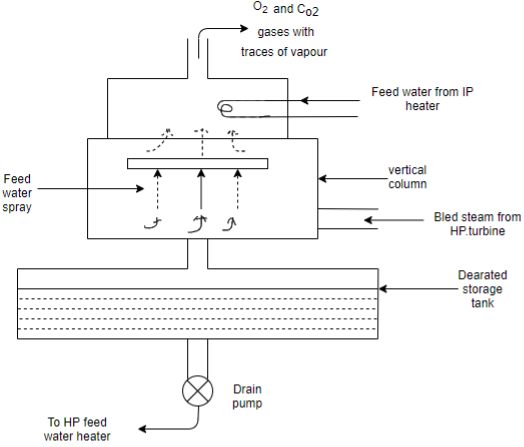
A) DEARATION PROCESS:-
1) It is also called as degasification process as mentioned above it is the most important method of feed water treatment. For the removal of 
2) Because this gases make the water corrosive (as they react with metal to form iron oxide)
3) the presence of these dissolved gases in water decreases with increase in the temperature and their magnitude becomes almost negligible at about 100°C (saturation temperature of steam at atmospheric pressure)
4) Feed water from ( heater is spread from the top and the bleed system Hp turbine from the bottom of the dearator.
5) These two comes in direct contact and as a result steam condenser and feed water is heated.
6) The dissolved gases along with vapours are released during heating and removed from the dearator from top connection.
7) The dearator works at about 1 to 1.25 bar (medium pressure) (40-50) bar and dearator works at about 5-8 bar for the high pressure boiler (greater than or equal to 100°)
Q6) Classify the Feed water treatments.
A6)
1) Mechanical
2) Thermal
3) Chemical
1) Mechanical:-
1) Sedimentation
2) Coagulation (Al, sulphate, sodium) etc.
3) Filtration
2) Thermal
1) Dearation process
2) Evaporation process
3) Chemical
1) Internal
2) External
Q7) Explain Hydraulic ash handling plant with the Requirements of Ideal ash handling plants.
A7)
Requirements of Ideal ash handling plants.
1) Plant should be noiseless as far as possible.
2) Capital investment operation and maintenance charges should be low.
3) Equipments should be corrosion and wear resistance.
4) Equipments should be able to handle clinkers, dust particles, soot dust etc. smoothly

1) Hydraulic ash handling plant
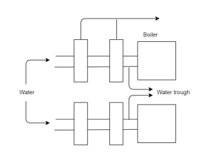
1) Ash from the furnace grade fails into the system of water (having high velocity) and it carries ash to sums.
2) In sums water and ash are separated.
3) The ash is them loaded to wagons or trucks by means of belt conveyors or grab bucket and transferred to dumpsite (materials used for trough and sums should be corrosion and where resistance because when ash dissolved into the water it forms acid).
Advantages:-
1) Used for large power plants
2) Clean, dust less and totally indoor.
3) Doesn't harm working people in the system.
Q8) Explain with diagram Pneumatic ash handling systems
A8)
Pneumatic ash handling systems:-
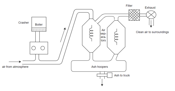
1) Ash from the boiler furnace. Falls into the crusher where large as particles are divided into small ash particles.
2) A high velocity air stream created by an exhausted carries and ash and dust particles to primary separators.
3) ash is collected in ash hooper the air with left over as passes to the secondary as separator.
4) The air leaving the separator is passed through the filter which again removes the dust particles.
5) Hence clean and clear air is passed to the atmosphere through exhauster.
Advantages:-
1) Used when ash has to be transported at considerable distance from the site.
2) Cheap and occupies less space.
3) System can handle fine and abbressive dust
Q9) Explain with diagram Mechanical ash handling system
A9)
Mechanical ash handling system:-
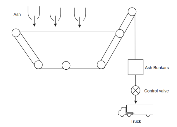
1) The hot ash released from the boilers is furnace is allowed to fall over the belt furnace conveyors. After cooling it through water.
2) This cold ash is transported through belt conveyors and falls in ash bunkers.
3) From ash bunkers ash is removed to dumping site with the help of truck.
Q10) Explain with diagram Electrostatic preceptor
A10)
Electrostatic preceptor:-
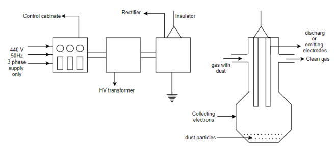
1) Dr FG Cottrell had introduced the electrostatic precipitator in 1905 and commercialized in 1937.
2) It consists offsets of electrodes insulated from each other one set is of electrical parallel plates called as collection electrodes.
3) The second set of electrodes consists of wires called as discharge for emitting electrodes.
4) The emitting electrodes posses negative high voltage (40-80Kv) from external DC source.
5) The dust laden gas is passed between two sets of oppositely charged electrodes and gas becomes ionised.
6) the positive and negative ions are formed positive ions travel to the negatively charged wire electrodes (discharged).
7) the electrons follow the electric field towards grounded electrons but their velocity decreases as they move away.
8) Gas molecules captures the low velocity electrons and becomes negative ions.
9) When these ions move to the collecting electrodes they collide with fly ash particles in the gas and give them negative charge.
10) the negatively charged fly ash particles are driven to the collecting plate by electrostatic force and separated from the gas.
11) The use of electrostatic precipitator is increasing day by day due to strict pollution.
Q11) write a note on Natural Draught system
A11)
Draught system:-
1) draught system is required to provide the sufficient amount of air for the proper combination of fuel to furnace grade.
2) Draught system is necessary for
i) To draw resultant gases from the system.
Ii) To discharge these gases from chimney to surrounding.
Iii) It is required to maintain the static pressure difference at grade which will cause the flow of air and gases take place.
Iv) This static pressure difference maintenance is called as boiler draught.
Natural draught:-
1) It is called as also chimney draught.
2) static pressure difference is developed into the chimney due to the difference in weight column of hot gases inside the chimney and weight of equal column of cold air outside chimney.
3) As density of cold air outside chimney is greater than the density of hot gases into the chimney, it follows that pressure just outside the level of chimney base would be greater than pressure inside chimney at its base.
4) this pressure difference is responsible for the flow of air from the surrounding to furnace grate.
5) The amount of draught produced by the chimney depends on
i) Chimney height
Ii) Temperature of flue gases
Iii) Temperature of surrounding cold ash.
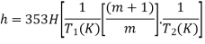
Where,
H=height of chimney
 =temperature of cold air
 temperature corresponding to 0°c 273 Kelvin
 =mean temperature of hot gases inside the chimney.
h=draught required in mm or water coil.
m=mass of air supplied per kg of fuel
m+1=mass of flue gases per kg of fuel.
Q12) write a note on Draught system, explain any one method.
A12)
Artificial draught:-
1) The draught required to natural power plant is sufficiently high (300 mm of water) and to meet the high drought requirement or the system, there should we use of artificial draught than natural draught.
It is also called as mechanical or forced draught.
2) Because of insufficient head and lock of flexibility the use of natural draught is limited to small capacity boilers only.
A) Forced draught:-
1) In forced draught system, blower (fan) is installed near the base of boiler and air is forced to pass through the furnace, economiser, air preheater and two stack.
2) This draught system is also known as positive draught system be cause the air is forced to flow to the system.
3) The function of chimney is to discharge the gases, high in the atmosphere to prevent contamination.
4) The chimney is not much significant for producing draught in this type. So height is chimney is a not very much.
Advantages of artificial draught:-
1) It reduces smoke.
2) Reduces necessary height of chimney.
3) It provides better control of combustion and increases plant and combustion efficiency.
4) It increases the evaporative capacity of boiler due to increase in quantity of fuel burner per metre square of grate area.
5) It allows to burn the low gradefuel also.
Disadvantages of artificial draught:-
1) Initial installation cost is low but the running cost is more due to blowers ( as per is required)
2) Maintenance is high due to wear and repair.
Q13) Explain with diagram Air preheater.
A13)
Air preheater
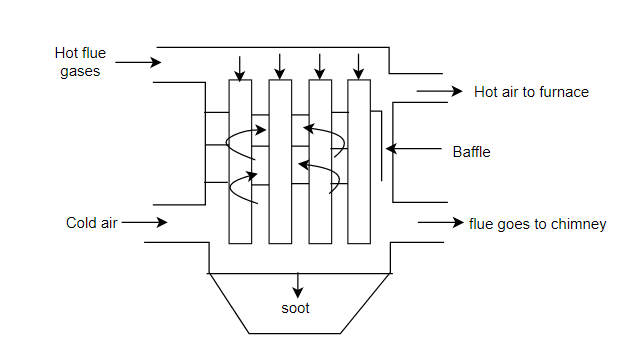
1) The device which uses waste heat of flue gases (from economiser) to heat that air to be supplied to boiler.
2) The flue gases are finally discharged to chimney from air preheater such device improves combustion efficiency of plant.
3) Hot flue gases passed through the tube and cold air is passed over the tubes.
4) Baffles are provided to increase the duration of contact for proper heat transfer between flue gases and cold air.
Q14) Write a note on Super heaters.
A14)
Super heaters:-
1) Super heater is a heat transfer device which consists of set of tubes.
2) The wet steam flows through these tubes and takes up heat from the flue gases passing over the steam pipe.
3) During this process wet steam is converted into superheated steam.
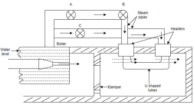
4) These tubes are made up of steel in U shape which are connected to two main headers.
5) Stop valve A is closed and B&C are open then wet steam flows from boiler to the right hand header through stop valve B
6) If superheated steam is not required stop valves B&C are closed and a is open then steam is directly taken out from stop valve A.
7) Superheating of steam can be controlled by controlling the quantity of flow of flue gases by operating the damper manually.
8) After superheating the steam in tubes, it flows into the left hand header and it is withdrawn from stop valve B.
9) the function of the super heater is to increase the temperature of steam above the saturation temperature.
10) It improves the overall thermal efficiency of plant.
Q15) Write a note on Economizer
A15)
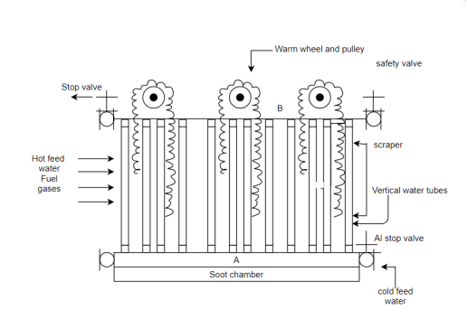
Economizer-
1) Economizer is there is a heat transfer device to heat the feed water by the heat of flue gases.
2) It consists of a large number of vertical tubes joint with the horizontal pipe at the bottom and B at the top.
3) Cold feed water is pumped into horizontal pipe a through stop valve.
4) hot flue gases from the boiler passes over this vertical tubes and these gases transfer heat to the cold water in the tubes.
5) Finally the feed water is heated and these hot feed water is again provided to boiler through valve of pipe B.
6) Safely valve is mounted to the other end of the pipe be to prevent the system from extra increasing high pressure.
7) Sootformation in the tube will affect the thermal conductivity and so heat transfer rate decreases and decrease the efficiency of economiser.
8) scrappers of two adjoining pipes are coupled by rod and change and this change process over the pulley.
9) Scrapers are provided to remove the deposit of soot from each vertical tubes these scrappers slide over the pipe by worm wheel and pulley arrangement at the rate of 0.75 metre per minute hence sootis removed and collected in soot chamber.
Advantages:-
1) Increases steam evaporation capacity of boiler.
2) Fuel saving
3) Decrease scale formation in water tube boilers.


