Unit - 3
Design of Staircase and Beams
Q1) What is dog legged staircase?
A1)
Dog legged staircase:
Dog legged staircase may be described because the sort of staircase that includes flights of stairs that run in contrary directions.
It is designed such that the flight of stairs keeps as much as 1/2 of step earlier than a flip of one hundred eighty levels and as a consequence keeps with inside the upward path.
This sort of staircase is likewise called canine-legged as it resembles the form of a canine’s leg with inside the sectional elevation.
The canine-legged staircase additionally guarantees much less expensive usage of the to be had area.
Hence, they may be significantly utilized in residential, public in addition to industrial buildings. It additionally gives stepped forward movement and compact area usage.
Q2) Explain actors and components of dog legged staircase.
A2)
Features of Dog legged Staircase
a. It looks as if a canine’s leg in sectional elevation.
b. It continually includes flights.
c. Height of every flight is identical to 1/2 of the ground height (h).
e. Number of risers in every flight is identical to the ratio of the peak of every flight and the rise.
Components of Dog Legged Staircase
The principal additives of the canine legged staircase may be indexed as follows:
a. Landing: The touchdown is the element or area among the collection of steps ordinarily to relaxation and permit and smooth extrude in path of the stairs.
b. Tread: Tread is the horizontal issue of the staircase wherein the foot is positioned in the course of ascending or descending thru the stairs.
c. Riser: The riser is the vertical issue of the staircase that lies among every tread with inside the staircase.
d. Step: Step discuss with the aggregate of a riser and tread.
e. Handrail: As the call itself implies, it gives guide to the fingers of the users.
f. Baluster: Baluster gives vertical guide to the handrail.
Q3) Explain requirement of good dog legged staircase.
A3)
Requirements of a Good Dog Legged Staircase
The simple requirement of the coolest and well-designed staircase is safety, ease and quickness. Some necessities of proper canine legged staircase are:
a. Location:
The canine legged staircase have to be placed such that it lets in smooth get right of entry to from all of the rooms of the constructing and gets tremendous mild and ventilation.
b. Length of Flight:
The flight of the staircase have to now no longer include risers much less than 3 and greater than sixteen.
c. Pitch of Stairs (Angle of staircase):
In widespread practice, the pitch of the canine legged staircase can variety among 15 levels to fifty five levels. However, a terrific staircase have to have the pitch starting from 25 levels to forty levels.
d. Landing:
For a well-deliberate staircase, the width of the touchdown have to now no longer be much less than the width of the stairs.
e. Proportions of Steps:
The risers and goings in every of the flights have to be identical to make certain the systematic association of steps and cushy ascend/descend.
Q4) What are the design steps of dog legged staircase?
A4)
Design steps of Dog Legged Staircase
The diverse steps concerned with inside the layout of the canine legged staircase may be indexed as follows:
a. Firstly, the peak of the upward push and duration required for every tread is assumed. The price of the peak of growing have to be taken among 150mm to 200mm even as the price of the duration required for every tread have to be taken among 250mm to 350mm relying upon the form of building.
b. Then, the width of the steps is calculated. Width of stairs = Total width of staircase/2
c. The peak of every flight is then determined. Height of every flight= Total peak/2
d. The quantity of risers in every flight is calculated. No. Of risers in every flight = Height of every flight / Height of riser in every flight
e. The quantity of treads is then calculated.
No. Of tread in every flight = No. Of risers in every flight – 1
f. Then, the overall duration required for treads is calculated as, Total duration required for treads = Length required for every tread x no. Of treads in every flight
g. The ultimate duration is then calculated with the aid of using subtracting the duration occupied with the aid of using the treads from the overall to be had duration.
Remaining duration = Total duration – Total duration occupied with the aid of using the treads
h. The duration of the touchdown is then assumed and subtracted from the above calculated ultimate duration to decide the distance for the passage.
Passage area = Remaining duration – Length of touchdown
In case, passage area isn't always required, the duration of the tread may be multiplied such that the complete duration is blanketed with the aid of using the treads and landings.
Q5) Calculate the dimensions and design a dog-legged staircase for a residential building with the following details.
The building has a vertical distance between the floors of 3.8 meter. The given dimension of the staircase is 3.5 x 5 m.
A5)
Step 1: Assuming the riser and tread dimensions.
Let, the height of riser is 150mm and the length required for each tread be 250mm respectively.
Step 2: Calculation of the width of the stairs.
Let, the number of flights is 2. Now,
Width of stairs = 3.5 / 2 = 1.75 m = 1750 mm
Step 3: Calculation of height of each flight.
Height of each flight = 3.8 / 2 = 1.9 m = 1900 mm
Step 4: Calculation of no. Of the riser in each flight
No. Of risers in each flight= Height of each flight / Height of riser in each flight
= 1900 / 150 = 12.67 = 13 risers
Step 5: Calculation of no. Of tread in each flight
No. Of tread in each floor = No. Of risers in each flight – 1
= 13 – 1 = 12 treads
Step 6: Calculation of length required for treads
Total length required for treads = 12 x 250 mm = 3000 mm = 3 m
Step 7: Calculation of Remaining Length
Remaining Length = 5 m – 3 m = 2 m
Step 8: Calculation of Space for Passage
Space for Passage = 2 m – 1.5 m
(Assuming width of landing = 1.5m)
= 2 m – 1.5 m = 0.5 m
Q6) Give advantages and disadvantages of dog legged staircase.
A6)
Advantages of Dog Legged Staircase
a. Efficient Space Utilization: The layout of the canine legged staircase gives most cost-efficient and green use of the to be had space.
b. Simple and Economical: It has an easy layout and is most cost-efficient.
c. Improved Privacy: It gives substantial privateers among the floors. The layout is such that one ground can't be seen from any other ground.
Disadvantages of Dog Legged Staircase
a. Difficult Construction: This kind of staircase is noticeably hard to construct.
b. Positioning of Handrails: The positioning of handrails is relatively complex.
Q7) What is open well staircase?
A7)
Open Well staircase:
A stair flight is a run of consecutive stair steps. A staircase may be composed of numerous stair flights that are separated via way of means of landings.
A touchdown is a horizontal detail that permits the relationship among or extra flights.
It gives a resting vicinity and permits the get right of entry to the special zones of the stairway.
There are ground landings (that deliver get right of entry to the special regions of the ground) and intermediate landings (that join the flights among them).
The vertical component among every tread at the stair is known as rise/riser. The intensity of the tread is known as run or going. Staircase indoors design.
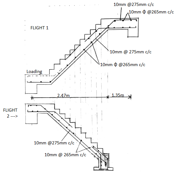
Q8) Design open well staircase. Draw the plan showing flight details, mid-landings etc. Draw reinforcement details in a flight. Grade of concrete is M20 and steel Fe415.
A8)
Step 1:
Floor to floor height = 3.1m (Open well)
M20 Fe415
Fck = 20N/mm2
Fy = 415N/mm2
M − 0.138 fck bd2
Step 2: Preliminary Dimensions
Floor to floor height = 3.1m
Height of each fright = 3.12 = 1.55m
But in this case we need to design open well staircase
∴ Assume Riser = 155mm
Total Riser = 3100
Since in open well staircase there are 3 flights
∴ Total tread = 20 - 3 = 17
∴ Provide 7 tread in 1st flight, 3 tread in 2nd flight, 7 tread in 3rd flight
Assume tread=250mm
Assume width of the landing to be 1m (effective)

Step 3: Effective span and depth
Less for Ist and IIIrd flight
Less = 1.75 + 1 = 2.75 m
Less of IInd flight
Less = 1 + 1 0.75 = 2.75 m
d=less Bv × mfd = assume % of steel = 0.4%, mf = 1.15, Bv = 20
275020 × 1.15 = 119.6
∴ Provide d = 130 mm
Effective cover = 25 mm
Doverall=155mm
Step 4: Load calculations
Ongoing portion
1) Self wt. Of slab
2) Self wt of step
3)LL= 3KN/m = 25DR2 + T2 −−−−−−− √T = 25 × 0.155 × 0.1552 + 0.252
Self wt. Of slab = 25DR2 + T2T = 25 × 0.155 × 0.1552 + 0.2520 = 4.56 KN/m2
Self wt of step = 25R2 = 25×0.1552 =1.94KN/m3
Total load = 10.5 KN/m
Ultimate load = 16.75 KN/m
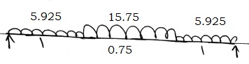
ON LOADING PORTION
1) Self wt. Of slab = 25×D25×D = 3.9 KN/m
2) LL = 3 KN/m FF = 1 KN/m
Total = 7.9 KN/m
Ultimate = 11.85 KN/m
As per clause 33.2 page 63 on half load has to be considered in open well staircase
Step 5: Pending Moment
For Ist and IIIrd flight

RA+RB = (5.925×1) + (15.75×1.75) = 33.5KN
RA+RB = (5.925×1) + (15.75×1.75) = 33.5KN
Moment of B
M@B = 0 = [5.925×1× (0.5+1.75)] +15.75×1.7522−RA×2.75[5.925×1× (0.5+1.75)] + 15.75×1.7522 − RA×2.75
RA= 3.62KN
RB=19.88KN
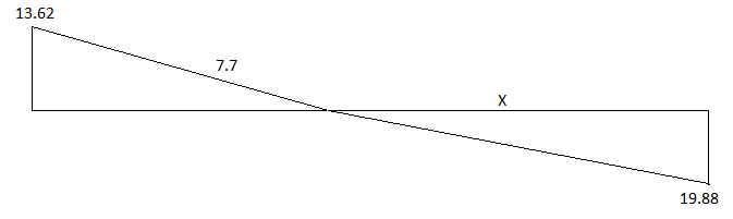
x=1.26mx=1.26m
Mmax = (19.88×1.26) − (15.75×1.2622) =12.55KN/m ==
For IInd flight
RA+RB = 23.66
RA = RB = 11.83
Max at mid span = (11.83×1.375) − [5.925× (0.5+0752)] − (15.75×0.37522) (11.83×1.375) − [5.925× (0.5+0752)] − (15.75×0.37522)
Mmax = 10 KNm
Step 6: Check for depth
d= M 0.138 fck Bv = 67.43mm < d provided
∴ Safed=M0.138 fck
b=67.43mm < d provided
∴ Safe
Step 7: Ast calculation
Since moment is almost same provide Ast for Max moment
Ast = (0.5×204.5) [1−1−4.6×12.55×10620×1000×1302
Ast = 280mm2 \
∴∴ Provide #10mm @ 275mm c/c
Distribution Steel
Astmin = 0.12100bD = 186mm2
Provide #10mm @ 265 mm c/c
Step 8: Check for deflection
% of Steel provided = 285.61000×130×100 = 0.22285.61000×130×100 = 0.22
∴ Safe
Step 9: Check for Shear
Vmax=15.75×2.752=21.66KN
VUC = τc bd K = 1.15×0.28×1000×130 = 1.86KN
∴ Safe
Step 10: Check for development length
Ld < 1.3M1V + LD Ld < 1.3M1V+LD
Ld = ϕ fy 0.874τbd = 10×415×0.874×1.6×1.2 = 470.12mmLd
M1= 12.552=6.275KNm
V=4.66KN
∴1.3×6.275×1064.66×103 = 476mm
∴ Safe
Q9) Explain design of simply supported beam for flexure, shear, bond and torsion
A9)
- Identify the masses
- The beams convey masses because of self-weight, slabs, stay masses and lifeless masses due different structural additives or equipment’s.
- These are elevated through an appropriate element after which carried out at the beams as dispensed masses (udl, triangular etc.) except the factored focused masses, if any.
- Draw the BMD and SFD Using the masses and genuinely supported condition, we draw the BMD and SFD to realize the significance and role of most bending moment (M) and shear force (V) at the beam. Cross phase location and metal required
- We determine upon the go phase location b*D (say, .25 * .four m2, as a popular rule for four m span, the intensity of four hundred mm need to suffice) as properly the grade of concrete and metal to be used.
- We can calculate the powerful intensity d = D-Cover to beam-Half the dia of reinforcement. Now we can have the ratio M/b (d^2).
- Using Table 1 to six of SP: 16, we get the reinforcement % for singly strengthened beam and Table forty five to fifty six offers the reinforcement % for doubly strengthened beam.
- From which we can have Total location of metal required = (% obtained )* b* d/ 100 Dividing the Total location of metal required through the location of 1 bar of metal of appropriate dia offers the no. Of bars required.
- The overall location of metal required ought to fulfill the the minimal location of anxiety reinforcement as in line with 26.5.1.1 of IS: 456.
- Shear Reinforcement required Nominal shear pressure is calculated as, t= V/b*d
- Design Shear Strength of Concrete, tic : Table sixty one of SP:16 (Use the % of reinforcement supplied and now no longer the % required.)
- Maximum Shear Stress tcmax: Table J of SP: 16 If t >tc, shear reinforcement will be supplied for shear force, V’ = (V-tc*b*d) (If t >tc max additionally, then beam is to be redesigned with a one of a kind c/s.)
- Spacing of stirrups s = (0.87*fy* overall go sectional location of the vertical legs of the stirrups* d)/ V’ [In case we are using Vertical stirrups only.]
- This fee shall now no longer exceed 0.seventy five d Detailing of reinforcement
- We offer a nominal reinforcement with inside the compression quarter additionally given through the clause 26.5.1.1 of IS: 456
Q10) Explain design of cantilever beams.
A10)
A cantilever beam is an inflexible structural detail supported at one give up and loose on the other, as proven in Figure-1. The cantilever beam may be both product of concrete or metal whose one give up is solid or anchored to a vertical guide.
It is a horizontal beam shape whose loose give up is uncovered to vertical hundreds. In a building, a cantilever is built as an extension of a non-stop beam, and in bridges, its miles a section of a cantilever girder. It may be built both solid-in-situ or via way of means of segmental production via way of means of pre-stressing methods.
Cantilever production permits overhanging systems without extra helps and bracing. This structural detail is extensively used with inside the production of bridges, towers, and buildings, and might upload a completely unique splendor to the shape.
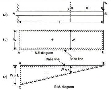
Q11) Explain Shear Force (SF) and Bending Moment (BM) Diagram of Cantilever Beam
A11)
The shear pressure at any phase of a cantilever beam is the sum of hundreds among the phase and the loose give up.
The bending second at a given phase of a cantilever beam is the sum of moments approximately the phase of all of the hundreds appearing among the phase and the loose give up.
Consider a cantilever beam AB of length 'l' subjected to some extent load 'W' on the give up B. A phase X-X at a distance 'x' from the loose give up B is placed.
Then the shear pressure at phase X-X is Rx, that's identical to W and the bending second approximately the phase X-X is Mx, that's identical to W.x.
The shear pressure on the constant guide A is decided via way of means of maintaining the phase at A, which offers the shear pressure Ra=W; and second Ma = W.l. Primarily based totally on which the shear pressure and bending second diagram are developed.
The bending second of a cantilever beam is most on the constant give up and reduces to 0 on the loose give up.
The bending and shear pressure diagram is decided for all viable load combos to lay out a cantilever beam for a shape.
The load implemented at the beam is a mixture of lifeless load and stay hundreds as according to the layout standards.
The most span of a cantilever beam is typically depending on the subsequent factors:
The intensity of the cantilever
The magnitude, type, and place of the load
The excellent and form of fabric used
Usually, for small cantilever beams, the span is constrained to two to a few m.
But the span may be elevated both through growing the intensity or the use of a metallic and pre-harassed structural unit.
The span may be built lengthy, for the reason that the shape can counteract the moments generated through the cantilever and effectively switch it to the ground.
A certain evaluation and layout of the shape can assist examine the opportunity of lengthy spanned cantilever beams.
The cantilever beam should be nicely constant to the wall or assist to lessen the impact of overturning.
Q12) Give application, advantages and disadvantages of cantilever beam.
A12)
Applications of Cantilever Beam in Construction
- Cantilever beam systems are used with inside the following applications:
- Construction of cantilever beams and balconies
- Temporary cantilever assist systems
- Freestanding radio towers without guy-wires
- Construction of cantilever beam for pergolas
- Lintel creation in buildings
Advantages and Disadvantages of Cantilever Beams
The critical benefits of cantilever beams are:
Cantilever beams do now no longer require help on the alternative side.
The bad bending second created in cantilever beams allows to counteract the tremendous bending moments created.
Cantilever beams may be effortlessly constructed.
The hazards of cantilever beams are:
Cantilever beams are subjected to massive deflections.
Cantilever beams are subjected to large moments.
A robust constant help or a backspin is essential to preserve the shape stable.
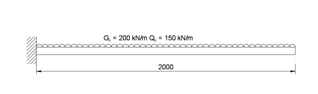
Q13) Design a suitable UB section in S355 steel. Assume the beam is fully laterally restrained. Assume self-weight of beam is included in the permanent action below.
A13)
Design Bending Moment and Shear Force
Design action FED = (γGgk+γQqk) x span
= (1.35 x 200 + 1.5 x 150) x 2 = 990 kN
Design Bending moment, (MED) = FEDl2=990x22=990kNm
Design Shear force, VED
VED = FED = 990 kN
Note – bending moment for a cantilever beam is wL2 /2.
Section Selection
The cantilever beam is relatively short and will be subject to high moment and shear. A section needs to be chosen to resist these forces. This can be chosen through calculating the plastic modulus.
Wpl,y ≥ Mpl,Rd γMO/fy = 990 x 106 x 1.0/355 = 2789 x 103 mm2 = 2789 cm3
The shear area of the section, Av, must exceed the following to satisfy shear:
Av ≥ Vpl,RdγMO/(fy/√3) = 990 x 103 x 1.00/(355/√3) = 4830 mm2
Looking at Tata Steel blue book, we can choose the Universal Beam with a greater plastic modulus. Hence, try UB 610 x 210 x 113.
Check Strength Classification
Part subject to compression:
ϵ = (235/fy)0.5 = (235/355)0.5 = 0.81
c/tf =95.85/17.3=5.54<9ε=9×0.81=7.29
C = (b-tw – 2r)/2 = 228.2 – 11.1 – 2 x 12.7)/2 = 191.7/2 =95.85 mm
Part subject to bending:
c/t_w =547.6/11.1=49.3<72ε=72×0.81=58.32
Therefore, from Table 5.2 of Eurocode 3, section UB 610x229x113 is class 1.
Resistance of Cross-Section
Bending
Since the beam section belongs to class 1, the plastic moment of resistance can be calculated from the equation below:
Mpl,Rd = Wpl,yfy/ γMO = 3280 x 103 x 355 / 1.0
= 1164.4 x 102 Nmm > 1164.4 kNm > 990 kNm OKAY in bending (Utilisation ratio of 0.85)
Shear
Design shear force is defined as VED, is
VED = 990 kN
For class 1 section design plastic shear resistance, Vpl,Rd is given in the equation below:
Vpl,Rd =Av(fy/√3)/γMO
Where Av = A-2btf + (tw + 2r)tf ≥ηhwtw = 1.0 x 547.6 x 11.1 = 6078.4mm2
Av = 144 x 102 – 2 x 228.2 x 17.3 + (11.1+2 x 12.7)17.3 = 7135.7 mm2 …. OKAY
Hence, Vpl,Rd = 7135.7 (355/√3)/1.0
= 1462 x 103 N = 1462 kN > 990 kN OKAY (Utilisation = 0.68)
Bending and Shear
Since VED = 990 kN > 0.5 Vpl,Rd = 731 kN
Therefore, this section is subject to ‘high shear load’ and the design resistant moment of the section (about major axis) should be reduced to My,V,Rd.
My,V,Rd = [(Wpl,y - Aw2/4tW)fy]/Ym0
= 3280×103–0.13×6078.362/(4×11.1))3551.0
= 1125 x 106 Nmm = 1125 kNm > 990 kNm
Where ρ=(2VED/Vpl,Rd – 1)2 = (2 x 990/1462 – 1)2 = 0.13
Aw = hwtw = 547.6 x 11.1 = 6078.36 mm2
Therefore, UB 610 x 229 x 113 is satisfactory in bending and shear.
It should be noted that the design of cantilever beams with longer lengths require deeper sections to mitigate against deflection, twisting and warping (i.e. bending moment and shear is not a major factor).


