Unit - 2
Design of Compression Members and Columns
Q1) Explain Buckling classification?
A1)
Following 3 classification of buckling:
1. Flexural buckling
2. Local buckling
3. Torsional buckling
1. Flexural buckling:
Flexural Buckling (additionally known as Euler Buckling) is the number one kind of buckling members are subjected to bending or flexure when they grow to be unstable
2. Local Buckling
This takes place while some component or elements of x-phase of a column are so skinny that they buckle domestically in compression earlier than different modes of buckling can occur
3. Torsional Buckling
These columns fail by twisting (torsion) or blended impact of tensional and flexural buckling
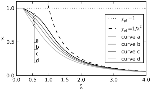
Q2) What is buckling curves?
A2)
Buckling curves constitute the impact of residual stresses and geometric imperfections at the buckling failure conduct of the member.
As may be visible in fig., those impacts are maximum suggested (for intermediate values of the slenderness among 0.5 and 1.5).
Q3) Explain Classification of cross Section?
A3)
Classification of cross section
Cross section | Limit | Buckling about axis | Buckling class |
Rolled I section | h/bf>1.2:tf<40mm 40<mm<tf<100mm | z-z y-y z-z y-y | A B B C |
Welded I section | Tf<40mm Tf>40mm | z-z y-y z-z y-y | b c c d |
Hollow section | Hot rolled | Any | A |
| Cold rolled | Any | B |
Welded box section | Generally (expected as below) | Any | B |
| Thick welds and b/tf<30 h/tf<30 |
z-z y-y |
c c |
Channel, angle, T and Solid sections |
| Any | C |
Built up member |
| Any | C |
Q4) What is effective length for compression members and columns?
A4)
Buckling of columns are largely depends upon support conditions. In each case there is a portion of the length of the compression member bends from the points of contra flexure.
The effective length KL of a compression member is the distance between these points. Therefore, it should be derived from the actual length and end / support conditions. Tables 1 and 2 the effective length (kl) of columns and struts respectively for various end conditions.
Boundary condition | Schematic representation | Effective length | |||
At one end | At the other end | ||||
Translation | Rotation | Translation | Rotation | ||
Restrained | Restrained | Free | Free |  | 2.0 L |
Free | Restrained | Restrained | Free | 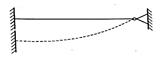 | 2.0 L |
Restrained | Free | Restrained | Free | 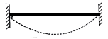 | 1.0L |
Restrained | Restrained | Free | Restrained | 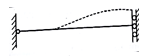 | 1.2 L |
Restrained | Restrained | Restrained | Free | 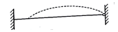 | 0.8L |
Restrained | Restrained | Restrained | Restrained | 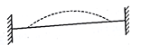 | 0.65L |
Q5) Check the adequacy of an ISA 70 x 70 x 6 @ 6.3 kg/m to factored axial compressive load of 160kn. Two angles are connected on either side of 8 mm thick gusset plate by 4 numbers of M20 black bolts of 4.6 grades. The effective length of strut is 2.3 m
A5)
1) Properties of 2 ISA 70 x70x6 @ 6.3 kg/m
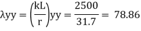
A= 1260 mm^2, rzz= 21.4 mm, ryy= 31.7 mm
2) Slenderness ratio
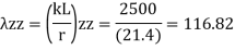
3) Buckling class
Using table 10, IS 800-2007
Buckling class of an angle= C
4) Design compressive stress (Fcd)
Kl/r | Fy=250 |
110 | 94.6 |
116.82 | Fcd |
120 | 83.7 |
By interpolation
Fcd = 87.16 MPa
5) Design compressive strength
Pd= Ae x Fcd = 1260 X 87.16 = 109.82 kN
Hence section is adequate.
Q6) Determine the design strength of a column section ISLB 500 @ 75 kg/m with the effective length of the column as 5m. Assume buckling axis as z-z axis and yield stress of steel fy = 250 Mpa
A6)
Properties of section – ISLB 500 @ 75 kg/m
Area= 9559 mm^2, rzz= 201 mm
Effective length KL= 5000 mm
1) Slenderness ratio
2) Buckling compressive stress (fcd)
From table 9(a) IS 800-2007
KL/r | Fcd |
20 | 226 |
24.87 | ? |
30 | 220 |
By interpolation
Fcd = 223.07 MPa
3) Design compressive strength (Pd)
Pd= Ae.fcd= 9550 x 223.07 = 2130.3 kN
Pd= 2130.3 kN
Q7) Explain Design of compression member of trusses using single and double angle section and design of connections?
A7)
Strength of compression member
The power of a compression member is described as its secure load sporting potential. The power of a centrally loaded immediately metal column relies upon at the powerful cross-sectional place, radius of gyration (viz., form of the cross-phase), the powerful duration, the importance and distribution of residual stresses, annealing, out of straightness and bloodless straightening.
The powerful cross-sectional place and the slenderness ratio of the compression contributors are the primary features, which have an effect on its power.
In case, the allowable stress is thought to differ parabolic ally with the slenderness ratio, it could be proved that the performance of a form of a compression member is associated with A/r2.
The performance of a form is described because the ratio of the allowable load for a given slenderness ratio to that for slenderness ratio identical to zero. The secure load sporting potential of compression member of recognized sectional place can be decided as follows:
Step1]
From the actual duration of the compression member and the guide situations of the member, that are recognized, the powerful duration of the member is computed.
Step 2]
From the radius of gyration approximately diverse axes of the phase given in phase tables, the minimum radius of gyration (rmin) is taken. rmin for a constructed-up phase is calculated.
Step 3]
The most slenderness ratio (l/ rmin) is decided for the compression member.
Step 4]
The allowable running stress (σac) within side the route of compression is found similar to the most slenderness ratio of the column from IS:800-1984.
Step 5]
The powerful sectional place (A) of the member is stated from structural metal phase tables. For the constructed-up contributors it could be calculated.
Step 6]
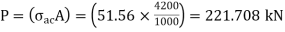
The secure load sporting potential of the member is decided as P= (σac. A), where P=secure load
Q8) A single angle discontinuous strut ISA 150 mm x 150 mm x 12 mm (ISA 150 150, @0.272 kN/m) with single riveted connection is 3.5 m long. Calculate safe load carrying capacity of the section.
A8)
Step 1: Properties of angle section
ISA 150 mm x 150 mm x 12 mm (ISA 150 150, @0.272 kN/m) is used as discontinuous strut. From the steel tables, the geometrical properties of the section are as follows:
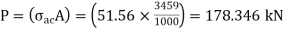
Sectional area A = 3459 mm2
Radius of gyration rxx= ryy=149.3 mm
Radius of gyration ruu= 58.3 mm, rvv=29.3 mm
Step 2: Slenderness ratio,
Minimum radius of gyration rmin= 29.3 mm
Effective length of strut l= 3.5 m
Slenderness ratio of the strut
Step 3: Safe load
From IS:800-1984 for l/r=119.5 and the steel having yield stress, fy=260 N/mm2, allowable working stress in compression σac =64.45 N/mm2 (MPa)
For single angle discontinuous strut with single riveted connection, allowable working stress
0.80 σac = (0.80 x 64.45) = 51.56 N/mm2.
The safe load carrying capacity
Q9) In case in Example, a discontinuous strut 150 x 150 x 15 angle section is used, calculate the safe load carrying capacity of the section.
A9)
Step 1: Properties of angle section
Angle section 150 mm x 150 mm x 15 mm is used as discontinuous strut. From the steel tables, the geometrical properties of the section are as follows:
Sectional area A = 4300 mm2
Radius of gyration rxx= ryy=45.7 mm
Radius of gyration ruu= 57.6 mm, rvv=29.3 mm
Step 2: Slenderness ratio,
Minimum radius of gyration rmin= 29.3 mm
Effective length of strut l= 3.5 m
Slenderness ratio of the strut
Step 3: Safe load
From IS: 800-1984 for l/r=119.5 and the steel having yield stress, fy=260 N/mm2, allowable working stress in compression σac =64.45 N/mm2 (MPa)
For single angle discontinuous strut with single riveted connection, allowable working stress
0.80 σac = (0.80 x 64.45) = 51.56 N/mm2.
The safe load carrying capacity
Q10) In Example, if single angle discontinuous strut is connected with more than two rivets in line along the angle at each end, calculate the safe load carrying capacity of the section.
A10)
Step 1: Properties of angle section
Discontinuous strut ISA 150 mm x 150 mm x 12 mm (ISA 150 150, @0.272 kN/m) is used with double riveted connections. From the steel tables, the geometrical properties of the section are as follows:
Sectional area A = 3459 mm2
Radius of gyration rxx= ryy=149.3 mm
Radius of gyration ruu= 58.3 mm, rvv=29.3 mm
Length of strut between center to center of intersection L=3.50 m
Step 2: Slenderness ratio,
Minimum radius of gyration rmin= 29.3 mm
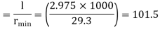
Effective length of discontinuous strut double riveted 0.85 x L= 0.85 x 3.5 = 2.975 m
Slenderness ratio of the strut
Step 3: Safe load
From IS:800-1984 for l/r=101.5 and the steel having yield stress, fy=260 N/mm2, allowable working stress in compression σac =71.65 N/mm2 (MPa)
Allowable working stress for discontinuous strut double riveted is not reduced.
The safe load carrying capacity 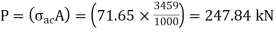
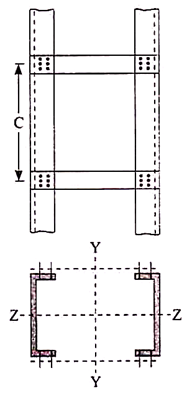
Q11) A double angle discontinuous strut ISA 125 mm x 95 mm x 10 mm (ISA 125 95, @0.165 kN/m) long legs back-to-back is connected to both the sides of a gusset plate 10 mm thick with 2 rivets. The length of strut between center to center of intersections is 4 m. Determine the safe load carrying capacity of the section.
A11)
Step 1: Properties of angle section
The double angle discontinuous strut 2 ISA 125 mm x 95 mm x 10 mm (ISA 125 95, @0.165 kN/m) is shown in Fig. 11.4. Assume the tacking rivets are used along the length. From the steel tables, the geometrical properties of (two angle back-to-back) the sections are as follows:
Sectional area A = 4204 mm2
Radius of gyration rxx= 39.4 mm
Angles are 10 mm apart
Radius of gyration ryy= 40.1 mm
Length of strut between center to center of intersection L=4 m
Step 2: Slenderness ratio,
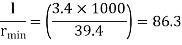
Minimum radius of gyration rmin= 39.4 mm
Effective length of discontinuous strut 0.85 x L= 0.85 x 4.0 = 3.40 m
Slenderness ratio of the strut
Step 3: Safe load
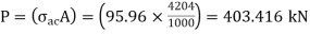
From IS:800-1984 for l/r=86.3 and the steel having yield stress, fy=260 N/mm2, allowable working stress in compression σac =95.96 N/mm2 (MPa)
The safe load carrying capacity
Q12) Explain Design of axially loaded column using rolled steel section?
A12)
To design a compression member, length, end conditions and load it has to support are required.
The designer is supposed to select a section which provides a large radius of gyration without providing more area and in which the design compressive strength (P) just exceeds the factored compressive load.
To find compressive strength, the area of cross section and radius of gyration must be known. So cut of these two unknowns, one unknown should be assumed and compute other. Then section is checked
Step (1): The design compressive stress (F) is to be assumed.
There is no proper estimation of slenderness ratio for any length and support condition, therefore for a trial, range of F for slenderness ratio given below.
(a) For Angle strut: The slenderness ratio varies from 110 to 130. Hence assume F in between 80 to 110
(b) For rolled beam sections: The slenderness ratio varies from 70 to 100. Hence assume F in between 110 to 180 MPa.
Notes: For a column with heavy factored load and large lengthy height, required large radius of gyration. Therefore, built up sections are required to the selected for design
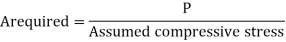
Step (2): Selection of section:
A required= P/fcd
Step (3): Classification of section
Step (4): Knowing and conditions and determine effective length (kl). Also find out slenderness ratio.
Step (5): Determine buckling class using table 10 of IS 800-2007
Step (6): Determine design compressive stress (f)
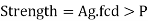
Step (7): Determine design compressive strength P
Using Pd= Ae.fcd>P Safe
Step (8): Revise the section if P, <P (factored load) till it will safe.
Q13) What is Design of built-up column, lacing and battening and its connections?
A13)
Built-up sections are preferred instead of rolled steel sections for a column in industrial buildings because.
(1) Span and height of industrial buildings are large, so the load on the columns are enough large such that available rolled steel sections are unable to sustain loads.
(2) Also, built up sections are designed such that the radius of gyration about two principal axes is same.
(3) Lacing and battening in built up column restrain lateral buckling of column.
(4) Finally, design strength of built-up sections more than available rolled steel sections.
Lacing and battening are used in built up section of column is large for toll purpose. (1) To restrain lateral buckling of column section as the height of built-up column is large.
(2) The sections of built-up column to act a single section.
Design of Laced Column
Procedure
(A) Design of Column
1) The design compressive stress is assumed. It is difficult for an excellent assumption of slenderness ratio or design compressive stress. Is in the range of 125 to 185 MPa assumed for f, = 250 MPa of steel.
2) Selection of cross section:
Where,
A = Cross-sectional area in mm²
P= Factored axial compressive force.
A suitable section comprising of two channels of four channels or four angles or two I sections with or without extra plates as required is selected from steel table.
(3) Effective length (kL) depends upon end /support conditions is determined and the slenderness ratio is determined.
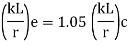
The effective slenderness of laced column should be taken as in order to account for  ratio 1.05 times
  deformation effect.
(4) For the estimated value of the slenderness ratio the design compressive stress (f) is computed from Table 9(a), (b), (c) and (d).
5) The design compressive strength is computed. It should be more than the factored load over the section.
(6) The sections are so placed that the radius of gyration of section about the axis perpendicular to the plane of lacing is not less than the radius of gyration about the axis in the plane of lacing. This is achieved by making ryy>rzz
(B) Design of Lacing Bar
(1) Angle of inclination of lacing bar with the longitudinal axis of the component member should be kept between 40"-70". As an initial trial value 0 may be assumed to be 45° and the spacing of lacing bars a, r, is calculated.
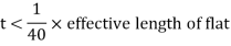
(2) The maximum spacing of lacing bars a, should be such that minimum slenderness ratio of the component member a/r, is not greater than 50 or 0.7 times the slenderness ratio of the member as a whole,
Where, a, = is the length of component member.
Ryy=radius of gyration @ y-y axis.
(3) The lacing for compression members should be proportioned to resist a total transverse shear v₁= 2.5% of axial load. This shear v, is divided equally in all parallel planes N in which there is shear resisting elements, such as lacing or continuous plates. Hence v/N is the transverse force to which the lacing is subjected N=2 for two channels laced on both faces.
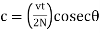
The compressive force in the lacing bar
 For single lacing system
 For double lacing system
The section of the lacing flat initially assumed and then check for safety.
(1) Diameter of bolt or rivet assumed (d)
(ii) Width = b > 3d
(iii) Thickness = t
For single lacing
For double lacing
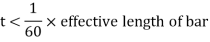
(6) rmin of lacing flat 
(7) 
Where, KL = Distance between inner end bolts (for single lacing)
= 0.7 x L for double lacing
= 0.7 x inner length of plate weld.
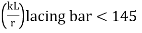
(8) Design compressive stress (f) is determined and also design compressive strength of lacing plate is calculated which should be more than 'c'.
(9) Determine tensile strength of lacing plate using yielding of gross cross-section and rupture at net cross section.
(10) Design the connection (bolted or welded)
(11) Detailing.
Battening and its connections
Compression members composed of two main components battened should preferably have the individual members of the same cross-section and symmetrically disposed about their major axis.
Where practicable, the compression members should have a radius of gyration about the axis perpendicular to the plane of the batten not less than the radius of gyration about the axis parallel to the plane of the batten.
The battens should be placed opposite to each end of the member and at points where the member is stayed in its length and as far as practicable, be spaced and proportioned uniformly throughout.
The number of battens shall be such that the member is divided into not less than three bays within its actual length from center to center of end connections.
The effective slenderness ratio (KL/r) c of battened columns, shall be taken as 1.1-time (KL/r) o, the maximum actual slenderness ratio of the column, to account for shear deformation effects.
Design of Battens:
Battens shall be designed to carry the bending moments and shear forces arising from transverse shear force Vt equal to 2.5 per cent of the total axial force in the whole compression member, at any point in the length of the member divided equally between parallel planes of the battens.
Battened member divided equally between parallel planes of the battens.
Battened member carrying calculated bending moment due to eccentricity of axial loading, calculated end moments or lateral loads parallel to the plane of battens, shall be designed to carry actual shear in addition to the above shear.
The main members shall also be checked for the same shear force and bending moments as for the battens.
Battens shall be of plates, angles, channels or I-sections and at their ends shall be riveted, bolted or welded to the main components so as to resist simultaneously a shear Vb = (V1C)/N5 along the column axis and a moment M = (V1C)/2N at each connection.
Where,
V1 = Transverse shear force as defined above
C = Distance between center to center of battens, longitudinally
N = Number of parallel planes of battens, and
S = Minimum transverse distance between the centroid of the rivet/bolt group/welding connecting the batten to the main member.
Tie Plates:
Tie plates are members provided at the end of battened and laced members, and shall be designed by the same method as battens. In no case shall a tie plate and its fastening be incapable of carrying the forces for which the lacing or batten has been designed.
Size:
When plates are used for battens, the end battens and those at points where the member is stayed in its length shall have an effective depth, longitudinally, not less than the perpendicular distance between the centroids of the main members.
The intermediate battens shall have an effective depth of not less than three quarters of this distance, but in no case shall the effective depth of any batten be less than twice the width of one member in the plane of the battens.
The effective depth of a batten shall be taken as the longitudinal distance between outermost bolts, rivets or welds at the ends. The thickness of batten or the tie plates shall be not less than one-fiftieth of the distance between the innermost connecting lines of rivets, bolts or welds, perpendicular to the main member.
The requirement of bolt size and thickness of batten specified above does not apply when angles, channels or I-sections are used for battens with their legs or flanges perpendicular to the main member. However, it should be ensured that the ends of the compression members are tied to achieve rigidity.
Spacing of Battens:
In battened compression members where the individual members are not specifically checked for shear stress and bending moments, the spacing of battens, center to center of its end fastenings shall be such that the slenderness ratio (KL/r) of any component over that distance shall be neither greater than 50 nor greater than 0.7 times the slenderness ratio of the member as a whole about its Z-Z (axis parallel to the battens).
Q14) Explain Design compressive stress?
A14)
Compressive strength or compression strength is the capability of a fabric or shape to resist hundreds tending to lessen size (instead of tensile strength which withstands hundreds tending to elongate). Compressive strength is a key cost for layout of structures.
Compressive strength or compression strength is the capability of a fabric or shape to resist hundreds tending to lessen size (instead of tensile strength which withstands hundreds tending to elongate). In different words, compressive electricity resists compression (being driven together), while tensile strength resists tension (being pulled apart).
In the observe of strength of substances, tensile strength, compressive strength, and shear strength may be analyzed independently. Some substances fracture at their compressive strength restrict; others deform irreversibly, so a given quantity of deformation can be taken into consideration because the restrict for compressive load. Compressive strength is a key price for layout of structures.
Compressive strength is regularly measured on a regularly occurring trying out machine. Measurements of compressive strength are suffering from the unique check approach and situations of measurement. Compressive strengths are typically stated in courting to a selected technical standard
Procedure
1) Properties of 2 ISA 70 x70x6 @ 6.3 kg/m
2) Slenderness ratio

3) Buckling class
Using table 10, IS 800-2007
Buckling class of an angle= C
4) Design compressive stress (Fcd)
5) Design compressive strength
Pd= Ae x Fcd


