Unit - 4
IIR Filter Design & Realization
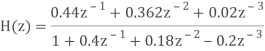
Q1) For the following LTI system H(z)= . Realise the cascade form IIR filter.
A1) H(z)=
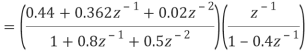
The above function can be simplified as
H(z)=
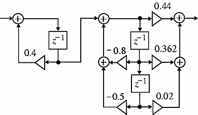
Hence, using the above structure and placing the values of 
 …. And similarly,

Fig: Cascade Form realisation of IIR Filter
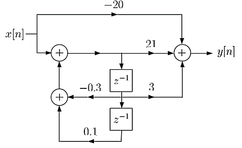
Q2) Draw block diagram for the function using parallel form H(z)=
A2) H(z)=
Writing above transfer function in standard form for parallel realisation we get
H(z)=-20+
The structure is shown below

Q3) Compare IIR and FIR filters?
A3)
Sr. No | IIR system | FIR system |
1. | IIR stands for infinite impulse response systems | FIR stands for finite impulse response systems |
2. | IIR filters are less powerful that FIR filters, & require less processing power and less work to set up the filters | FIR filters are more powerful than IIR filters, but also require more processing power and more work to set up the filters |
3. | They are easier to change “on the fly”. | They are also less easy to change “on the fly” as you can by tweaking (say) the frequency setting of a parametric (IIR) filter |
4. | These are less flexible. | Their greater power means more flexibility and ability to finely adjust the response of your active loudspeaker. |
5. | It cannot implement linear-phase filtering. | It can implement linear-phase filtering. |
6. | It cannot be used to correct frequency-response errors in a loudspeaker | It can be used to correct frequency- response errors in a loudspeaker to a finer degree of precision than using IIRs. |
Q4) Realise Direct form II and cascade form realizations of

A4) 

Direct form II
Cascade form
Q5) Realise the parallel form for 
A5) A partial fraction expansion of


The corresponding parallel form I realization is shown below

Q6) Draw block diagram for the function using parallel form H(z)=
A6)
H(z)=
Writing above transfer function in standard form for parallel realisation we get
H(z)=-20+
The structure is shown below

Fig: Parallel Realisation of H(z)=
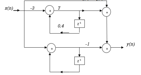
Q7) For the following LTI system H(z)= . Realise the cascade form IIR filter.
A7) H(z)=
The above function can be simplified as
H(z)=

Fig: Cascade IIR Form
Hence, using the above structure and placing the values of 
 …. And similarly,
Q8) For the system given y(n) - y(n-1) +
  y(n-2) = x(n) +
  x(n-1) realise using cascade form?
A8) The system transfer function is given as
H(z) = Y(z)/X(z)
Taking z transform of y(n) - y(n-1) +
  y(n-2) = x(n) +
  x(n-1)
Y(z) -  z-1Y(z) +
  z-2 Y(z) = X(z) +
  z-1 X(z)
H(z)= 
Again, simplifying the above function to get into standard cascade form we ca write
H(z) = 
= H1(z)+H2(z)
H1(z)= 
H2(z)= 
The final structure is shown below

Fig: Cascade Form of H(z) = 
Q9) For the following LTI system H(z)= . Realise the cascade form?
A9) H(z)=
Writing the above in standard form for cascade realisation
H1(z)= 
H2(z)= 
The cascade structure is shown below

Fig: Cascade Form of H(z)=
Q10) Realize the system transfer function using parallel structure H(z)= 
A10) H(z)= 
Taking Z common and then dividing the above function to convert it into standard form for parallel realisation we get
H(z)=Z [  +
+ +
+ ]
]
The parallel structure is shown below

Fig: Parallel Realisation of H(z)= 
Q11) Realize the system transfer function using parallel structure H(z)= 
A11) Converting the above function to standard form using partial fraction technique
H(z)=  +
+ 
Solving for A and B we get
A= 10/3
B= -7/3
H(z) =  +
+ 
H1(z) = 
H2(z) = 
The parallel form realisation is shown below
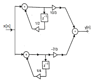
Fig: Parallel Realisation of H(z)= 
Q12) For the transfer function H(z) =  . Realise using cascade form?
A12) H(z) = 
Writing in standard form
H(z) = 
H1(z) = 
H2(z) = 
The cascade structure is shown below

Fig: Cascade Form of H(z) = 
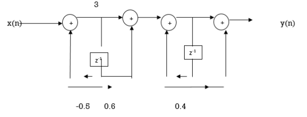
Q13) Obtain the direct form-I, direct form-II, Cascade and parallel form realization of the system y(n)=-0.1y(n-1)+0.2y(n-2)+3x(n)+3.6x(n-1)+0.6x(n-2)
A13) Direct Form I:


Direct form II:
From the given difference equation we have

The above system function can be realized in direct form II
Cascade Form:


Parallel form:


Q14) Design a Discrete Time Low Pass Filter for a voice signal. The specifications are: Passband Fp 4 kHz, with 0.8 dB ripple; Stopband FS 4.5 kHz, with 50dB attenuation; Sampling Frequency Fs 22 kHz. Determine a) the discrete time Passband and Stopband frequencies, b) the maximum and minimum values of H () in the Passband and the Stopband, where () is the filter frequency response.
A14)
a) Recall the mapping from analog to digital frequency 2 F/Fs , with Fs the sampling frequency. Then the passband and stopband frequencies become p 2 4/ 22 rad 0.36 rad, s 2 4.5/ 22 rad 0.41 rad;
b) A 0.8 dB ripple means that the frequency response in the passband is within the interval 1 where is such that 20 log10 (1+) 0.8 These yields 100.04 1 0.096.
Therefore, the frequency response within the passband is within the interval 0.9035 H() 1.096. Similarly in the stopband the maximum value is () 1050/20 0.0031
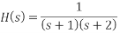
Q15) Given  , that has a sampling frequency of 5Hz. Find the transfer function of the IIR digital filter.
A15)
Step 1:

Step 2:
Applying partial fractions on H(s),


Step 3:

Step 4:
Unit - 4
IIR Filter Design & Realization
Q1) For the following LTI system H(z)= . Realise the cascade form IIR filter.
A1) H(z)=
The above function can be simplified as
H(z)=
Hence, using the above structure and placing the values of 
 …. And similarly,

Fig: Cascade Form realisation of IIR Filter
Q2) Draw block diagram for the function using parallel form H(z)=
A2) H(z)=
Writing above transfer function in standard form for parallel realisation we get
H(z)=-20+
The structure is shown below
Q3) Compare IIR and FIR filters?
A3)
Sr. No | IIR system | FIR system |
1. | IIR stands for infinite impulse response systems | FIR stands for finite impulse response systems |
2. | IIR filters are less powerful that FIR filters, & require less processing power and less work to set up the filters | FIR filters are more powerful than IIR filters, but also require more processing power and more work to set up the filters |
3. | They are easier to change “on the fly”. | They are also less easy to change “on the fly” as you can by tweaking (say) the frequency setting of a parametric (IIR) filter |
4. | These are less flexible. | Their greater power means more flexibility and ability to finely adjust the response of your active loudspeaker. |
5. | It cannot implement linear-phase filtering. | It can implement linear-phase filtering. |
6. | It cannot be used to correct frequency-response errors in a loudspeaker | It can be used to correct frequency- response errors in a loudspeaker to a finer degree of precision than using IIRs. |
Q4) Realise Direct form II and cascade form realizations of

A4) 


Direct form II

Cascade form
Q5) Realise the parallel form for 
A5) A partial fraction expansion of


The corresponding parallel form I realization is shown below

Q6) Draw block diagram for the function using parallel form H(z)=
A6)
H(z)=
Writing above transfer function in standard form for parallel realisation we get
H(z)=-20+
The structure is shown below

Fig: Parallel Realisation of H(z)=
Q7) For the following LTI system H(z)= . Realise the cascade form IIR filter.
A7) H(z)=
The above function can be simplified as
H(z)=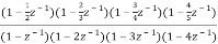

Fig: Cascade IIR Form
Hence, using the above structure and placing the values of 
 …. And similarly,
Q8) For the system given y(n) - y(n-1) +
  y(n-2) = x(n) +
  x(n-1) realise using cascade form?
A8) The system transfer function is given as
H(z) = Y(z)/X(z)
Taking z transform of y(n) - y(n-1) +
  y(n-2) = x(n) +
  x(n-1)
Y(z) -  z-1Y(z) +
  z-2 Y(z) = X(z) +
  z-1 X(z)
H(z)= 
Again, simplifying the above function to get into standard cascade form we ca write
H(z) = 
= H1(z)+H2(z)
H1(z)= 
H2(z)= 
The final structure is shown below
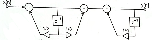
Fig: Cascade Form of H(z) = 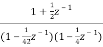
Q9) For the following LTI system H(z)= . Realise the cascade form?
A9) H(z)=
Writing the above in standard form for cascade realisation
H1(z)= 
H2(z)= 
The cascade structure is shown below

Fig: Cascade Form of H(z)=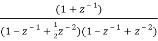
Q10) Realize the system transfer function using parallel structure H(z)= 
A10) H(z)= 
Taking Z common and then dividing the above function to convert it into standard form for parallel realisation we get
H(z)=Z [  +
+ +
+ ]
]
The parallel structure is shown below
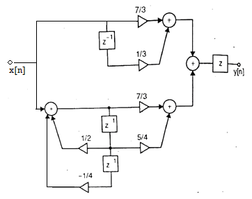
Fig: Parallel Realisation of H(z)= 
Q11) Realize the system transfer function using parallel structure H(z)= 
A11) Converting the above function to standard form using partial fraction technique
H(z)=  +
+ 
Solving for A and B we get
A= 10/3
B= -7/3
H(z) =  +
+ 
H1(z) = 
H2(z) = 
The parallel form realisation is shown below

Fig: Parallel Realisation of H(z)= 
Q12) For the transfer function H(z) =  . Realise using cascade form?
A12) H(z) = 
Writing in standard form
H(z) = 
H1(z) = 
H2(z) = 
The cascade structure is shown below
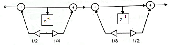
Fig: Cascade Form of H(z) = 
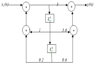
Q13) Obtain the direct form-I, direct form-II, Cascade and parallel form realization of the system y(n)=-0.1y(n-1)+0.2y(n-2)+3x(n)+3.6x(n-1)+0.6x(n-2)
A13) Direct Form I:


Direct form II:
From the given difference equation we have

The above system function can be realized in direct form II

Cascade Form:

Parallel form:

Q14) Design a Discrete Time Low Pass Filter for a voice signal. The specifications are: Passband Fp 4 kHz, with 0.8 dB ripple; Stopband FS 4.5 kHz, with 50dB attenuation; Sampling Frequency Fs 22 kHz. Determine a) the discrete time Passband and Stopband frequencies, b) the maximum and minimum values of H () in the Passband and the Stopband, where () is the filter frequency response.
A14)
a) Recall the mapping from analog to digital frequency 2 F/Fs , with Fs the sampling frequency. Then the passband and stopband frequencies become p 2 4/ 22 rad 0.36 rad, s 2 4.5/ 22 rad 0.41 rad;
b) A 0.8 dB ripple means that the frequency response in the passband is within the interval 1 where is such that 20 log10 (1+) 0.8 These yields 100.04 1 0.096.
Therefore, the frequency response within the passband is within the interval 0.9035 H() 1.096. Similarly in the stopband the maximum value is () 1050/20 0.0031
Q15) Given  , that has a sampling frequency of 5Hz. Find the transfer function of the IIR digital filter.
A15)
Step 1:
Step 2:
Applying partial fractions on H(s),


Step 3:

Step 4:

Unit - 4
IIR Filter Design & Realization
Q1) For the following LTI system H(z)= . Realise the cascade form IIR filter.
A1) H(z)=
The above function can be simplified as
H(z)=
Hence, using the above structure and placing the values of 
 …. And similarly,

Fig: Cascade Form realisation of IIR Filter
Q2) Draw block diagram for the function using parallel form H(z)=
A2) H(z)=
Writing above transfer function in standard form for parallel realisation we get
H(z)=-20+
The structure is shown below

Q3) Compare IIR and FIR filters?
A3)
Sr. No | IIR system | FIR system |
1. | IIR stands for infinite impulse response systems | FIR stands for finite impulse response systems |
2. | IIR filters are less powerful that FIR filters, & require less processing power and less work to set up the filters | FIR filters are more powerful than IIR filters, but also require more processing power and more work to set up the filters |
3. | They are easier to change “on the fly”. | They are also less easy to change “on the fly” as you can by tweaking (say) the frequency setting of a parametric (IIR) filter |
4. | These are less flexible. | Their greater power means more flexibility and ability to finely adjust the response of your active loudspeaker. |
5. | It cannot implement linear-phase filtering. | It can implement linear-phase filtering. |
6. | It cannot be used to correct frequency-response errors in a loudspeaker | It can be used to correct frequency- response errors in a loudspeaker to a finer degree of precision than using IIRs. |
Q4) Realise Direct form II and cascade form realizations of

A4) 


Direct form II

Cascade form
Q5) Realise the parallel form for 
A5) A partial fraction expansion of


The corresponding parallel form I realization is shown below

Q6) Draw block diagram for the function using parallel form H(z)=
A6)
H(z)=
Writing above transfer function in standard form for parallel realisation we get
H(z)=-20+
The structure is shown below

Fig: Parallel Realisation of H(z)=
Q7) For the following LTI system H(z)= . Realise the cascade form IIR filter.
A7) H(z)=
The above function can be simplified as
H(z)=

Fig: Cascade IIR Form
Hence, using the above structure and placing the values of 
 …. And similarly,
Q8) For the system given y(n) - y(n-1) +
  y(n-2) = x(n) +
  x(n-1) realise using cascade form?
A8) The system transfer function is given as
H(z) = Y(z)/X(z)
Taking z transform of y(n) - y(n-1) +
  y(n-2) = x(n) +
  x(n-1)
Y(z) -  z-1Y(z) +
  z-2 Y(z) = X(z) +
  z-1 X(z)
H(z)= 
Again, simplifying the above function to get into standard cascade form we ca write
H(z) = 
= H1(z)+H2(z)
H1(z)= 
H2(z)= 
The final structure is shown below

Fig: Cascade Form of H(z) = 
Q9) For the following LTI system H(z)= . Realise the cascade form?
A9) H(z)=
Writing the above in standard form for cascade realisation
H1(z)= 
H2(z)= 
The cascade structure is shown below

Fig: Cascade Form of H(z)=
Q10) Realize the system transfer function using parallel structure H(z)= 
A10) H(z)= 
Taking Z common and then dividing the above function to convert it into standard form for parallel realisation we get
H(z)=Z [  +
+ +
+ ]
]
The parallel structure is shown below

Fig: Parallel Realisation of H(z)= 
Q11) Realize the system transfer function using parallel structure H(z)= 
A11) Converting the above function to standard form using partial fraction technique
H(z)=  +
+ 
Solving for A and B we get
A= 10/3
B= -7/3
H(z) =  +
+ 
H1(z) = 
H2(z) = 
The parallel form realisation is shown below

Fig: Parallel Realisation of H(z)= 
Q12) For the transfer function H(z) =  . Realise using cascade form?
A12) H(z) = 
Writing in standard form
H(z) = 
H1(z) = 
H2(z) = 
The cascade structure is shown below

Fig: Cascade Form of H(z) = 
Q13) Obtain the direct form-I, direct form-II, Cascade and parallel form realization of the system y(n)=-0.1y(n-1)+0.2y(n-2)+3x(n)+3.6x(n-1)+0.6x(n-2)
A13) Direct Form I:

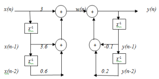
Direct form II:
From the given difference equation we have

The above system function can be realized in direct form II

Cascade Form:


Parallel form:


Q14) Design a Discrete Time Low Pass Filter for a voice signal. The specifications are: Passband Fp 4 kHz, with 0.8 dB ripple; Stopband FS 4.5 kHz, with 50dB attenuation; Sampling Frequency Fs 22 kHz. Determine a) the discrete time Passband and Stopband frequencies, b) the maximum and minimum values of H () in the Passband and the Stopband, where () is the filter frequency response.
A14)
a) Recall the mapping from analog to digital frequency 2 F/Fs , with Fs the sampling frequency. Then the passband and stopband frequencies become p 2 4/ 22 rad 0.36 rad, s 2 4.5/ 22 rad 0.41 rad;
b) A 0.8 dB ripple means that the frequency response in the passband is within the interval 1 where is such that 20 log10 (1+) 0.8 These yields 100.04 1 0.096.
Therefore, the frequency response within the passband is within the interval 0.9035 H() 1.096. Similarly in the stopband the maximum value is () 1050/20 0.0031
Q15) Given  , that has a sampling frequency of 5Hz. Find the transfer function of the IIR digital filter.
A15)
Step 1:

Step 2:
Applying partial fractions on H(s),


Step 3:
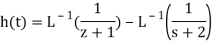
Step 4:


