Unit - 3
Types Flip Flops & Sequential Circuits
Q1) Draw SR and J-K flip flop.
A1)
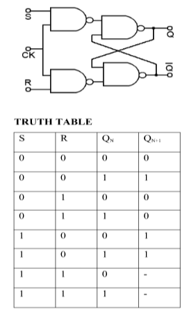
S-R Flip Flop:
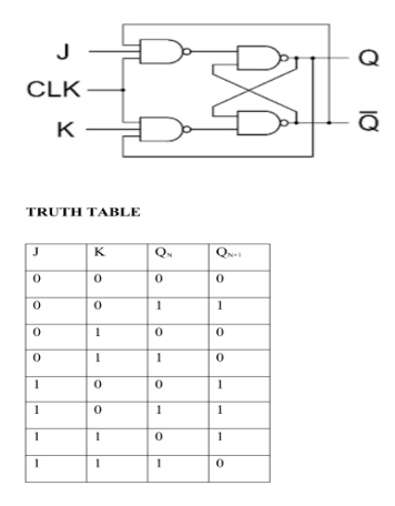
J-K Flip Flop:
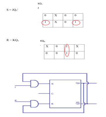
Q2) Convert SR To JK Flip Flop
A2)
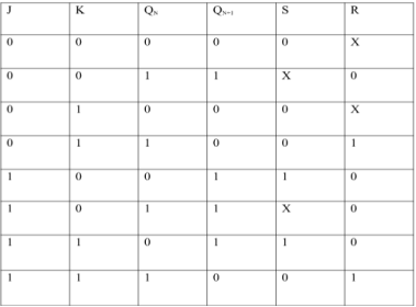
Excitation Functions:
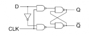
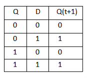
Q3) Draw D and T flip flop.
A3)
D flip flop
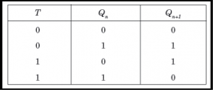
T flip flop

Q4) Explain Modulus of Counter.
A4)
- It counts ten different states and then reset to its initial states.
- A simple decade counter will count from 0 to 9 but the decade counters which can go through any ten states between 0 to 15(for 4 bit counter) can also be made.
Truth table is as follows:
Clock pulse | Q3 | Q2 | Q1 | Q0 |
0 | 0 | 0 | 0 | 0 |
1 | 0 | 0 | 0 | 1 |
2 | 0 | 0 | 1 | 0 |
3 | 0 | 0 | 1 | 1 |
4 | 0 | 1 | 0 | 0 |
5 | 0 | 1 | 0 | 1 |
6 | 0 | 1 | 1 | 0 |
7 | 0 | 1 | 1 | 1 |
8 | 1 | 0 | 0 | 0 |
9 | 1 | 0 | 0 | 1 |
10 | 0 | 0 | 0 | 0 |
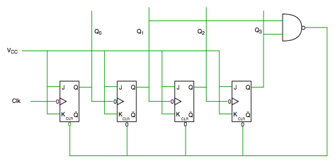
Fig. Decade counter
In the above circuit diagram we used nand gate for Q3 and Q1 and sending this to clear input line as the binary representation of 10 is—
1010
And Q3 and Q1 are 1 here, if we give NAND of these two bits then counter clears at 10 and again starts from the beginning.
Q5) What are counters?
A5)
A Counter stores the number of times a particular event or process has occurred in relationship to a clock signal.
They are used in digital electronics for counting purpose.
They can count specific event happening how many times in the circuit.
For example, in UP counter count increases for every rising edge of clock.
A counter can follow certain sequence based on our design like any sequence 0,1,3,2… .
They can be designed with the help of flip flops.
Q6) Name some of the applications of counter.
A6)
- A Counter stores the number of times a particular event or process has occurred in relationship to a clock signal.
- They are used in digital electronics for counting purpose.
- They can count specific event happening how many times in the circuit.
- For example, in UP counter count increases for every rising edge of clock.
- A counter can follow certain sequence based on our design like any sequence 0,1,3,2…
- They can be designed with the help of flip flops.
Q7) Explain asynchronous counters.
A7)
- In this universal clock is not used and only the first flip flop is driven by main clock and the clock input of rest of the following is driven by output of previous flip flops.
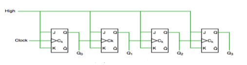
Asynchronous counter

Timing diagram of Asynchronous counter
- It is seen from timing diagram that Q0 is changing as soon as the rising edge of clock pulse is encountered.
- Q1 is changing when rising edge of Q0 is encountered and so on.
In this way ripples are generated through Q0,Q1,Q2,Q3 and therefore it is also called as a RIPPLE counter.
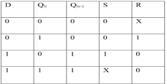
Q8) Convert SR To JK Flip Flop
A8)
SR To JK Flip Flop

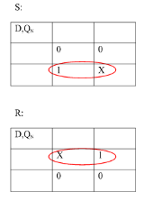
Excitation Functions:

Q9) Convert SR To D Flipflop.
A9)
Excitation Functions:
S = D
R = D‘

Q10) Explain master slave flipflop with timing diagram.
A10)
- When the clock pulse goes high, the slave is isolated; J and K inputs can affect the state of the system. The slave flip-flop is isolated when the CP goes low. When the CP goes back to 0, information is transmitted from the master flip-flop to the slave flip-flop and output is obtained.
- The master flip flop is positive level triggered and the slave flip flop is negative level triggered, hence the master responds prior to the slave.
- If J=0 and K=1, Q’ = 1 then the master goes to the K input of the slave and the clock forces the slave to reset therefore the slave copies the master.
- If J=1 and K=0, Q = 1 then the master goes to the J input of the slave and the Negative transition of the clock sets the slave and thus copy the master.
- If J=1 and K=1, the master toggles on the positive transition and the slave toggles on the negative transition of the clock.
- If J=0 and K=0, the flip flop becomes disabled and Q remains unchanged.
Timing Diagram of a Master flip flop –
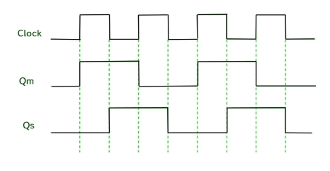
- When the CP = 1 then the output of master is high and remains high till CP = 0 because the state is stored.
- Now the output of master becomes low when the clock CP = 1 and remains low until the clock becomes high again.
- Thus toggling takes place for a clock cycle.
- When the CP = 1 then the master is operational but not the slave.
- When the clock is low, the slave becomes operational and remains high until the clock again becomes low.
- Toggling takes place during the whole process since the output changes once in a cycle.
- This makes the Master-Slave J-K flip flop a Synchronous device which passes data with the clock signal.


