Unit - 1
Introduction to Database Management Systems and ER Model
Q1) Introduce database management systems?
A1) Database
The database is a set of interrelated data used to efficiently retrieve, insert and remove data. It is also used in the form of a table, schema, views, and reports to organize the data, etc.
You can conveniently retrieve, attach, and delete information using the database.
Database management system (DBMS)
A DBMS is a programme that enables database creation, specification and manipulation, allowing users to easily store, process and analyse information.
DBMS provides one with an interface or a tool to conduct different operations, such as building databases, storing data in them, updating data, creating database tables, and much more.
The DBMS also provides databases with privacy and security. In the case of multiple users, it also ensures data consistency.
Some Example of DBMS:
● MySQL
● Oracle
● SQL Server
● IBM DB2
Advantages of DBMS
● Controls database redundancy: It can control data redundancy because it stores all the data in one single database file and that recorded data is placed in the database.
● Data sharing: In DBMS, the authorized users of an organization can share the data among multiple users.
● Easily Maintenance: It can be easily maintainable due to the centralized nature of the database system.
● Reduce time: It reduces development time and maintenance need.
● Backup: It provides backup and recovery subsystems which create automatic backup of data from hardware and software failures and restores the data if required.
● multiple user interface: It provides different types of user interfaces like graphical user interfaces, application program interfaces
Disadvantages of DBMS
● Cost of Hardware and Software: It requires a high speed of data processor and large memory size to run DBMS software.
● Size: It occupies a large space of disks and large memory to run them efficiently.
● Complexity: Database system creates additional complexity and requirements.
● Higher impact of failure: Failure is highly impacted the database because in most of the organization, all the data stored in a single database and if the database is damaged due to electric failure or database corruption then the data may be lost forever.
Q2) What is the purpose of database systems?
A2) It is a set of tools that allows a user to construct and manage databases. In other words, it is general-purpose software that enables users to define, construct, and manipulate databases for a variety of applications.
Database systems are made to handle massive amounts of data. Data management entails both the creation of structures for storing data and the provision of methods for manipulating data. Furthermore, despite system crashes or efforts at illegal access, the database system must preserve the security of the information stored. If data is to be shared across multiple users, the system must avoid any unexpected outcomes.
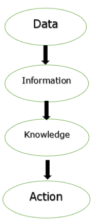
Fig 1: Process of transforming data
The figure above depicts the process of transforming data into information, knowledge, and action in a database management system.
The file system was used as the foundation for the database applications.
The goal of a database management system (DBMS) is to transform the following:
1. Data into information.
2. Information into knowledge.
3. Knowledge to the action.
Uses of DBMS
The main uses of DBMS are as follows −
● Data independence and efficient access of data.
● Application Development time reduces.
● Security and data integrity.
● Uniform data administration.
● Concurrent access and recovery from crashes.
Q3) What is a database system application?
A3) Data is a collection of linked facts and statistics that may be processed to provide information, and a database is a collection of related data.
The majority of data is made up of observable facts. Data assists in the creation of fact-based content. For example, if we have data on all students' grades, we can draw conclusions about top performers and average grades.
A database management system maintains data in such a way that retrieving, manipulating, and producing information becomes easy. The following are some of the most notable DBMS properties and applications.
● ACID Properties - Atomicity, Consistency, Isolation, and Durability are all concepts that DBMS adheres to (normally shortened as ACID). These principles are used to manipulate data in a database through transactions. In multi-transactional situations and in the event of failure, ACID features assist the database stay healthy.
● Multiuser and Concurrent Access - The DBMS enables a multi-user environment, allowing multiple users to access and manipulate data at the same time. Although there are limitations on transactions when many users attempt to handle the same data item, the users are never aware of them.
● Multiple views - For different users, DBMS provides multiple perspectives. A user in the Sales department will see the database in a different way than someone in the Production department. This feature allows users to get a focused view of the database based on their specific needs.
● Security - Multiple views, for example, provide some security by preventing users from accessing data belonging to other users or departments. When entering data into a database and retrieving it later, DBMS provides mechanisms to set limitations. Multiple users can have distinct perspectives with various functionalities thanks to DBMS's many different levels of security features. A user in the Sales department, for example, cannot see data from the Purchase department. It can also be controlled how much data from the Sales department is displayed to the user. Because DBMSs are not kept on disk like traditional file systems, it is extremely difficult for criminals to crack the coding.
Q4) What do you mean by view of data?
A4) View of data in DBMS narrates how the data is visualized at each level of data abstraction? Data abstraction allows developers to keep complex data structures away from the users. The developers achieve this by hiding the complex data structures through levels of abstraction.
There is one more feature that should be kept in mind i.e., the data independence. While changing the data schema at one level of the database must not modify the data schema at the next level.
Data Abstraction
Data abstraction is hiding the complex data structure in order to simplify the user’s interface of the system. It is done because many of the users interacting with the database system are not that much computer trained to understand the complex data structures of the database system.
To achieve data abstraction, we will discuss a Three-Schema architecture which abstracts the database at three levels discussed below:
Three-Schema Architecture:
The main objective of this architecture is to have an effective separation between the user interface and the physical database. So, the user never has to be concerned regarding the internal storage of the database and it has a simplified interaction with the database system.
The three-schema architecture defines the view of data at three levels:
- Physical level (internal level)
- Logical level (conceptual level)
- View level (external level)
1. Physical Level/ Internal Level
The physical or the internal level schema describes how the data is stored in the hardware. It also describes how the data can be accessed. The physical level shows the data abstraction at the lowest level and it has complex data structures. Only the database administrator operates at this level.
2. Logical Level/ Conceptual Level
It is a level above the physical level. Here, the data is stored in the form of the entity set, entities, their data types, the relationship among the entity sets, user operations performed to retrieve or modify the data and certain constraints on the data. Well, adding constraints to the view of data adds the security. As users are restricted to access some particular parts of the database.
It is the developer and database administrator who operates at the logical or the conceptual level.
3. View Level/ User level/ External level
It is the highest level of data abstraction and exhibits only a part of the whole database. It exhibits the data in which the user is interested. The view level can describe many views of the same data. Here, the user retrieves the information using different application from the database.
The figure below describes the three-schema architecture of the database:
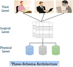
Fig 2: Three-schema architecture
In the figure above you can clearly distinguish between the three levels of abstraction. To understand it more clearly let us take an example:
We have to create a database of a college. Now, what entity sets would be involved? Student, Lecturer, Department, Course and so on…
Now, the entity sets Student, Lecturer, Department, Course will be stored in the storage as the consecutive blocks of the memory location. This is the physical or internal level and is hidden from the programmers but the database administrator is it aware of it.
At the logical level, the programmers define the entity sets and relationship among these entity sets using a programming language like SQL. So, the programmers work at the logical level and even the database administrator also operates at this level.
At the view level, the users have the set of applications which they use to retrieve the data they are interested in.
Data Independence
Data independence defines the extent to which the data schema can be changed at one level without modifying the data schema at the next level. Data independence can be classified as shown below:
Logical Data Independence:
Logical data independence describes the degree up to which the logical or conceptual schema can be changed without modifying the external schema. Now, a question arises what is the need to change the data schema at a logical or conceptual level?
Well, the changes to data schema at the logical level are made either to enlarge or reduce the database by adding or deleting more entities, entity sets, or changing the constraints on data.
Physical Data Independence:
Physical data independence defines the extent up to which the data schema can be changed at the physical or internal level without modifying the data schema at logical and view level.
Well, the physical schema is changed if we add additional storage to the system or we reorganize some files to enhance the retrieval speed of the records.
Instances and Schemas
Instance
We can define an instance as the information stored in the database at a particular point of time. Let us discuss it with the help of an example.
As we discussed above the database comprises of several entity sets and the relationship between them. Now, the data in the database keeps on changing with time. As we keep inserting or deleting the data to and from the database.
Now, at a particular time if we retrieve any information from the database then that corresponds to an instance.
Schema
Whenever we talk about the database the developers have to deal with the definition of database and the data in the database.
The definition of a database comprises the description of what data it would contain and what would be the relationship between the data. This definition is the database schema.
Q5) Write about database language?
A5) Users can interact with DBMS using database languages. There are two types of database languages:
1. The Data Definition Language (DDL)
2. The Data Manipulation Language (DML)
DDL:
DDL is used to define the conceptual schema.
It includes:
A. Entity
B. Attributes and types
C. Relation among entity sets.
The definition also includes constraints on values that can be assigned to a given attribute.
For example:
>create table emp(name varchar(20), emp_id number NOT NULL);
Execution will create an empty table emp. Definitions are stored along with the database.
E.g., Create table, view, index
Alter table.
Drop table, view, index
DML:
i. DML allows user to manipulate data stored in database.
Ii. E.g.
● Data Retrieval
● Data Insertion
● Data Deletion
● Data Modification.
Iii. DML provides commands for data manipulation.
E.g., select name from emp
Where
Salary > 15000;
Iv. DML commands can be either in interactive mode or these commands can be
Embedded in programming languages like C, VB, Java etc.
Types of DML:
a. Procedural:
It requires a user to specify what data is needed and how to retrieve it from database. The user instructs the system to perform a sequence of options on the database to compute the desired result.
b. Non-Procedural:
It requires a user to specify what data is needed without specifying how to get it.
DCL (Data Control Language):
E.g. (commit, rollback, save point, grant, revoke.)
It consists of commands that control the user access to database objects.
Q6) Describe structure of database system?
A6) A system of databases is divided into modules dealing with each of the overall system's responsibilities. A database system's functional components can be narrowly divided into the components of the storage manager and the query processor. The storage manager is essential since a large amount of storage space is usually needed for databases. The query processor is important because it simplifies and promotes access to data by supporting the database system.
It is the responsibility of the database system to convert, at the logical level, changes and queries written in a non-procedural language into an effective sequence of physical level operations.
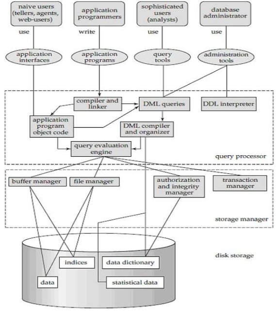
Fig 3: Overall structure of DBMS
The database system divided into three components: Query Processor, Storage Manager, and Disk Storage
● Query processor
It interprets the requests (queries) received from the end user into instructions through an application programme. Also, the user request that is received from the DML compiler is executed.
The Query Processor comprises the following parts:
● DML compiler
The DML statements are processed into low-level (machine language) instructions so that they can be implemented.
● DDL interpreter
The DDL statements are processed into a table set containing metadata (data about data).
● Query optimization
Typically, a question can be converted into any of a variety of alternative assessment plans that all offer the same outcome. The DML compiler also performs query optimization, which is to say, among the alternatives, it selects the lowest cost evaluation plan.
● Query evaluation engine
That executes the low-level instructions that the DML compiler generates.
● Storage manager
A storage manager is a software module that provides an interface between the low-level data stored in the database and the system-submitted application programmes and queries. Interaction with the file manager is the responsibility of the storage manager. Using the file system, which is typically supported by a conventional operating system, raw data is stored on the disc. The storage manager converts the different DML statements into low-level commands for the file system. It is also the duty of the storage manager to store, retrieve, and update data in the database.
The components for the storage manager include:
● Authorization and integrity manager
This ensures role-based regulation of access, i.e., It checks whether or not the individual is entitled to conduct the requested activity.
When the database is updated, the integrity manager checks the integrity constraints.
● Transaction manager
It manages simultaneous access by executing the operations in a scheduled manner in which the transaction is received. It also ensures that the database stays in a consistent state before and after a transaction has been executed.
● File manager
It manages the space of the file and the data structure used in the database to represent information.
● Buffer manager
The cache memory and data transfer between the secondary storage and the main memory are responsible for this.
● Disk storage
It includes the following elements-
● Data files
It stores the data.
● Data dictionary
It includes details about any database object's structure. It is the information repository that regulates metadata.
● Indices
It provides faster retrieval of data items.
Q7) Explain data model?
A7) Data models are used to describe the design of a database at the logical level.
Some of the data models are:
1. Entity-Relationship Model
2. Relational Model
3. Hierarchical Model
4. Network Model
5. Object Relational Model
- Entity-Relationship(E-R) Model:
● The logical structure of a database can be expressed by an E-R diagram.
● Relationships are defined in this database model by dividing the object of interest into an entity and its characteristics into attributes.
● Using relationships, various entities are related.
● To make it easier for various stakeholders to understand, E-R models are established to represent relationships in pictorial form.
The Main Components of ER Diagram are:
a) Rectangles - Entity Sets
b) Ellipses - Attributes
c) Diamond - Relation among entity sets
d) Lines - Connects attributes to entity sets and entity sets to relationships.
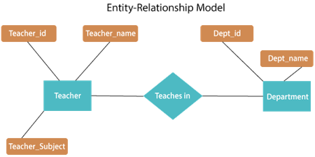
Fig 4: E - R diagram
The above E-R diagram has two entities: Teacher and Department
Teacher entity has three attributes:
Teacher_id
Teacher_name
Teacher_Subject
Department entity has two attributes:
Dept_id
Dept_name
Relation Teaches in gives relationship between Teacher, Department.
Relationship can be of the type:
1:1 → One to one
1:M → One to many
M:1 → Many to one
M:M → Many to many
2. Relational Model:
● Relational model uses a collection of tables to represent both data and the relationships among those data.
● This model is useful for constructing a database that can then be converted into relational model tables.
● Data is arranged in two-dimensional tables in this model and the relationship is preserved by storing a common field.
● In the relational model, the basic structure of data is tables. In the rows of that table, all information relating to a specific category is stored.
Therefore, in the relational model, tables are also known as relations.
Sample relational database
- Teacher Table
Teacher_id | Teacher_name | Teacher_Subject |
1001 | Pritisha | C++ |
1002 | Akon | DBMS |
1003 | Rahul | SE |
1004 | Raj | Data structure |
B. Department Table
Dept_id | Dept_name |
A101 | CSE |
B102 | Electronics |
C103 | Civil |
D104 | Mechanical |
C. Teaches in table
Teacher_id | Dept_id |
1001 | A101 |
1002 | B102 |
1003 | C103 |
1004 | D104 |
3. Hierarchical Model:
● This model of the database organizes information into a tree-like structure with a single root to which all the other information is connected. The hierarchy begins from the root data and extends to the parent nodes like a tree, adding child nodes.
● A child node can only have a single parent node in this model.
● A Hierarchical model uses tree structure to represent relationship among entities.
● This model represents many real-world relationships effectively, such as a book index, recipes, etc.
● Data is structured into a tree-like structure in the hierarchical model with a one-to-many relationship between two different data forms.
For instance, one department can have many classes, many professors and many students of course.
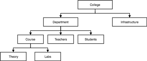
Fig 5: Hierarchical model
4. Network Model:
● Network model uses two different data structures:
a) A record type is used to represent as entity set.
b) A set type is used to represent a directed relationship between two record types.
● This is the Hierarchical model's extension. Data is arranged more like a graph in this model, and is allowed to have more than one parent node.
● Data is more linked in this database model as more relationships are formed in this database model. Also, as the data is more linked, it is also simpler and quicker to access the information. To map many-to-many data relationships, this database model was used.
● This was the most commonly used database architecture prior to the advent of the Relational Model.
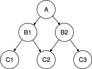
Fig 6: Network model
5. Object Relational Model:
The object-oriented database derivation is the integrity of object-oriented
Programming language systems and consistent systems. The power of object-oriented databases comes from the cyclical treatment of both consistent data, as found in databases, and transient data, as found in executing programs.
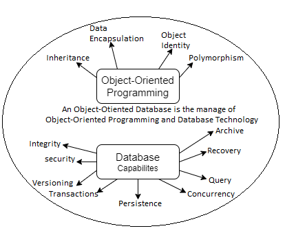
Fig 7: Object - oriented model
Object-oriented databases use small, recyclable separated of software
Called objects. The objects themselves are stored in the object-oriented
Database. Each object contains of two elements:
1. Piece of data (e.g., sound, video, text, or graphics).
2. Instructions, or software programs called methods, for what to do with
The data.
There are two types of ORM:
a. Object-Oriented Data Model (OODM)
b. Object-Relational Data Model (ORDM)
These models are used to handle objects:
1) To provide support for complex objects.
2) To provide user extensibility for data types operators and access methods.
3) There should be mechanism to support:
a) Abstract data type.
b) Data of type ‘procedure’.
c) Rules.
Q8) What do you mean by entity?
A8) We will group only similar data together in a database and store them under one group name called Entity / Table. It helps to determine which information is stored where and under what name. In a whole database, it reduces the time to search for a specific data.
In short, all of the world's living and non-living entities form an organism. If that makes it easier, one should accept all nouns as entities.
● Strong entity
Entities with their own attributes as primary keys are referred to as powerful entities. For example, STUDENT, has STUDENT ID as its primary key. It is, therefore, a strong entity.
● Weak entity
Weak entities are entities which cannot form their own attribute as a primary key. These entities can derive their primary keys from the combination of their attributes and from their mapping entity's primary key.
Example: Consider an object with CLASS and Segment. As an attribute, the SECTION has SECTION ID and NAME. However, SECTION ID alone may not be a primary key, as it fails to say which course it is associated with.
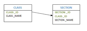
Fig 8: Example of entity
● Composite entity
Entities that engage in several or many interactions are referred to as composite entities. In this situation, we will have one more hidden entity in the relationship, aside from the two entities that are part of the relationship. By using the primary keys of the other two entities, we will create a new entity with the relationship, and create a primary key.
Consider the instance of several students enrolled in several courses. We are developing STUDENT and COURSE in this case. We then build one more table for the 'Enrolment' relationship and name it as STUD COURSE. Add into it the COURSE and STUDENT primary keys, which form the new table's composite primary key.
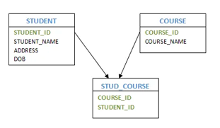
Fig 9: Composite entity
● Recursive entity
If there is a correlation with the same entities, then such entities are referred to as recursive entities. For example, manager-employee mapping is a recursive entity. Managers are mapped to the same employee entity here. Another instance of providing recursive entities is the department's HOD.
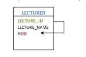
Fig 10: Recursive entity
Q9) Write short notes on attributes?
A9) Attributes
An attribute may have a single value, or a number of values, or a variety of values. Furthermore, each attribute can contain certain data types, such as a numeric value only, or an alphabet only, or a combination of both, or a date or a negative or a positive value, etc.
It is split into different forms, based on the values an attribute can take.
● Simple Attribute: These types of attributes have properties that cannot be further divided. For example, the attribute STUDENT ID, which cannot be further divided. Passport Number is a unique value that cannot be divided.
● Composite Attribute: It is possible to further split this kind of attribute into more than one basic attribute. For instance, an individual's address. Here, the address can be further divided as Door#, Street, City, State and Pin, which are simple attributes.
● Derived Attribute: Derived attributes are those whose meaning can be derived from other entity attributes in the database. For example, it is possible to obtain a person's age from the date of birth and current date. Examples of derived attributes are average wage, annual salary, total marks of a student, etc.
● Multi - valued Attribute: At any point in time, these attributes may have more than one value. The manager can have more than one worker working for him, an employee can have more than one email address, and the examples are more than one house etc.
● Stored Attribute: The attribute that gives the value of the derived attribute is referred to as the Stored Attribute. In the above case, age is derived from the date of birth. The Date of Birth is also a stored attribute.
Q10) Explain Constraints?
A10) Constraints
● A mapping constraint is a data constraint representing the number of entities to which a relationship set can relate to another entity.
● It is most useful to define relationship sets involving more than two sets of individuals.
● There are four possible mapping cardinalities for the binary relationship set R on an entity set A and B. They are as follows
- One to one (1:1)
- One to many (1:M)
- Many to many (M:M)
One to one: As we have seen in the example above, only one instance of an entity is mapped to one instance of another entity. Consider the Department's HOD. Just one HOD in one department exists. That is, the relationship between the HOD agency and the Department is 1:1.
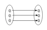
Fig 11: One to one mapping
One to many: As we can guess now, there is one instance of an entity linked to many instances of another entity between one and several relationships. In his department, one manager oversees several employees.
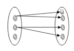
Fig 12: One to many mapping
Many to many: This is a relationship where multiple entity instances are linked to multiple entity instances.

Fig 13: Many to many mapping
Q11) What are keys?
A11) Keys are the entity's attributes, which define the entity's record uniquely.
Several types of keys exist.
These are listed underneath:
● Composite key
A composite key consists of two attributes or more, but it must be minimal.
● Candidate key
A candidate key is a key that is simple or composite and special and minimal. It is special since no two rows can have the same value at any time in a table. It is minimal since, in order to achieve uniqueness, every column is required.
● Super key
The Super Key is one or more of the entity's attributes that uniquely define the database record.
● Primary key
The primary key is a candidate key that the database designer chooses to be used as an identification mechanism for the entire set of entities. In a table, it must uniquely classify tuples and not be null.
In the ER model, the primary key is indicated by underlining the attribute.
● To uniquely recognize tuples in a table, the designer selects a candidate key. It must not be empty.
● A key is selected by the database builder to be used by the entire entity collection as an authentication mechanism. This is regarded as the primary key. In the ER model, this key is indicated by underlining the attribute.
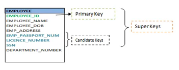
Fig 14: Shows different keys
● Alternate key
Alternate keys are all candidate keys not chosen as the primary key.
● Foreign key
A foreign key (FK) is an attribute in a table that, in another table, references the primary key OR it may be null. The same data type must be used for both international and primary keys.
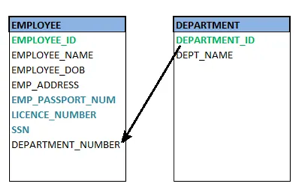
Fig 15: Foreign key
● Secondary key
A secondary key is an attribute used exclusively (can be composite) for retrieval purposes, such as: phone and last name.
Q12) What is the entity relationship model?
A12) Entity relationship model
● The Entity-Relationship model (ER model) is a type of entity-relationship model. It's a data model at a high level. The data elements and relationships for a given system are described using this model.
● It creates a database's conceptual architecture. It also creates a very convenient and easy-to-design data view.
● The database structure is depicted as a diagram called an entity-relationship diagram in ER modeling.
Let's say we're creating a database for a school. The student will be an object in this database, with attributes such as address, name, id, age, and so on. There will be a relationship between the address and another entity with attributes such as city, street name, pin code, and so on.
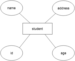
Fig 16: Example of ER
Component of ER model -
The following components are composed of an ER Diagram:
- Entity
- Attributes
- Relationships
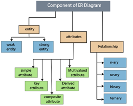
Fig 17: Component of ER model
Q13) Write about relationships?
A13) In the Entity-Relation Model, a relationship is used to define the relationship between two or more entities. In the ER diagram, it is illustrated by a diamond shape.
For example, in college student studies, employees work in a department. Here, the links are 'research in' and 'works in'.
Degree of Relationship
A partnership is called the degree of a relationship in which a variety of different individuals participate.
Degree of relationship can be categorized into the following types:
1. Unary Relationship:
A relationship in which a single group of individuals is involved is referred to as a unary relationship. For instance, in a company, an employee manages or supervises another employee.
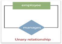
Fig 18: Unary relationship
2. Binary Relationship: When a relationship includes two people, it is considered a binary relationship.
3. Ternary Relationship: When a relationship contains three individual sets, a ternary relationship is called.
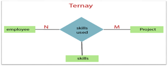
Fig 19: Ternary relationship
4. N-nary Relationship:
If a relationship includes more than three entity sets, an n-ary relationship is named.
Q14) Write the design issues?
A14) We learned how to create an ER diagram in the earlier portions of the data modeling. We also explored various approaches to defining entity sets and their relationships. We also learned how to use different design shapes to represent a relationship, an entity, and its attributes. Users, on the other hand, frequently misunderstand the concept of the elements and the ER diagram's design process. As a result, the ER diagram has a complex structure and some flaws that do not match the characteristics of a real-world business model.
The following are the fundamental design challenges of an ER database schema:
- Use of Entity Set vs Attributes
The structure of the real-world enterprise being simulated, as well as the semantics associated with its properties, determine the utilization of an entity set or attribute. When a user uses an entity set's primary key as an attribute of another entity set, it results in an error. Instead, he should do so through the relationship. In addition, although the primary key qualities are implied in the relationship set, we designate them in the relationship sets.
2. Use of Entity Set vs. Relationship Sets
It's tough to tell whether an entity set or a relationship set is the best way to express an item. The user must specify a relationship set for describing an activity that occurs between the entities in order to comprehend and determine the appropriate use. If the object must be represented as a relationship set, it is best to keep it separate from the entity set.
3. Use of Binary vs n-ary Relationship Sets
The relationships depicted in databases are often binary relationships. Non-binary relationships, on the other hand, can be represented by a number of binary relationships. We can, for example, define and describe a ternary relationship called 'parent,' which can refer to a child, his father, and his mother. Such a relationship can also be represented by two binary partnerships, such as a mother and father who may have a child together. As a result, a set of discrete binary relationships can be used to represent a non-binary relationship.
4. Placing Relationship Attributes
In the placement of connection qualities, cardinality ratios can become an effective measure. As a result, rather than any relationship set, it is preferable to correlate the attributes of one-to-one or one-to-many relationship sets with any participating entity sets. The choice of whether to place the provided attribute as a relationship or entity attribute should reflect the characteristics of the real-world business being simulated.
For example, rather than determining it as a separate entity, if there is an entity that may be identified by a combination of participating entity sets. Many-to-many relationship sets must be associated with this sort of characteristic.
As a result, it necessitates a thorough understanding of each component involved in designing and modeling an ER diagram. The most basic prerequisite is to examine the real-world enterprise and the relationships between different entities or attributes.
Q15) Convert ER diagrams into tables?
A15) Using notations, the database can be represented, and these notations can be reduced to a set of tables.
Each entity set or relationship set can be represented in tabular form in the database.
The ER diagram is given below:
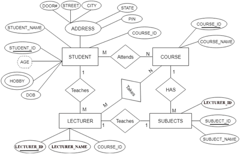
Fig 20: ER diagram
There are some points for converting the ER diagram to the table:
● Entity type becomes a table.
In the given ER diagram, LECTURE, STUDENT, SUBJECT and COURSE forms individual tables.
● All single-valued attribute becomes a column for the table.
In the STUDENT entity, STUDENT_NAME and STUDENT_ID form the column of STUDENT table. Similarly, COURSE_NAME and COURSE_ID form the column of COURSE table and so on.
● A key attribute of the entity type represented by the primary key.
In the given ER diagram, COURSE_ID, STUDENT_ID, SUBJECT_ID, and LECTURE_ID are the key attribute of the entity.
● The multivalued attribute is represented by a separate table.
A hobby is a multivalued feature inside the student table. Thus, multiple values cannot be expressed in a single column of the STUDENT table. We therefore generate a STUD HOBBY table with the STUDENT ID and HOBBY column names. We create a composite key by using both columns.
● Composite attribute represented by components.
Student address is a composite attribute in the given ER diagram. CITY, PIN, DOOR#, Path, and STATE are included. These attributes will merge as an individual column in the STUDENT table.
● Derived attributes are not considered in the table.
In the STUDENT table, the derived attribute is age. It can be determined by measuring the difference between the present date and the date of birth at any time.
You can convert the ER diagram to tables and columns using these rules and assign the mapping between the tables.
The following is the table structure for the given ER diagram:
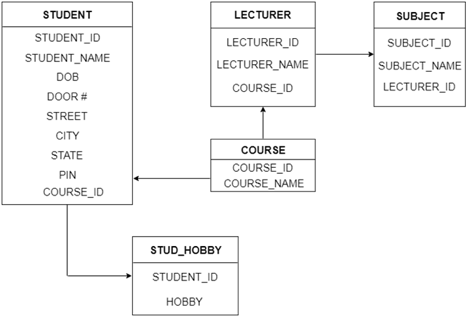
Fig 21: Table structure
Q16) Write the difference between DML and DDL?
A16) Following are the important differences between DDL and DML.
Sr. No. | Key | DDL | DML |
1 | Stands for | DDL stands for Data Definition Language. | DML stands for Data Manipulation Language. |
2 | Usage | DDL statements are used to create database, schema, constraints, users, tables etc. | DML statement is used to insert, update or delete the records. |
3 | Classification | DDL has no further classification. | DML is further classified into procedural DML and non-procedural DML. |
4 | Commands | CREATE, DROP, RENAME and ALTER. | INSERT, UPDATE and DELETE. |