Unit – 2
Beam and types transverse loading on beams
Q1) Explain Beam and types transverse loading on beams in details.
A1) Beam:
Beam is a structural member used to resist the applies load. Generally, beam is used to resist the shear force, vertical load and bending moment. Beam is a flexible member which can resist the compression and tension force. For example, in reinforcement, steel have ability to resist the tension, while concrete used to resist the compression force. There is different type of beam, based on shape, based on geometry, based on supports, based on equilibrium conditions. The types of beam are given in detail which is given below:
There are two types of loading on beam-
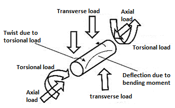
1. Axial loading (loading which is along longitudinal axis of beam)
2. Transverse loading (Loading which is perpendicular to the longitudinal axis of beam)
Transverse loading on beams:
Transverse loading is a load applied vertically to the plane of the longitudinal axis of a configuration, such as a wind load. It causes the material to bend and rebound from its original position, with inner tensile and compressive straining associated with the change in curvature of the material.
Transverse loading is also known as transverse force or crosswise force.
Q2) Define Beam and types of beam support.
A2) Beam:
Beam is a structural member used to resist the applies load. Generally, beam is used to resist the shear force, vertical load and bending moment. Beam is a flexible member which can resist the compression and tension force.
Types of beam supports
Based on support:
The types of beam based on support are:
Simply supported beam
It is the type of beam in which on end is roller and other end is pinned. The simply supported beam is the simplest structure element because the both ends are rest on support. In this type of beam the one end is free to rotate and have not any ability to resist moment.
Continuous beam:
Continuous beam is the type of beam in which have more than two supports distributed through its entire length.
Over hanging beam:
Over hanging beam is the type of beam in which both or single end are extended beyond the support. It may have any number of supports but the condition the one or both end should be extended. The both ends in over hanging beams are roller support.
Double over hanging:
In this type of beam the both ends of beam are over hanging beyond the supports is known as double over hanging beam. There is difference between overhanging beam and double over hanging beam. In over hanging beam the one side is over hanging while in double over hanging the both side is over hanging beyond the supports.
Cantilever beam:
Cantilever beam is the type of beam in which one end is fix and one is free. This beam can resist the shear force and bending moment. Cantilever beam is mostly used in buildings, bridges, and trusses etc.
Fixed beam:
In this type of beam the both end is fixed. Fixed beam resists the vertical load, horizontal load and also moment. This type of beam is used in building, trusses or other structures.
Trussed beam:
Trussed beam is the type of beam in which cables or rod is added for getting the more strength to form a truss.
Q3) The simply supported beam shown in fig. Has overhanging portion on one side. Find the reaction at the support.

A3) The given beam has a hinged support at A and a roller support at B. The free body diagram is shown in fig. Which show two reaction at A and one reaction at B end.
There are three equation of static equilibrium:


Fig. Free body diagram
Applying equation of static equilibrium:


Considering z- axis passing through A, and taking moments all the forces about z – axis.

On solving Eq.2 and Eq. 3 we get;

The negative sign of reaction indicate that Ay will be inn the downward direction instead of upward as shown in free body diagram.
Q4) Classify the beam on the basis of equilibrium condition.
A4) Based on equilibrium condition:
The type of beam based on equilibrium conditions are given below:
1. Statically determinant
2. Statically indeterminate
Statically determinant:
A beam is said to be determinant if it can be analyzed by basic equilibrium condition. These three conditions should be obeying then it will be statically determinant. The three conditions are as follow:
•The sum of all vertical forces is equal to zero.
•The sum of all horizontal forces is equal to zero.
•The sum of moment forces is equal to zero.
The example of statically determinant beams is cantilever beam, simply supported beam.
Statically indeterminant:
A beam is said to be in determinant if it can be analyzed by basic equilibrium condition. These three conditions should be obeying then it will be statically in determinant. The end can be found by using basic equilibrium equation and also addition of other conditions like strain energy method, virtual energy method etc. the example statically in determinant beam is continuous beam, fixed beam.
Q5) Derive the Bending Theory Equation.
A5) In order to compute the value of bending stresses developed in a loaded beam, let us consider the two cross-sections of a beam HE and GF, originally parallel as shown in fig (a).
When the beam is to bend it is assumed that these sections remain parallel i.e. H'E' and G'F', the final position of the sections, are still straight lines, they then subtend some angle θ.
Consider now fiber AB in the material, at a distance y from the N.A, when the beam bends this will stretch to A'B'.
Therefore, strain in fiber AB =Change in length /original length
=A’B’-AB/AB
But from fig 1 (a,b)
AB=CD and CD=C’D’
=A’B’-C’D’/C’D’
Since CD and C'D' are on the neutral axis and it is assumed that the Stress on the neutral axis zero. Therefore, there won't be any strain on the neutral axis
=(R+y)θ-Rθ / Rθ
=(Rθ+yθ-Rθ / Rθ
=y/R
However stress/strain =E
Where E=Young modulus of elasticity
Therefore equating the two strains as obtains from the two relation i.e.
σ/E = y/R or σ/y = E/R…1
Consider any arbitrary a cross-section of beam, as shown above now the strain on a fibre at a distance ‘y' from the N.A, is given by the expression
σ= E.y/R
If the shaded strip of area dA then the force on the strip is
F = σδA = (E/R) y.δA
Moment about the neutral axis would be F.y = (E/R) y2δA
The total moment for the whole cross section is therefore equal to
M=∑ (E/R) y2 δA = E/R ∑y2δA
Now the term ∑y2δA is the property of the material and is called as a second moment of area of the cross-section and is denoted by a symbol I.
Therefore
M= (E/R) I…..2
Combining equation 1 and 2 we get
M/I = σ/y = E/R
This equation is known as the Bending Theory Equation. The above proof has involved the assumption of pure bending without any shear force being present. Therefore, this termed as the pure bending equation. This equation gives distribution of stresses which are normal to cross-section i.e., in x-direction.
Q6) A cantilever beam AB of length L and constant flexural rigidity EI carries a moment Mo at its free end A. Derive the equation of the deflection curve and determine the slope and deflection at A.
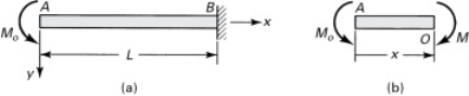
A6) From the free-body diagram of fig. (b), observe that the bending moment is +Mo throughout the beam. Thus, the third of equation becomes

Integration yields

The constant of integration c1 can be found from the condition that the slope is zero at the support; therefore, we have υ′(L) = 0 from which c1 = −MoL. The slope is then

Integrating, we obtain

The boundary condition on the deflection at the support is υ′(L) = 0 which yields c2 = MoL2/2EI. The equation of the deflection curve is thus a parabola:

However, every element of the beam experiences the same moments and deformation. The deflection curve should, therefore, be part of a circle. This inconsistency results from the use of an approximation for the curvature,the error is very small, however, when the deformation υ is small.
The slope and deflection at A are readily found by letting x = 0 in Eqs.

The minus sign indicates that the angle of rotation is counterclockwise.
Q7) Explain Shear modulus and shear stress distribution.
A7) Section modulus
The maximum bending stress in a beam is calculated as σb = My / Ic, where y is the distance from the neutral axis to the extreme fibre, Icis the centroidal moment of inertia, and M is the bending moment.
The section modulus combines the y and Ic terms in the bending stress equation:
Z = Ic / y
Using the section modulus, the bending stress is calculated as σb = M / Z. The utility of the section modulus is that it characterizes the bending resistance of a cross section in a single term. This allows for optimization of a beam's cross section to resist bending by maximizing a single parameter.
Shear stress distribution:

Q8) What is the section modulus (Z) for a rectangular section?
A8) The modulus of section may be defined as the ratio of moment of inertia to the distanceto the extreme fiber.
It is denoted by Z.
Z= I/y;
For rectangular section,
I = bd3/12 & y = d/2.
Z= bd2/6.
Q9) Find the modulus of section of square beam of size 300×300 mm.
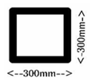
A9) Here, a = side of square section = 300 mm.
For square section,
I = a4/12. y= a/2.
Z = I/y = a3/6
= 3003/6
= 4.5 × 106 mm3.
Q10) A Steel rod 200 mm diameter is to be bent into a circular arc section. Find radius of curvature. Take f = 120N/mm2 & E = 2×10⁵ N/mm2.
A10) Given:
Diameter of Steel rod = 200mm; y = d/2 = 100mm.
f= 120N/mm2.
E= 2×10⁵N/mm2.
By flexural equation we have f/y = E/R
R = 2×10⁵/ 120 ×100
= 166.6m.


