Unit - 2
Types of dams and stability
Q1) What is gravity dam?
A1)
- A structure which is designed to resist the external forces by its own weight is called as gravity dam.
- Design of such dam is done in such way that its own weight resists the external force. Gravity dam structure is more rigid and most durable and requires less maintenance.
- Gravity dam may be constructed of masonry or concrete. Hence concrete dam is a gravity dam. Concrete gravity dam are more preferred these days and mostly constructed.
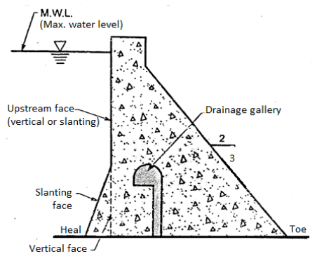
Fig 1: Concrete Gravity Dam
- Site selection for such dam is prime importance and site for dan should be selected in such way that, there exists a natural foundation strong enough to take the huge amount of weight of the dam
- Gravity dam is generally straight in plan and in case of special cases, it may be slightly curve.
Q2) How water pressure acts on gravity dam?
A2)
Water pressure (P)
- In concrete gravity dam, the water pressure is more major and important external force. The weight of the water stored on the upstream side on the dam exerts the horizontal water pressure and it can be estimated from the rule of hydrostatic pressure distribution. Hydrostatic pressure variation or distribution is triangular in shape as shown in Fig.
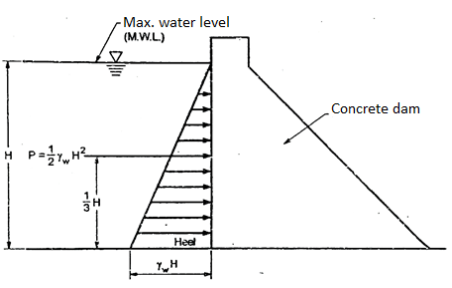
Fig 2: Water Pressure Distribution
- For vertical upstream face of dam, the intensity of water pressure at the water surface is zero and at the base, it is equal to
 H.
H.
P = Resultant force caused by external water pressure acting at  H from base =
- For upstream face partly vertical and partly with the slope as shown in fig., then resultant water force(P) is resolved into the components as
i) Horizontal component ( ) =
) =  acting at
  H from the base
Ii) Vertical component
Q3) What is silt pressure?
A3)
Pressure
- Silts are get deposited against the upstream face of the dam.. Force exerted by silts with external water pressure can be expressed Rankine's formula as follows:
 =
= 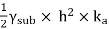 and this silt force act at
- For upstream inclined face, the vertical weight of the silt supported on the siope also acts as a vertical force.
- If any data of silt is not available or reliable, then U.S.B.R. Recommendation can be taken into consideration in which deposited silt can be taken as equivalent to a fluid exerting a force with a unit weight equal to 3.6 kN/m' horizontally and with a unit weight of 9.2 kN/ m' vertically.
Q4) Explain uplift pressure in detail.
A4)
Uplift pressure
- Seepage of water is occurred through cracks, fissures and pores of foundation material and also through dam body. This water is then come to bottom through the joints between the dam body and its foundation at the base.
- This seeping water finally exert an uplift pressure on the base of the dam. Hence uplift pressure is major external force and has to be considered in the design of dam.
- Uplift pressure reduces the downward weight of the body of the dam and ultimately affects the dam stability.
- According to the recommendation of United States Bureau of Reclamation (U.S.B.R.), the uplift pressure intensities at the heel and at the toe is equal to their respective hydrostatic pressures and shown by straight lines in between as shown in Fig.
- Fig. shows uplift pressure diagram 1.e. U diagram when drainage gallery is not provided.
Uplift pressure = 


Fig 3: Uplift Pressure
Q5) Give wave pressure diagram.
A5)
Wave pressure
- When the wind blows, the waves are produced on the surface of stored water in the reservoir. These waves produce wave pressure towards the downstream side.
- Wave pressure developed on the surface of reservoir depends upon the wave height.
Let hw= wave height
 = 2.4
= 2.4
 = 19.62KN/m
Total force caused by wave action act at  above water surface of reservoir.
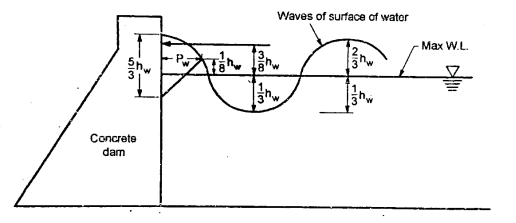
Fig 4: Wave Pressure
Q6) How ice pressure acts on gravity dam?
A6)
Ice pressure
- In cold region of countries, ice is formed on the surface of the reservoir, which further can expand or melt. Hence the dam face should able to resist the force exerted by the melting ice which has magnitudes varies from 250 kN/m² to 1500 kN/m² depending upon the atmospheric temperature.
- For the sake of design, the average value like 500 kN/m² can be allowed and considered under the ordinary conditions.
Q7) Explain weight of dam in case of gravity dam.
A7)
Weight of the dam
- The weight of the dam and its foundation has prime importance because they are major resisting force. A unit length of the dam is taken in two dimensional (2-D) analysis.
- The overall cross section of dam is split up into triangles and rectangles of which, weight with their centre of gravity is determined.
- Then resultant of all downward forces gives the total weight of the dam which acts through centre of gravity of the dam.
Q8) Explain earthquake force in detail.
A8)
Earthquake forces or seismic forces
- In the earthquake prone area, if the dam is to be constructed, then earthquake impact should be considered.
- The effect of an earthquake is equivalent to give an acceleration to the foundation of the dam in the direction in which the waves travels at the moment.
- Earthquake waves can be moved in any direction sake of design, the earthquake wave force should be resolved horizontally and vertically or resolved into horizontal and vertical components.
- Therefore the accelerations developed by an earthquake has to be taken account.

Fig 5: Earthquake Force
Q9) Explain elementary profile of gravity dam.
A9)
Elementary Profile Of Gravity Dam
- A fig shows a right angle triangle which is elementary profile of gravity dam subjected to only external water pressure on upstream side. This right angled triangle has zero width at the water level and base width say B at the bottom.

Fig 6: Elementary Profile Of Gravity Dam
- Shape of elementary profile of a dam is quite same to the shape of the hydraulic pressure distribution.
When the reservoir is empty
- For empty reservoir, self weight of the dam is a only single force acting on a dam and this self weight act a distance
 B from the heel.
 - Line of the action of self weight w impact the maximum possible stabilizing moment about the toe without developing the tension at toe.
- For empty reservoir, the vertical stress distribution at the base is given by the following relation.
 =
=  (1 +
(1 +  )
)
 =
=  (1 -
(1 -  )
)
When the reservoir is full
Condition 1: The resultant® of hydrostatic water pressure (P) self weight(w) and internal water pressure or uplift pressure passes through lower middle third point.
Condition 2: For full reservoir condition, the dam is safe in sliding.
Q10) Explain practical profile of gravity dam.
A10)
Practical Profile Of Gravity Dam
Elementary profile found safe if it is modified in a practical profile by adding
- Free board to prevent water splashing to provide additional storage.
- Width at top to accommodate.
- Additional upstream width to balance load due to top width.

Fig 7: Practical Profile
Recommendation
To keep resultant within middle third of the base in the reservoir the above that is top width the free board are added arbitrarily.
These are:
- Free board FB = 0.9
- Top width a = 6 to 10m
- Addition upstream width = a/16
Stability requirement for gravity dam
- Resistance to sliding
- Resistance to sliding
- Resistance to compressive stresses
- Resistance to internal tension
- Resistance to overturning
Q11) How foundation treatment helps in case of gravity dam.
A11)
Foundation treatments
- Pre-cooling of concrete
The concrete os cooled before it is placed. This is done by cooling the aggregate by refrigerated water, blowing air through them, cooling of sand some times, refrigerated water can be used to manufacture of concrete.
2. Post cooling of concrete
In this case, refrigerated water is circulated through pipes which are embedded in concrete in each lift The cooling process gets started immediately after a block of concrete it is laid and processed is further continued till the temperature falls to mean annual temperature of the locality.
3. Thin wall tubing with expansion coupling are made into coils and placed in the middle of each lift for the purpose of circulating the cool water.
4. Control of cracking can be achieved by providing contraction joints at suitable spacing.
5. Control of cracking can be achieved by using low heat cement for the concrete.
6. Control of cracking can be done by restricting the height of lift upto 1.5m
7. Control of craking also done by using power percentage of cement in the concrete for the interior of the blocks say about 80% of that for the exterior.
Q12) Explain various types of joints in detail.
A12)
Joints in dam
The various types of joints used in gravity dam are:
Types of joints
1. Construction
2. Expansion-Contraction
(1) Transverse joint
(II) Longitudinal joint
- Construction joints
- Construction joints are in horizontal plane and in vertical plane. These are provided for ease in construction of dam.
- Generally in gravity dam concrete is placed in lifts so as to avoid heat of hydration at the same time horizontal joints are introduced between successive lifts of concrete.
- To develop proper bond between two lifts the top surface of the concrete laid in lower lift is freed of by brushing to remove foreign material. Sometime wet sand blasting is used.
- The surface is rounded and 1.25 cm thick layer of rich cement mortar is applied to develop proper bond between lower lift and new concrete.
2. Expansion and contraction joints
- The cracks are formed mainly due to shrinkage of concrete, tensile stresses formed in concrete and temperature variations, and if these are not properly controlled by providing suitable contraction joint they destroy monolithic action of the structure.
- Therefore suitable contraction joints are provided in gravity dam.
The two types of contraction joints are:
(I) Transverse joint
- These are provided normal to the axis of dam. These are vertical and extend from foundation to the top of dam. These joints allows contraction and prevent cracks in the dam.
- Its spacing depends upon various factors such as topography of site, temperature and its variation etc. the usual spacing of joint is between 12 to 18 m. The joint is filled with as plastic joint filler.
(II) Longitudinal joint
- These are provided parallel to the axis of dam to prevent longitudinal axis.
- The spacing of longitudinal joint is limited to 15 m and 30 m depending upon foundation condition.

Fig 8: Longitudinal joint
Q13) Explain keys and water seal.
A13)
Keys
- Keys are provided in longitudinal joints to permit transfer of shearing stresses from one block to the other key ways may be of several shape like triangular, trapezoidal or through shaped.
- Their provision in transverse joint is optional.
Water stops or water seal
These are provided in both types of joints it prevents leakage of water. These are either made of metal plastics, or synthetic rubbers.
Q14) What do you mean by gallery?
A14)
Galleries
- Gallery is a passage provided in the body of dam. These may run parallel or transverse to the axis of dam and located at different levels.
- These all are inter connected by shaft, lifts, stair etc. The usual sizes of galleries are 2 to 2.5 m wide and 2.5 to 4m deep and corners are rounded.
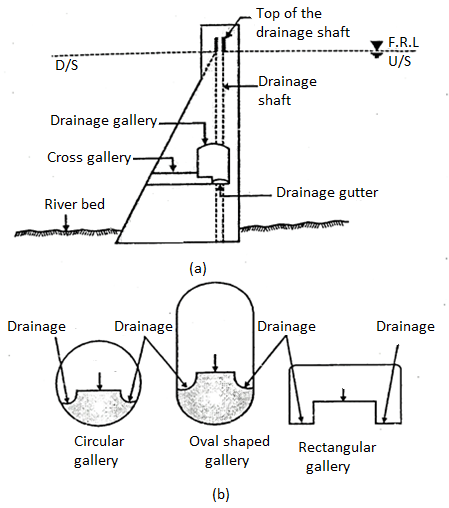
Fig 9: Galleries
Functions of Drainage Galleries in Dam
The purpose of providing galleries are:
1. For inspection of dam from inside.
2. To drain ff seepage water through the body of dam
3.It provide access to spillway gate.
4. It helps in locating pumps, observation devices.
5.It provides access for grouting.
Types of drainage galleries in dam
(i) Foundation gallery (drainage gallery)
This document was truncated here because it was created in the Evaluation Mode.


