Unit-1
Introduction to Various Design Philosophies
Q1) Explain introduction to various design philosophies of R.C structure?
A1) Concrete is strong in compression but week in tension
Steel is reinforced suitable at the place where concrete is weak in tension such combination of steel and concrete
The purpose of R.C structure is increase strength of concrete section and to reduce the size of structural member
Various design philosophies of R.C structure are
Reinforced concrete is used to construct various structures

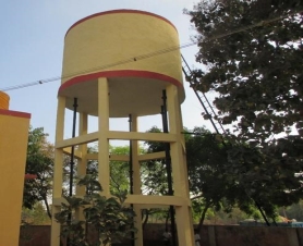 Fig no 1Building

Fig no 2 Fig no 3
Flyover Water tank
Q2) Explain various type of RCC structure also limitations of WSM over LSM
A2) Following are the various methods for RCC structure
1. Working stress methodology (WSM).
2. Ultimate load methodology (ULM).
3 Limit state methodology (LSM).
Limitations of WSM strategies over LSM
Q3) Explain advantages and disadvantages of RCC
A3) Advantages of reinforced concrete
1. Strength
It has excellent Tensile likewise as compressive strength a pair of malleability
2. Ductility
Ductility of structures is increase thanks to steel reinforcement
3. Durability
R.C. structures are more durable
4. Mould ability
The flexibility of reinforcement and therefore the liquidness of concrete makes the R.C. member to be mould in any form thus it's appropriate for architectural demand.
5. Porosity
RC members are impermeable to wet
6. Fire place resistance
R.C. structures are additional fireplace resistance than alternative materials such as steel and wood
7. Economy
R.C.C is cheaper than steel and pre stressed concrete
Disadvantages of R.C.C
RCC has followed disadvantages
1. Weight of R.C. structures are measure over different materials
2. Significant formwork is needed for R.C. members
3. RC structures take a lot of times to realize its full strength
Q4) Explain the working stress methods, ultimate load methods, limit state methods
A4) Working Stress Method (WSM)
Ultimate Load Method
Load factor= Collapse load / working load
Limit State methods
Q5) What are the assumption created in working stress methods
A5) Assumptions created in working stress method
Q6) Explain the comparison between balanced, under reinforced. Over reinforced section
A6) Comparison between various sections
S R NO | Description | Balanced Section | Under reinforcement section | Over reinforcement section |
1 | Steel | Steel provided as per requirements | Steel provide less than requirements | Steel provided more than requirements |
2 | Neutral axis | X =XC | X<XC | X>XC |
3 | Actual stress of concrete | ( | ( | ( |
4 | Actual stress in steel | ( | ( | ( |
5 | Moment of resistance | MR =T*Z =C*Z | MR = T*Z | MR =C*Z |
6 | Economic | economical | More economical | costlier |
7 | Safety | More safe | Fails in tension | Fails in compression |


Q7) A reinforced concrete beam section of size 300 mm x 700 mm effective depth is reinforced with 3 bars of 20 mm diameter in tension. The concrete mix and HYSD steel reinforcement used are of grade M20 and Fe415 respectively.
A7) Find
1) Depth of neutral axis.
2) Type of reinforced section.
3) Moment of resistance.
4) Maximum stress induced in material WSM is recommended.
Answer:
Given,
b = 300 mm
d = 700 mm
To find: x, MR and σc b c
Sol2
For M20, σc b c = 7 N/mm2 and m = 280 / 3 *  c b c = 230/ 3* 7 = 13.33
For Fe415, σs t = 230 N/mm2
Area of steel = n *  /2 * d 2 = 942.5 mm 2
Step 1: Depth of critical neutral axis:
 c b c / (
 s t /m) = X c / (d –X c)
0.406 = X c / (700 – X c)
700 = x c + 2.464 X c
X C = 202
Step 2: Actual depth of neutral axis (x):
= m. A s t( d – x)
= 13.33x942.5 (700– x)
150 x2 = 8.794 x 10⁶ – 12563.53x
150 x2 + 12563.53x - 8.794 x 106 = 0
Solving quadratic equation, we get
x = 203.85 mm
Step 3: Type of beam section:
Since, x > X c, then section is over reinforced section and will be fails
in compression.
Step 4: Moment of resistance:
MR = C* Z
MR =  c b c/ 2 .b .x. (d –
  x/3)
x/3)
= 300 X 203.85 (700–203.85 /3)
= 135.29 x 10⁶ N.mm = 135.29 K N. m
Step 5: maximum stress induced in material:
Since the section fails in compression,
 c b c max = 7 N/ mm 2
Corresponding maximum stress in steel:
=  c b c /
 s t/m) = x – (d-x)
= 93.33/  s t = 0.41086
 s t max= 227.1 N/mm2
Q8) What are assumption in limit state design
A8) ASSUMPTION IN LIMIT STATE DESIGN
F y/1.15Es + 0.002 f y
Q9) What are the design steps for finding ultimate moment of resistance
A9) DESIGN STEPS
Given
Grade of concrete
Grade of steel
Size of beam
Reinforcement provided
If X u = X u max …………….balanced
If X u< X u max …………….under reinforced
If X u> X u max …………….over reinforced
Equating the compression force and tension force
0.36 * f c k * b * X u * + A s c * f s c = 0.87 * f y * A s t
From this find X u
M u = 0.36 * f c k * b * X u * (d- 0.42 * X u) + A s c * f s c * (d- d’)
This equation is valid for balanced and under reinforced section
If the section is over reinforced section then take X u = X u max in above equation and use the same equation for finding M u .Do not increase the depth of the beam for over reinforced section.
Given
Grade of concrete and steel
Size of beam
Ultimate moment
M u is given
For balanced section X u = X u max
M u limiting = 0.36 * f c k * b * X u max * (d- 0.42 * X u max)
So M u 2 = M u – M u limiting
A s t limit = M u limit / 0.87 * f y * (d – 0.42 * X u max)
A sc = M u2/ f s c (d- d’)
As t 2 = A s c * f s c/ 0.87 f y
As t =A s t limit + A s t 2
Where
d = effective depth of beam
d’= distance between extreme compression fiber to the center of comp reinforced
b = width of beam
X u = depth of actual neutral axis
X u max = depth of critical neutral axis
A s t = total area of tensile reinforced in mm2
F c k = characteristic compressive strength of concrete
F y = characteristic strength of steel
M u limit = limiting M R of a section without compression reinforced in K N m
M u = ultimate M R
A s c= area of compression reinforcement
Q10) Explain L beam brief
A10)L BEAM
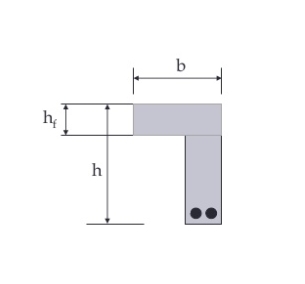
Fig no 4 L BEAM
In bending the beam take the tension force and slab take compression force since the L beam receive their load from one side only they are subjected to consideration amount of torsion moments so L beam are subjected to bending moments shear force and torsion moments
Moment carried by flange of L beams
The moment M1 causes torsion in the beam and is known as the torsion moments which is restricted by the rectangular portion only and the flanged does not contribute to torsion moment of resistance
Moment carried by flanged of L beam and the slab
The central load W cause bending moments in the beam which is joined restricted by the rectangular portion of the beam as well as the flanged
Changes in floor level may be accommodated by either an L beam or building up one side of an inverted T beam
Code recommends that effective width of the flanged of beam may be taken as follows
2. for isolated L beams ,lesser of
Where
b f = effective width of flanged
b w =breadth of rib
b = actual width of flanged
I o = distance between points of zero moments in beam
The design principles to be followed while designing L beam
Given
Step 1: determine width of flanged
Steps 2: fixed up a suitable depth
Steps 3: calculate MR of the section assuming the failure of concrete to occur .if the moment of resistance is greater than bending moments assumed depth is ok otherwise either increases the depth of the section or provide additional reinforcement in compression side in addition to the tension side
Steps 4: calculate the amount of tension steel for actual bending moments treating it as a balanced section
Steps 5: check for the shear and provide shear reinforced
Steps 6: check of deflection
Steps 7: check for end anchoring and development length


