Unit - 4
DC Machines-motoring and generation
Q1) Give detailed description of generating and motoring mode of DC machine.
A1) Generating Action:
The basic circuit model for a dc machine is shown below:
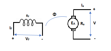
Fig 1 Generating Action
The machine operates in generating mode when the armature current is in the direction of induced emf Ea.
V = Ea – Ia Ra Ea> V
Pmech = Ea Ra = Pelect
The output power,
P0 = VIa
EaIa – VIa = Ia2 Ra
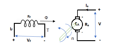
Fig 2 Torque Developed
In this mode, the torque of electromagnetic origin is in opposite direction of rotation of armature.
[Pmech]gross = Shaft power = [Pmech]net + Rotational loss.
Motoring Action
In this mode, the armature current Ia flows opposite to the emf induced i.e., Ea. The basic circuit showing this mode is below:
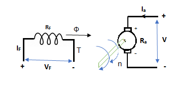
Fig 3 Motoring Action
(Ea – Eb) is called as back emf here as it opposes the armature emf.
V = Ea + IaRa
Electrical power connected to mechanical form
Pelec / net = EaIa
Power input, Pi = V Ia
V Ia – EaIa = Ia2Ra = armature copper loss.
The back emf is given as
Eb = 
Q2) How does a voltage is built up in a shunt generator.
A2) A DC Shunt Generator at no load as shown in figure below. The switch in the field circuit is supposed open and the armature of DC Shunt Generator is driven at rated speed. Due to the presence of small residual flux in the field poles, DC Shunt Generator will have a small voltage at its terminal.
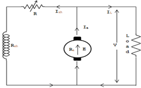
Fig 3 DC Shunt Generator
A small current will start flowing through the field circuit of DC Shunt Generator which in turn will produce magnetic flux and if the produced magnetic flux adds the residual magnetic flux, then net flux will increase and the generated voltage will increase corresponding to point J on the Magnetization curve as shown in figure below.
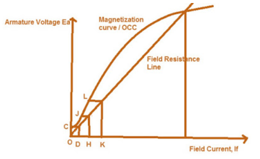
Fig 4 Magnetization Curve
As the generated voltage has increased, therefore the field current will also increase to O-K corresponding to which the Generated Voltage across the Terminals of DC Shunt Generator will increase to point L. In the same manner the voltage will continue to build up till the point of intersection of Field Resistance Line and Magnetization curve / Open Circuit Characteristics of DC Shunt Generator. Beyond point of intersection of Field Resistance Line and Magnetization curve / Open Circuit Characteristics the voltage won’t build up as in that case the generated voltage will not be able to drive the required field current. Thus, the stable point at which the voltage will remain fix is the voltage corresponding to point of intersection of Field Resistance Line and Magnetization curve / Open Circuit Characteristics.
Q3) Derive Torque equations of DC machine.
A3) Motor Torque
1) Armature Torque (Ta) of motor –
Power developed = Ta × 2πN W
As electrical power is converted to mechanical =EbIb
So, power developed = Power converted
Ta × 2πN = EbIb


We can also conclude from the above eqn.

For series,


For shunt,
 is constant practically.

2) Shaft Torque (Tsh) –
The torque doing useful work is called as shaft torque, Tsh.
Motor output =Tsh × 2πN


Due to iron and friction losses in motor Ta – Tsh difference torque exists called as lost torque.
Q4) An 8 pole DC shunt generator with 730 wave connected armature conductor s and running at 500 rpm supplies a load of 11.5Ω resistance at terminal voltage of 250v. The armature resistance is 0.3Ω and field resistance of 235Ω. Find armature current and induced emf.
A4) Load current = V/R = 250/11.5 =21.74A
Shunt current = 250/235 =1.064A
Armature current = 21.74+1.064 = 22.8A
Induced emf = 250 + (22.84 x 0.3) = 256.8V
Q5) A short shunt DC compound generator supplies 210 A at 100v the resistance of armature, series field and shunt field windings are 0.05Ω, 0.03Ω and 50Ω respectively. Find EMF generated.
A5) For short shunt connection armature terminal voltage Va = 100+ (210x0.03) =106.3V
Shunt field current = 106.3/50 = 2.13A
Armature current =210+2.13 =212.13A
Induced emf = 106.30 + (212.13 x 0.05) = 116.9V
Q6) The speed of a 37.3kW series motor working on 500V supply is 600 rpm at full load and 90% efficiency. If the load torque is made 250 N-m and a 5ohm resistance is connected in series with the machine, calculate the speed at which the machine will run. Assume armature and field resistance of 0.5ohm?
A6) Load torque in first case T1=37300/2 (600/60) =593.65 N-m
Input current Ia1=37300/0.9*500=82.9A
T2=250 N-m. So, finding Ia2
For series motor T α φ Ia α Ia2
T1 α  and T2 α

 =82.9*
 =53.79A
Eb1=500-(82.9*0.5) =458.5V
Eb2=500-53.79(5+0.5) =204.11V


Q7) The armature of a four pole DC shunt generator is lap wound and generates 210v when running at 500 rpm. Armature has 132 slots, with 6 conductors/slot. If armature is rewound, wave connected, find EMF generated with same flux/pole running at 300rpm.
A7) Total conductors Z = 132x6= 792
The emf E= 
For lap winding P=A
E= 
210= x 792 x 500/60
 = 31.82mWb
If wave connected number of parallel paths = 2
The emf E=  = (31.82x10-3 x 792 x 300/60) (4/2)
E= 252V
Q8) A 15kW 400V 350rpm dc shunt motor has current 30A at full load. The moment of inertia of rotating system is 6.5kg-m2. The starting current be 1.2 times of full load current. Find the full load torque?
A8) Full load output = 15000W
Speed N=350rpm=5.83rps
Output = Tω
T = 15000/2 x5.83 = 409.3N-m
Q9) A DC series motor operates at 600 rpm with line current of 110A from 220v main. Its armature resistance is 0.2Ω and field resistance is 0.1ohm Find the speed at which motor runs at a line current of 25A, given flux at this current is 45% of flux at 110A.
A9) 
 = 0.45
E1=220 – (0.2+0.1) x 110=187V
E2=220 – (0.2+0.1) x 25 = 212.5V

N2= 1515.15rpm
Q10) A belt driven,120kWshunt generator running at 310 rpm on 220v busbars continues to run as a motor when the belt breaks, then taking 10kW. What will be its speed with armature resistance of 0.03 Ω field resistance of 60Ω and contact drop under each brush is 1v.
A10) Input current = 120x1000/220 = 545.45A
Shunt current Ish= 220/60 = 3.67A
Armature current Ia= 545.5-3.67=541.83A
E2= 220 – (541.83 x 0.03)- 2x1[drop across brush]
E2=205.74V
The armature current Ia now becomes Ia= 545.5+3.67= 549.17A
As the system here runs as a generator.
E1= 220 – (549.17 x 0.03) +1x2 = 201.5V

As shunt current is constant so  =
= 


N2= 316.5rpm
Q11) The input to 230v DC shunt motor is 12kW. Calculate the torque developed, efficiency. No load current=6A, No load speed=1200rpm armature, resistance=0.5Ω, shunt field resistance= 110Ω.
A11) No load input =230x6=1380W
Ish=230/110 =2.1A
Armature current at no load = 6-2.1 = 3.9A
No load armature Cu loss= 3.92 x 0.5= 7.6W
Constant losses = 1380 – 7.6 = 1372.4W
When input is 12kW
Input current = 12000/230 = 52.17A
Armature current = 52.17 – 2.1=50.07A
Armature Cu loss = 50.072 x 0.5 =1253.69W
Total loss=1253.69+1372.4=2626.09W
Output= 12000-2626.09 =9373.9W
Efficiency = 9373.9/12000=0.781=78.1%
Q12) A 230v DC series motor is running at a speed of 550rpm and draws 50A. Calculate at what speed the motor will run when developing half the torque. Total resistance of armature and field is 0.08Ω.
A12)  =
=
Ta α φIa
Ta α 
 )2
)2
 )2
)2
Ia2 = 50x0.707=35.35A
E1=230- (50x0.08) =226V
E2=230- (35.35x0.08) =227.17V
 =
=
 =
=
N2= 781.97rpm
Q13) A 230v shunt motor has an armature resistance of 0.3Ω and field resistance of 140Ω. The motor draws 5A at 1600rpm at no load. Calculate the speed of motor?
A13) Ish= 230/140= 1.643A
Ia1=5-1.643=3.36A
Ia2=50-1.643=48.36A
E1= 230- (3.36x0.3) =226.34V
E2= 230- (48.36x0.3) =215.5V
 =
=
 =
=
N2= 1523.37rpm
Q14) A DC series motor drives a load, the torque if which varies as the square of the speed. Assuming magnetic circuit to remain unsaturated and negligible motor resistance. Calculate the reduction in motor terminal voltage which will reduce the motor speed half the value it has on full load.
A14) Ta α φIa
Ta α 
Ta α 
N2 α 
 =
=
 =
=
Let V1 and V2 be voltage across motor in two cases.
E1=V1 and E2=V2
 αIa1
αIa1
 =
=

 x 2
x 2
 =
= 
% reduction in voltage = V1-V2/V1 x 100 = 4-1/4 x100 = 75%
% change in motor current = Ia1-Ia2/Ia1 x 100 = 50%
Q15) What is critical resistance and critical speed of DC shunt generator.
A15) If the field resistance is increased to OA, then Field Resistance line intersect the OCC curve at point p, and hence there will not be voltage build up beyond point p.
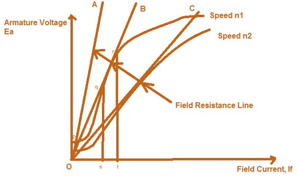
Fig 5 Critical Resistance
Now, if shunt field resistance is such that OB represents the Field resistance line then as clear from the figure above, the lone is intersecting the OCC curve at many points between q and r, therefore the field current will fluctuate between s and t and hence the voltage generated at the terminals of DC Shunt Generator will vary from qs to rt resulting in unstable condition. If we find the slope (tanƟ) of the Field Resistance Line then we will get Field Resistance value which is known as Critical Filed Resistance. Here Critical Field Resistance = tanƟ = qs/Os
As clear from the figure above, if the field resistance is more than the Critical Field Resistance then there will not be voltage build up in DC Shunt Generator. See in the figure OA is shunt field resistance which is more than Critical Field Resistance OB (check by slope, slope of OA is more than slope of OB), hence there is no voltage build up in DC Shunt Generator.
Fig 6 Armature voltage v/s Field Current
Suppose the field resistance is OC and DC Shunt Generator is running at a speed of n1 for which the stable point of its terminal voltage is C. Now the speed of DC Shunt Generator is reduced to n2 therefore the OCC curve will also move downward as shown in figure. It should be noted here that the same field resistance line OC is now tangent to the new OCC curve and therefore will create an unstable condition of operation of DC Shunt Generator. This speed n2 is hence called Critical Speed.