MI
Unit 4Current and Voltage MeasurementsQ1) What is a shunt?A1) A shunt is a low-ohm resistor that can be used to measure current. Shunts are always employed when the measured current exceeds the range of the measuring device. The shunt is then connected in parallel to the measuring device. The entire current flows through the shunt and generates a voltage drop, which is measured afterwards. Using Ohm's law and the known resistance, this measurement can then be used to calculate the current
Q2) What is a potential divider?A2) A potential divider is a simple circuit which takes advantage of the way voltages drop across resistors in series. The idea is that by using two resistors in series it is possible to divide a voltage and create a different voltage between them.Q3) Explain the working of potential divider?A3) A potential divider is a simple circuit which takes advantage of the way voltages drop across resistors in series. The idea is that by using two resistors in series it is possible to divide a voltage and create a different voltage between them. In the example below two identical resistors are in series with power supply. The total voltage across the circuit is ‘Vin’ however this total voltage is split between our two resistors meaning ‘Vout’ is at a different voltage. The amount by which the voltage drops over across each resistor depends on the relative values of each resistor and the total resistance.
Figure 1. Potential Divider CircuitThe formula for working out the voltage drop across two resistors in series is:
Q4) How much current will flow through a 20Ω resistor connected in series with a 40Ω resistor when the supply voltage across the series combination is 12 volts dc. Also calculate the voltage drop produced across each resistor
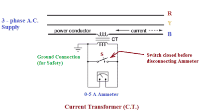
Q5) What are instrument transformers?A5) The Basic function of Instrument transformers is to step down the AC System voltage and current. The voltage and current level of power system is extremely high. It is difficult and costly to design the measuring instruments for measurement of such high- level voltage and current.Q6) What is current transformer?A6) Current transformer is used to step down the current of power system to a lower level to make it feasible to be measured by small rating Ammeter (that is 5A ammeter). A typical connection diagram of a current transformer is shown in figure below.
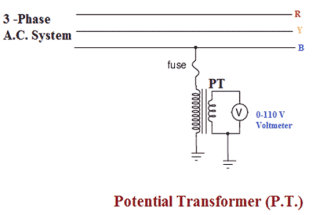
Figure 2. Current TransformerPrimary of C.T. is having very few turns. Sometimes bar primary is also used. Primary is connected in series with the power circuit. Therefore, sometimes it also called series transformer. The secondary is having large no. of turns. Secondary is connected directly to an ammeter. As the ammeter is having exceedingly small resistance. Hence, the secondary of current transformer operates almost in short- circuited condition. One terminal of secondary is earthed to avoid the large voltage on secondary with respect to earth which in turns reduce the chances of insulation breakdown and also protect the operator against high voltage. More ever before disconnecting the ammeter, secondary is short circuited through a switch ‘S’ as shown in figure above to avoid the high voltage build up across the secondary.Q7) What is a Potential transformer?A7) Potential transformer is used to step down the voltage of power system to a lower level to make is feasible to be measured by small rating voltmeter i.e. 110 – 120 V voltmeter. A typical connection diagram of potential transformer is shown in figure below.
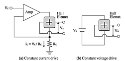
Figure 3. Potential Transformer Primary of P.T. has large no. of turns which is connected across the line generally between on- line and earth. Hence, sometimes it is also called the parallel transformer. The Secondary of P.T. has few turns and connected directly to voltmeter. Since the voltmeter has large resistance the secondary of P.T operates almost in open circuited condition. One terminal of secondary of P.T. is earthed to maintain the secondary voltage with respect to earth which assures the safety of operators.Q8) What is Hall sensor?A8) Among magnetic sensors, a sensor that utilizes the Hall effect is called a Hall sensor. Hall sensors include several parts. First, it contains a Hall element which outputs a Hall voltage, (HV), created via the Hall effect. Second, it contains a Hall IC which makes the Hall output to a High/Low digital output from the IC process. Third, it contains a Linear Hall IC which amplifies and linearizes the Hall output.
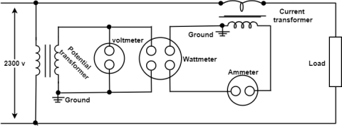
Figure 4. Hall SensorsQ9) Explain the application of Instrument transformer?A9) To measure the high value of electric current i.e Current Transformer (CT)For measure high value of electric voltages or potential difference i.e Potential Transformer(PT) To measure electric power with uses of both CT and PT
Figure 5. CT & PTIn the above diagram to measure the current, potential difference, and power in a circuit having a high current and high potential difference. Notice that the potential transformer is always connected in parallel of a circuit and the current transformer is connected in series of the circuit.Q10) What are the application of Potential transformer?A10) The potential transformers are used in the protecting relaying scheme because the potential coils of the protective device are not directly connected to the system in case of the high voltage. Therefore, it is necessary to step down the voltage and also to insulate the protective equipment from the primary circuit.
(I = V/R). |
|
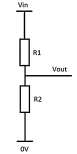
Vout = Vin ( R2/R1 + R2) |
A4) RT = R1 + R2 = 20 + 40 = 60 Ω I = Vs/ RT = 12/60 = 0.2 = 200 mA VR1 = I x R1 = Vs( R1/ R1 + R2) = 12 ( 20/20 + 40) = 4 volts VR2 = IxR2 = Vs(R2/R1+R2) = 12( 40/20+ 40) = 8 volts |
|
|
|
|


0 matching results found