UNIT 7
Voltage Regulators
A regulator is a circuit which converts unregulated dc in to regulated dc. The word regulation means the output is constant irrespective of input voltage and load current. The regulated output dc is connected load.
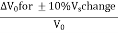
LINE REGULATION: The line regulation is defined as the variation of output voltage ΔV0 that occurs when supply voltage Vs increases or decreases by a specified amount. The output voltage change is expressed as a percentage of normal dc output voltage V0.
Line Regulation = |
LOAD REGULATION: The load regulation is defined as the regulator performance in relation to load current changes. When the load current changes from zero to full load the output voltage changes by an amount ΔV0. The load regulation ΔV0 expressed as a percentage of normal output voltage.
Line Regulation = |

RIPPLE REJECTION: The ripple rejection is a measure of how much the voltage regulator attenuates the supply voltage ripple. It is usually expressed in decibels. If a supply ripple voltage is of Vrs and an output ripple of Vro then
Ripple Rejection = 20log [ |

Key takeaways
- Easy to use. It greatly simplifies power supply design. Due to mass production, it is low in cost. Conveniently used for local regulation. IC voltage regulators are versatile
Voltage regulator is a circuit which keeps its output voltage constant in spite of change in input voltage or load current. Input to the voltage regulator is unregulated or pulsating dc voltage obtained from filter and rectifier. Its output is constant dc voltage which is almost ripple free. Fixed voltage series regulator using op-amp is shown in figure. The op-amp is used as a comparator. From figure below the voltage at inverting terminal is given by
VB = Vout. The voltage at non inverting terminal at node A is Zener voltage VZ VA = VZ. Due to the concept of virtual ground VA = VB V0 VZ |
Thus, the output voltage is constant equal to Zener voltage. The series pass transistor is used to supply the additional load current which op-amp alone cannot supply.
|
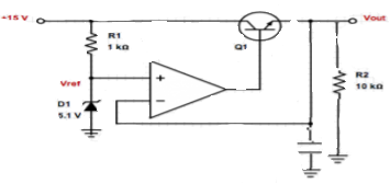
Fig 1 Series Op-Amp Regulator
Key takeaways
- The C is a large capacitor of the order 50-100uF the function of C is to help to supply fast demands on regulator. To eliminate the possibility of any oscillatory behaviour of the regulator.
|
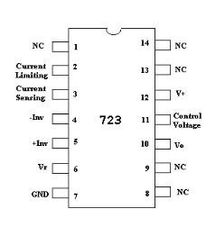
Fig 2 IC 723 Pin Configuration
It is a 14-pin DIP chip. The pin diagram is shown above and the block diagram is discussed below. As we can see from the block diagram that Zener diode produces a constant voltage of 7V at the reference amplifier input. The Zener diode is forced to operate at a fixed point by the constant current source so that the output from the Zener diode is a fixed voltage. There are two transistors Q1 which is series pass transistor and Q2 which is current limit transistor.
|
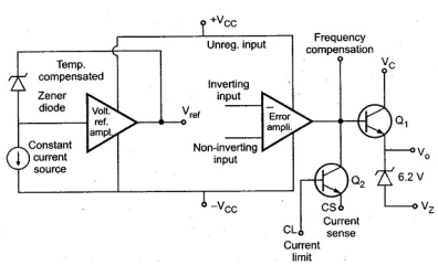
Fig 3 Functional Block Diagram of IC723
The error amplifier compares a sample of the output voltage applied at the inverting input terminal. The reference voltage Vref applied at the non-inverting input terminal. The error signals controls, the conduction of Q1. These two sections are not internally connected but the various points are brought out on the IC package.
Key takeaways
- The Zener diode is forced to operate at a fixed point by the constant current source so that the output from the Zener diode is a fixed voltage. There are two transistors Q1 which is series pass transistor and Q2 which is current limit transistor.
Low Voltage Regulator using IC 723
|
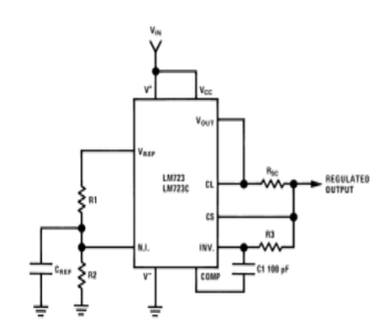
Fig 4 Low voltage Regulator using IC 723
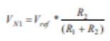
The voltage at the non-inverting terminal of error amplifier due to R1 and R2 is
The difference between VN1 and output voltage V which is directly fed back to the inverting terminal is amplified by the error amplifier. The output of the error amplifier drives the ass transistor Q1 so as to minimize the difference between the NI and Inv input of error amplifier. Since Q1 is operating as an emitter follower
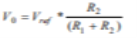
As we see V+ = +VCC, V- = GND, R3 = R1||R2. Then Vo = VNI Vo = 7.15xR2/(R1+R2) The typical value of reference voltage Vref is 7.15V. So that output voltage VO is always less than7.15V. By suitably designing the value of R1 and R2 the output voltage ranging from 2V to 7V can be built.
|
High Voltage Regulator Using IC 723
|
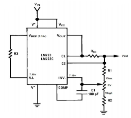
Fig 5 High Voltage Regulator Using IC 723
A high voltage 7 volts output to 35V outputs regulator can be made using IC 723 is shown in figure above. The non-inverting terminal is connected directly to Vref through R3 so that voltage at non inverting terminal is Vref. The error amplifier operates as non-inverting amplifier with voltage gain of
Av = 1+ (Rf/R1)
Output voltage gain is given as
Av = 7.15(1+ Rf/R1)
Key takeaways
- For high voltage regulation voltage gain is
Av = 1+ (Rf/R1)
2. Output voltage gain is given as
Av = 7.15(1+ Rf/R1)
|
Fig 6 Switching Regulator
The switching power supply is shown in above figure. The bridge rectifier and capacitor filter are connected directly to the ac line to give unregulated dc input. The Thermistor limits the high initial capacitor charge current. The reference regulator is a series pass regulator. Its output is a regulated reference voltage Vref which serves as supply voltage for all other circuits.
Transistor Q1 and Q2 are alternatively switched off and on. These transistors are either fully on or cut-off so that they dissipate little power. These transistors drive the primary of main transformer. The secondary centre tapped and full wave rectification is achieved by diodes. This unidirectional square wave is next filtered through a two stage LC filters to produce output voltage Vo. The regulation is achieved by a feedback circuit consisting of PWM.
Key takeaways
- Power dissipation is less. The Small size transformers are used. Efficiency is very high. Power handling capacity is high.
References:
1. Ramakant. A. Gayakwad, “Op-Amps & Linear Integrated Circuits”, 3rd Edition, PHI
2. S. Salivahanan & Bhaaskaran, “Linear Integrated Circuits”, 1st Edition, Tata McGraw Hill.
3. T.R Ganesh Babu, “Linear Integrated Circuits”, 3rd Edition, SciTech Publication
4. Sergio Franco, “Design with op-amp &Analog Integrated Circuits”, 3rd Edition, Tata McGraw Hill
5. “Operational Amplifiers and Linear IC’s”, David A. Bell, 2
nd edition, PHI/Pearson, 2004
6. “Linear Integrated Circuits”, D. Roy Choudhury and Shail B. Jain, 2nd edition, Reprint 2006, New Age International


