UNIT-6
Mixed –Type Descriptions
Our definition of mixed-type description is an HDL code that mixes different types (styles) of descriptions within the same module. Here, the code is written using more than one type of description in the same module.
In fact, it is very common to write mixed descriptions because each part of the selected system may be written best by a certain type of description.
The first style is to use behavioral statements to model the addition and the division. This style is somewhat easy to write because HDL has built-in addition and division functions.
A second option is to use data-flow or structural description. These descriptions can be implemented to describe the specific adder. It is, however, hard to implement these descriptions in complex algorithms such as division.
The third option is to use a mixture of two types (styles) of descriptions: structural or data-flow for addition and behavioral for division. This description is referred to here as a mixed type.
VHDL has an extensive set of predefined data types such as bit, std_ logic, array, and natural. In some applications, other data types that are not included in the basic HDL package are needed.
Examples of such types are weekdays, weather, or grades. These are userdefined types. To instantiate a user-defined type, the predefined word type is used. An example of instantiating a user-defined type is:
type week_days is (mon, tues, wed, th, fr, sat, sun);
This statement declares a user-defined type by the name of week_days, and type is a predefined word; the elements or members of week_days are mon, tues, wed, th, fr, sat, and sun.
A subtype of a type can be declared by using the predefined word subtype, as shown below:
subtype failed is grades range D to I;
signal scores : failed;
where failed is a subtype of grades and has a range from D to I, range is a predefined attribute, so scores can be assigned a value of D, F, or I.
Another example is:
subtype values is integer range 10 to 100;
signal x : values;
Signal x can be assigned an integer value from 10 to 100
Packages constitute an essential part of VHDL description. Packages allow the user to access built-in constructs. Packages may include type and subtype declarations, constant definitions, function and procedure, and component declarations. VHDL has default built-in packages that include predefined words such as bit, bit_vector, and integer. In addition to the defaults, the user can attach a variety of packages to the VHDL module.
A package consists of a declaration and a body. The declaration states the name (identifier) of the package and the names (identifiers) of types, procedures, functions, and components. The body of the package contains the code for all the identifiers listed in the declaration.
An Example of a VHDL Package package conversions is type wkdays is (mon, tue, wed, th, fr); procedure convert (a : in bit; b : out integer); function incr (b : std_logic_vector) return std_logic_vector; end conversions; package body of conversions is written as: procedure convert (a : in bit; b : out integer) is begin ....... end convert; function incr (b : std_logic_vector) return std_logic_vector is begin ... end incr; end conversions;
In the above example the name of the package is conversions; the package contains Type wkdays, Procedure convert, and function incr. The package body lists the code of the procedure convert and function incr.
An Example of a VHDL Package library ieee; use ieee.std_logic_1164.all; package codes is type op is (add, mul, divide, none); end; use work.codes; entity ALUS2 is port (a, b : in std_logic_vector (3 downto 0); cin : in std_logic; opc : in op; z : out std_logic_vector (7 downto 0); cout : buffer std_logic); end ALUS2; To use this package in a VHDL module, the statement use work. Codes; is entered. Notice that in the entity ALUS2, opc is declared as a of type op; this means opc can be assigned a value of add, mul, divide, or none.
Arrays: Arrays are a data type; all elements of the array should have the same type. The array can be single-dimensional or multidimensional. HDL allows for multidimensional arrays. Arrays can be composed of signals, constants, or variables.
Single-dimensional arrays have single index. They are declared as follows:
The two statements type datavector is array (3 downto 0) of wordarray; subtype wordarray is std_logic_vector (1 downto 0); declare an array by the name of datavector; it has four elements, and each element is two bits. An example of this array is: (“11”, “10”, “10”, “01”) The value of each element of the array in decimal is: datavector(0) = 1, datavector(1) = 2, datavector(2) = 2, datavector(3) = 3.
In Verilog, arrays are declared using the predefined word reg. An example of array declaration in Verilog is: reg [1:0] datavector[0:3]; This declares an array by the name of datavector; it has four elements, and each element is two bits. An example of this array is: datavector[0] = 2’b01; datavector[1] = 2’b10; datavector[2] = 2’b10; datavector[3] = 2’b11; Example for Array Implementation: Find the greatest among n elements of an array
VHDL: Finding the Greatest Element of an Array
library IEEE; use IEEE.STD_LOGIC_1164.all; --Build a package for an array package array_pkg is constant N : integer := 4; --N+1 is the number of elements in the array. constant M : integer := 3; --M+1 is the number of bits of each element --of the array. subtype wordN is std_logic_vector (M downto 0); type strng is array (N downto 0) of wordN; end array_pkg; library IEEE; use IEEE.STD_LOGIC_1164.ALL; use work.array_pkg.all; -- The above statement makes the package array_pkg visible -- in this module. entity array1 is generic (N : integer :=4; M : integer := 3); --N + 1 is the number of elements in the array; M = 1 is -- the number of bits of each element. Port (a : inout strng; z : out std_logic_vector (M downto 0)); end array1; architecture max of array1 is begin com: process (a) variable grtst : wordN; begin --enter the data of the array. a <= (“0110”, “0111”, “0010”, “0011”, “0001”); grtst := “0000”; lop1 : for i in 0 to N loop if (grtst <= a(i)) then grtst := a(i); report “ grtst is less or equal than a”; -- use the above report statement if you want to -- monitor the progress of the program. else report “grtst is greater than a”; -- Use the above report statement to monitor the -- progress of the program end if; end loop lop1; z <= grtst; end process com; end max; Verilog: Finding the Greatest Element of an Array module array1 (start, grtst); parameter N = 4; parameter M = 3; input start; output [3:0] grtst; reg [M:0] a[0:N]; /The above statement is declaring an array of N + 1 elements; each element is M bits. / reg [3:0] grtst; integer i; always @ (start) begin a[0] = 4’b0110; a[1] = 4’b0111; a[2] = 4’b0010; a[3] = 4’b0011; a[4] = 4’b0001; grtst = 4’b0000; for (i = 0; i <= N; i= i +1) begin if (grtst <= a[i]) begin grtst = a[i]; $display (“ grtst is less or equal than a”); // use the above statement to monitor the program end else $display (“ grtst is greater than a”); // use the above statement to monitor the program end end endmodule
2. Two-Dimensional Arrays
VHDL and Verilog (after 2003) allow for multidimensional arrays. In VHDL, two-dimensional arrays are described by using type statements.
For example, the statements subtype wordg is integer; type singl is array (2 downto 0) of wordg; type doubl is array (1 downto 0) of singl;
describe a two-dimensional array. Each single-dimensional array has three elements, and each element is an integer. An example of a two-dimensional array is the array y:
y = ((10 5 6), (3 –2 7))
The elements of the array y are: y(0)(0) = 7 refers to element 0 of array 0 y(1)(1) = 5 refers to element 1 of array 1 y(2)(0) = 3 refers to element 2 of array 0 y(2)(1) = 10 refers to element 2 of array 0
In Verilog, the statement reg [5:0] Y [0:4] [0:4];
represents a two-dimensional array (a matrix) with five rows and five columns; each element of the matrix is six bits. For example, such an array can be:
[25,24,23,22,21], [20,19,18,17,16], [15,14,13,12,11],[10,9,8,7,6], [5,4,3,2,1]
HDL Code for a Two-Dimensional Array
VHDL Two-Dimensional Array
library IEEE; use IEEE.STD_LOGIC_1164.all; --Build a package to declare the array package twodm_array is constant N : integer := 4; -- N+1 is the number of elements in the array. -- this is [N+1,N+1] matrix with N+1 rows and N+1 columns subtype wordg is integer; type strng1 is array (N downto 0) of wordg; type strng2 is array (N downto 0) of strng1; end twodm_array; --use the package to describe a two-dimensional array library IEEE; use IEEE.STD_LOGIC_1164.ALL; use work.twodm_array.all; -- The above statement instantiates the package twodm_array entity two_array is Port (N, M : integer; z : out integer); end two_array; architecture Behavioral of two_array is begin com : process (N, M) variable t : integer; constant y : strng2 := ((7, 6, 5, 4, 3), (6, 7, 8, 9, 10), (30, 31, 32, 33, 34), (40, 41, 42, 43, 44), (50, 51, 52, 53, 54)); begin t := y (N)(M); --Look at the simulation output to identify the elements of the --array z <= t; end process com; end Behavioral;
Verilog Two-Dimensional Array
module twodmarrays(start,N,M,Z ); parameter N1 = 4; parameter M1 = 4; input start; input [2:0] N,M; output integer Z;
reg [5:0] Y [0:4] [0:4]; //The following statements generate the array as //[25,24,23,22,21], [20,19,18,17,16], [15,14,13,12,11], // [10,9,8,7,6], [5,4,3,2,1] with Y[0][0]=1,Y[0][1]=2 integer i,j,K = 0; always @ ((start == 1’b1),N,M) begin K = 0; for (i = 0; i <= N1; i= i +1) begin for (j = 0; j <= M1; j= j +1) begin K= K +1; Y[i][j]= K; end end Z = Y[N][M]; end endmodule
Example - VHDL Description: Addition of Two [5×5] Matrices -- First, write a package to declare a two-dimensional --array with five elements library IEEE; use IEEE.STD_LOGIC_1164.all; package twodm_array is constant N : integer := 4; -- N+1 is the number of elements in the array. -- This is an NxN matrix with N rows and N columns. subtype wordg is integer; type strng1 is array (N downto 0) of wordg; type strng2 is array (N downto 0) of strng1; end twodm_array; --Second, write the code for addition library IEEE; use IEEE.STD_LOGIC_1164.ALL; use work.twodm_array.all; entity matrices is Port (x, y : strng2; z : out strng2); --strng2 type is 5x5 matrix end matrices; architecture sum of matrices is begin com : process (x, y) variable t : integer := 0; begin for i in 0 to 4 loop for j in 0 to 4 loop t := x(i)(j) + y(i)(j); z(i)(j) <= t; end loop; end loop; end process com; end sum; |
- Hdl description of an arithmetic-logic unit
|
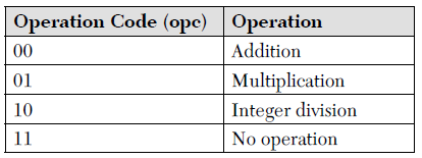
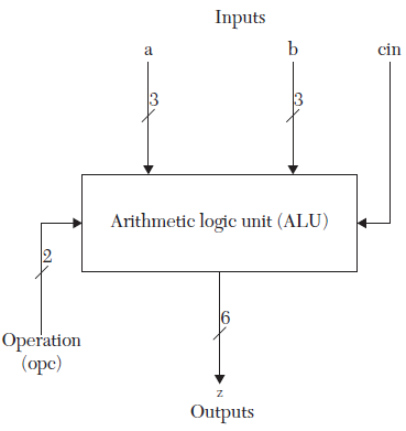
VHDL ALU Description:
--Here the code for a package for user-defined --type and function is written. library ieee; use ieee.std_logic_1164.all; use IEEE.STD_LOGIC_1164.ALL,IEEE.NUMERIC_STD.ALL; package codes_Arithm is type op is (add, mul, divide, none); -- type op is for the operation codes for the ALU. --The operations are: addition, multiplication, --division, and no operation function TO_UNSIGN (b : integer) return unsigned; end; package body codes_Arithm is function TO_UNSIGN (b : integer) return unsigned is --The function converts integers to unsigned. This function --can be omitted if it is included in the vendor’s package; --the vendor’s package, if available, should be attached. variable temp : integer; variable bin : unsigned (5 downto 0); begin temp := b; for j in 0 to 5 loop if (temp MOD 2 = 1) then bin (j) := ‘1’; else bin (j) := ‘0’; end if; temp := temp/2; end loop; return bin; end TO_UNSIGN; end codes_Arithm;
--Now we write the code for the ALU
library IEEE; use IEEE.STD_LOGIC_1164.ALL; use ieee.numeric_std.all; use work.codes_arithm.all; --The above use statement is to set the user- --defined package “codes_arithm.all” visible to this -- module. entity ALU_mixed is port (a, b : in unsigned (2 downto 0); cin : in std_logic; opc : in op; z : out unsigned (5 downto 0)); --opc is of type “op”; type op is defined in the --user-defined package “codes_arithm” end ALU_mixed; architecture ALU_mixed of ALU_mixed is signal c0, c1 : std_logic; signal p, g : unsigned (2 downto 0); signal temp1 : unsigned (5 downto 0); begin --The following is a data flow-description of a 3-bit -- lookahead adder. The sum is stored in the three least -- significant bits of temp1. adder. -- The carry out is stored in temp1(3). g(0) <= a(0) and b(0); g(1) <= a(1) and b(1); g(2) <= a(2) and b(2); p(0) <= a(0) or b(0); p(1) <= a(1) or b(1); p(2) <= a(2) or b(2); c0 <= g(0) or (p(0) and cin); c1 <= g(1) or (p(1) and g(0)) or (p(1) and p(0) and cin); temp1(3) <= g(2) or (p(2) and g(1)) or (p(2) and p(1) and g(0)) or (p(2) and p(1) and p(0) and cin); --temp1(3) is the final carryout of the adders temp1(0) <= (p(0) xor g(0)) xor cin; temp1(1) <= (p(1) xor g(1)) xor c0; temp1(2) <= (p(2) xor g(2)) xor c1; temp1 (5 downto 4) <= «00»; process (a, b, cin, opc, temp1) --The following is a behavioral description for the -- multiplication and division functions of the ALU. variable temp : unsigned (5 downto 0); variable a1, a2, a3 : integer; begin a1 := TO_INTEGER (a); a2 := TO_INTEGER (b); --The predefined function «TO_INTEGER» --converts unsigned to integer. --The function is a member of the VHDL package -- IEEE.numeric. case opc is when mul => a3 := a1 a2; temp := TO_UNSIGN(a3); --The function «TO_UNSIGN» is a user-defined function --written in the user-defined package «codes_arithm.» when divide => a3 := a1 / a2; temp := TO_UNSIGN(a3); when add => temp := temp1; when none => null; end case; z <= temp; end process; end ALU_mixed;
Verilog ALU Description
module ALU_mixed (a, b, cin, opc, z); parameter add = 0; parameter mul = 1; parameter divide = 2; parameter nop = 3; input [2:0] a, b; input cin; input [1:0] opc; output [5:0] z; reg [5:0] z; wire [5:0] temp1; wire [2:0] g, p; wire c0, c1; // The following is data-flow description // for 3-bit lookahead adder assign g[0] = a[0] & b[0]; assign g[1] = a[1] & b[1]; assign g[2] = a[2] & b[2]; assign p[0] = a[0] | b[0]; assign p[1] = a[1] | b[1]; assign p[2] = a[2] | b[2]; assign c0 = g[0] | (p[0] & cin); assign c1 = g[1] | (p[1] & g[0]) | (p[1] & p[0] & cin); assign temp1[3] = g[2] | (p[2] & g[1]) | (p[2] & p[1] & g[0]) | (p[2] & p[1] & p[0] & cin); // temp1[3] is the final carryout of the adders assign temp1[0] = (p[0] ^ g[0]) ^ cin; assign temp1[1] = (p[1] ^ g[1]) ^ c0; assign temp1[2] = (p[2] ^ g[2]) ^ c1; assign temp1[5:4] = 2’b00; //The following is behavioral description always @ (a, b, cin, opc, temp1) begin case (opc) mul : z = a b; add : z = temp1; divide : z = a / b; nop : z = z; endcase end endmodule |
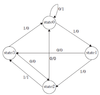
2. Description of a finite sequential-state machine
State machines are very useful tools for designing systems because their
operation can be described in time events or steps.
The state diagram of the machine shows the signals that need to be generated at each step, and it also shows the next step to which the machine has to go. The term states will be used here to refer to steps.
|
VHDL State-Machine Description
library IEEE; use IEEE.STD_LOGIC_1164.all; --First we write a package that includes type “states.” package types is type op is (add, mul, divide, none); type states is (state0, state1, state2, state3); end; -- Now we use the package to write the code for the -- state machine. library IEEE; use IEEE.STD_LOGIC_1164.ALL; use work.types.all; entity state_machine is port (A, clk : in std_logic; pres_st : buffer states; Z : out std_logic); end state_machine; architecture st_behavioral of state_machine is begin FM : process (clk, pres_st, A) variable present : states := state0; begin if (clk = ‘1’ and clk’event) then case pres_st is when state0 => if A =’1’ then present := state1; Z <= ‘0’; else present := state0; Z <= ‘1’; end if; when state1 => if A =’1’ then present := state2; Z <= ‘0’; else present := state3; Z <= ‘0’; end if; when state2 => if A =’1’ then present := state3; Z <= ‘1’; else present := state0; Z <= ‘0’; end if; when state3 => if A =’1’ then present := state0; Z <= ‘0’; else present := state2; Z <= ‘0’; end if; end case; pres_st <= present; end if; end process FM; end st_behavioral;
Verilog State-Machine Description
define state0 2’b00 define state1 2’b01 define state2 2’b10 define state3 2’b11 // We could have declared these states as parameters. module state_machine (A, clk, pres_st, Z); input A, clk; output [1:0] pres_st; output Z; reg Z; reg [1:0] present; reg [1:0] pres_st; initial begin pres_st = 2’b00; end always @ (posedge clk) begin case (pres_st) state0 : begin if (A == 1) begin present = state1; Z = 1’b0; end else begin present = state0; Z = 1’b1; end end state1 : begin if (A == 1) begin present = state2; Z = 1’b0; end else begin present = state3; Z = 1’b0; end end state2 : begin if (A == 1) begin present = state3; Z = 1’b1; end else begin present = state0; Z = 1’b0; end end state3 : begin if (A == 1) begin present = state0; Z = 1’b0; end else begin present = state2; Z = 1’b0; end end endcase pres_st = present; end endmodule |
References:
- HDL Programming (VHDL and Verilog)- Nazeih M.Botros- John Weily India Pvt. Ltd. 2008.
- Fundamentals of HDL – Cyril P.R. Pearson/Sanguin 2010.
- VHDL -Douglas perry-Tata McGraw-Hill
- A Verilog HDL Primer- J.Bhaskar – BS Publications
- Circuit Design with VHDL-Volnei A.Pedroni-PHI


