UNIT 4
Transformers
I Ø transformers and electrostatics
- Types of transformers
Acc to input supply: I phase and  phase
phase
Acc to construction: core and shell type
Acc to 0/P : step up and step down
Construction of transformers (study only for MCQs)
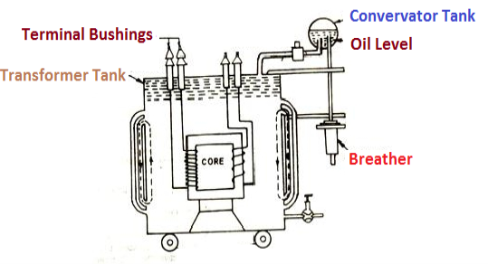
- Laminated steel core
Material used for core is (silicon steel) it is used for its (high permeability) and (low magnetic reluctance)  magnetic field produced is very strong
The core is formed of (stacks of laminated thin steel sheets) which are electrically isolated from each other. They are typically (0.35 to 0.5 mm thick)
We can used 2 ‘L’ shaped sheets or 2  shaped sheets for laminations
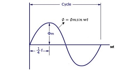
As primary winding excited by the a sinusoidal alternating voltage an alternating current flows in the winding producing an alternating varying flux Ø
Ø = Øm sin wt
As per Faradays Law of Electromagnetic Induction emf E1 is induced
E1 = N1 
E1 = N1  (Ø Sin wt)
= - N1 Øm w Cos wt
Sin (90-wt)
= - Sin (wt-90)
 E1 = N1 Øm w Sin (wt-90)
 w =
w = 
 E1 =
E1 =  N1 Ø m Sin (wt-90)
Max value of E1 = E max
Is when Sin (wt-90) =  1
1
E1 max =  N1 Ø m
Hence rms value of induced EMF in primary winding
E1 rms =  =
= 
 E1 = 4.44 F Ø m N1
 Similarly RMS value of induced EMF in secondary wdg Is
E2 = 4.44 F Ø m N2
- Losses in a Transformer
There are 2 types of losses occurring in a transformer
A) 1. Core loss or Iron loss
B) 2. Copper loss
- Core losses:
- This loss is due to the reversal of flux
- The flux set up in the core is dependent on the i/p supply
 as the i/p supply is constant in magnitude
  the flux set up will be constant and
  core losses are also constant.
 - Core losses are voltage dependent loss they can be subdivided in 2
1 Hysteresis loss
2 reedy current loss
- Hysteresis loss : The iron loss occurring in the core of T/F due to the Hysteresis curve of the magnetic material used for core is called as Hysteresis loss.
Hysteresis curve is the curve as loop which shows the properly of magnetic material to lag the flux density B behind the field Intensely H
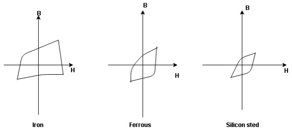
Above is the 3 different loops (Hysteresis of 3 diff. Materials)
 the selection of magnetic material for the construction of core depends upon Hysteresis loop of that material having tall and narrow Hysteresis loop is selected for the T/F core
 silicon Steel
Hysteresis loss depends on fold factor
PH = KH. Bm1.67 F  V – watts
Where KH = constant (Hyst)
Bm = max Flux density
F = Frequency
 = Volume of core.
2. Reedy current loss :
This loss is due to the flow of reedy (circular) current in the core caused by induced emf in core
PE = Ke Bm2 f2 t2 v – watts
Where
Ke = reedy current const.
t = thickness of core
It can be reduced by using stacks of laminations instead of solid core
B] Copper loss : PCU
The Copper loss is due to resistance of the primary and secondary winding
It is load dependent / current dependent loss
As load on a transformer is variable (changing)  current changes
  copper loss is a variable loss
Primary secondary
Total C is loss = I12 R12 + I22 R22
Copper loss depends upon load on T/F and is proportional to square of load current or KVA rating of transformer
 PCU
PCU  2
2  (KVA)2
F.L = full load
 PCU (at half load) =
  2 PCu F.L
= (0.5)2 PCU F.L.
Or PCu ( load) = (
 )2 PCu F.L
IDEAL TRANSFORMER
An ideal transformer is one that has
- No winding resistance
- No leakage flux i.e., the same flux links both the windings
- No iron losses (i.e., eddy current and hysteresis losses) in the core
Although an ideal transformer cannot be physically realized, yet its study provides a very powerful tool in the analysis of a practical transformer. In fact, practical transformers have properties that approach very close to an ideal transformer.
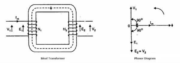
Consider an ideal transformer on no load i.e., the secondary is open-circuited as shown in the figure. Under such conditions, the primary is simply a coil of pure inductance.
When an alternating voltage V₁ is applied to the primary, it draws a small magnetizing current Iₘ which lags behind the applied voltage by 90°. This alternating current Iₘ produces an alternating flux ϕ which is proportional to and in phase with it.
The alternating flux ϕ links both the windings and induces e.m.f. E₁ in the primary and e.m.f. E₂ in the secondary. The primary e.m.f. E₁ is, at every instant, equal to and in opposition to V₁ (Lenz’s law). Both e.m.f.s E₁, and E₂ lag behind flux ϕ by 90°. However, their magnitudes depend upon the number of primary and secondary turns.
Phasor Diagram of Ideal Transformer
The phasor diagram of an ideal transformer on no load is also shown above. Since flux ϕ is common to both the windings, it has been taken as the reference phasor.
The primary e.m.f. E₁ and secondary e.m.f. E₂ lag behind the flux ϕ by 90°.
Note that E₁ and E₂ are in phase. But E₁ is equal to V₁ and 180° out of phase with it.
Practical Transformer
A practical transformer differs from the ideal transformer in many respects. The practical transformer has,
- Iron losses,
- Winding resistances and,
- Magnetic leakage, giving rise to leakage reactance.
1. Iron Losses
Since the iron core is subjected to alternating flux, there occurs eddy current and hysteresis loss in it. These two losses together are known as iron losses or core losses.
The iron losses depend upon the supply frequency, the maximum flux density in the core, volume of the core, etc.
It may be noted that the magnitude of iron losses is quite small in a practical transformer.
2. Winding resistances
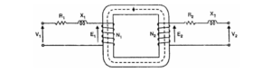
Since the windings consist of copper conductors, it immediately follows that both primary and secondary will have winding resistance. The primary resistance R₁ and secondary resistance R₂ act in series with the respective windings as shown in the figure.
When current flows through the windings, there will be power loss as well as a loss in voltage due to IR drop. This will affect the power factor and E₁ will be less than V₁ while V₂ will be less than E₂.
3. Leakage reactances
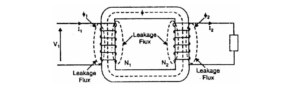
Both primary and secondary currents produce flux. The flux ϕ which links both the windings is the useful flux and is called mutual flux.
However, the primary current would produce some flux ϕ which would not link the secondary winding. Similarly, the secondary current would produce some flux ϕ that would not link the primary winding.
The flux such as ϕ₁ or ϕ₂ which links only one winding is called leakage flux. The leakage flux paths are mainly through the air. The effect of these leakage fluxes would be the same as though inductive reactance were connected in series with each winding of the transformer that had no leakage flux as shown in the figure.
In other words, the effect of primary leakage flux ϕ₁ is to introduce an inductive reactance X₁ in series with the primary winding as shown. Similarly, the secondary leakage flux ϕ₂ introduces an inductive reactance X₂ in series with the secondary winding.
There will be no power loss due to leakage reactance. However, the presence of leakage reactance in the windings changes the power factor as well as there is voltage loss due to IX drop.
Note.
Although leakage flux in a transformer is quite small (about 5% of ϕ) compared to the mutual flux ϕ, yet it cannot be ignored.
It is because leakage flux paths are through the air of high reluctance and hence require considerable e.m.f. It may be noted that energy is conveyed from the primary winding to the secondary winding by mutual flux f which links both the windings.
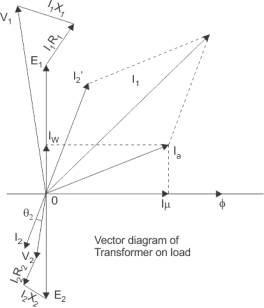
For drawing equivalent circuit of transformer referred to primary, first establish general equivalent circuit of transformer then, modify it for referring from primary side. The vector diagram of transformer which is shown in the figure.
Let us consider the transformation ratio be,
K = N1/N2 = E1/E2
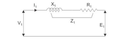
In the figure the applied voltage to the primary is V1 and voltage across the primary winding is E1. Total current supplied to primary is I1. So, the voltage V1 applied to the primary is partly dropped by
I1Z1 or I1R1 + j.I1X1 before it appears across primary winding.
The voltage appeared across winding is countered by primary induced emf E1.
So, voltage equation of this portion of the transformer can be written as,
V1 – (I1 R1 + j I1 X1 ) = E1
The equivalent circuit for the equation can be drawn as
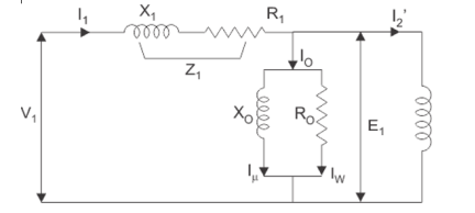
From the vector diagram it is found that the total primary current I1 has two components, one is no – load component Io and the other is load component I2′.
As this primary current has two components or branches, so there must be a parallel path with primary winding of transformer.
This parallel path of current is known as excitation branch of equivalent circuit of transformer. The resistive and reactive branches of the excitation circuit can be represented as
R0 = E1/ Iw and Xo = E1/ I μ
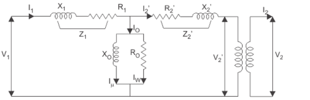
The load component I2′ flows through the primary winding of transformer and induced voltage across the winding is E1 as shown in the figure right. This induced voltage E1 transforms to secondary and it is E2 and load component of primary current I2′ is transformed to secondary as secondary current I2. Current of secondary is I2. So, the voltage E2 across secondary winding is partly dropped by
I2Z2 or I2R2 + j.I2X2 before it appears across load.
The load voltage is V2.
The complete equivalent circuit of transformer is shown below.
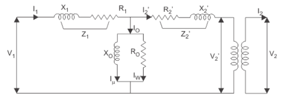
Now if we see the voltage drop in secondary from primary side, then it would be ′K′ times greater and would be written as K.Z2.I2.
Again I2′.N1 = I2.N2
I2 = I2’ N1/N2
I2 = K I’2
Therefore,
K Z 2 I 2 = K Z 2 K I 2’ = K 2 Z 2 I 2 ‘
From above equation, secondary impedance of transformer referred to primary is,
Z 2’ = K 2 Z 2
Hence R2’ = K2 R2 and X2 = K 2 X 2
So, the complete equivalent circuit of transformer referred to primary is shown in the
Figure below.
Open circuit test:
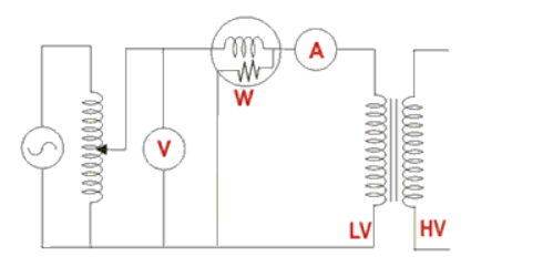
The connection diagram for open circuit test on transformer is shown in the figure. A voltmeter, wattmeter, and an ammeter are connected in LV side of the transformer as shown. The voltage at rated frequency is applied to that LV side with the help of a variac of variable ratio auto transformer.
The HV side of the transformer is kept open. Now with the help of variac, applied voltage gets slowly increased until the voltmeter gives reading equal to the rated voltage of the LV side. After reaching rated LV side voltage, we record all the three instruments reading (Voltmeter, Ammeter and Wattmeter readings).
The ammeter reading gives the no load current Ie. As no load current Ie is quite small compared to rated current of the transformer, the voltage drops due to this current that can be taken as negligible.
Since voltmeter reading V1 can be considered equal to the secondary induced voltage of the transformer, wattmeter reading indicates the input power during the test.
As the transformer is open circuited, there is no output, hence the input power here consists of core losses in transformer and copper loss in transformer during no load condition. The no-load current in the transformer is quite small compared to the full load current so, we can neglect the copper loss due to the no-load current.
Hence, can take the wattmeter reading as equal to the core losses in the transformer.
Let us consider wattmeter reading is Po.
Po = V1 2 / Rm
Where Rm is the shunt branch resistance of the transformer.
If Zm is the shunt branch resistance of the transformer
Zm = V1/ Ie
Therefore, if shunt branch reactance of transformer is Xm,
Then (1/Xm ) 2 = (1/Zm) 2 – (1/Rm ) 2
These values are referred to the LV side of the transformer due to the tests being conducted on the LV side of transformer.


