UNIT 3
Generation of Three-Phase Voltages
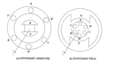
The three -phase voltage can be generated in stationary armature with rotating field structure or in rotating armature with a stationary field as shown in figure.
Single phase voltages and currents are generated by single phase generators as shown in Figure. The armature of such a generator has only one winding, or one set of coils. In a two-phase generator the armature has two distinct windings, or two sets of coils that are displaced 90° apart, so that the generated voltages in the two phases have 90 degrees phase displacement as shown in Fig. b.
For Three Phase Voltage are generated in three separate but identical sets of windings or coils that are displaced by 120 electrical degrees in the armature, so that the voltages generated in them are 120° apart in time phase. This arrangement is shown in Fig. (c). Here RR’ constitutes one coil (R-phase); YY’ another coil (Y-phase), and BB’ constitutes the third phase (B-phase). The field magnets are assumed in clockwise rotation.
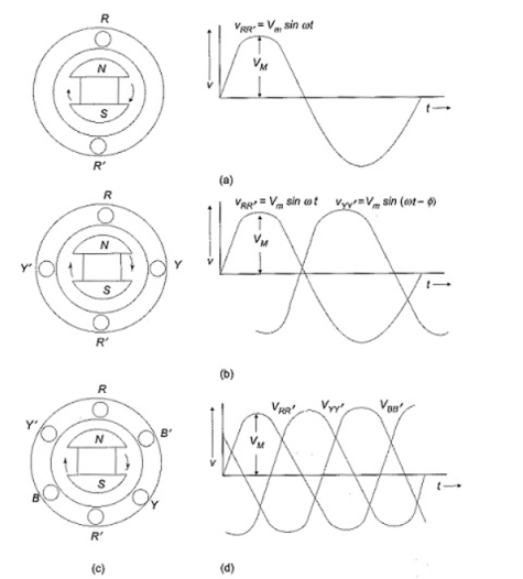
The voltages generated by a three-phase alternator is shown in Fig. (d). The Three Phase voltage are of the same magnitude and frequency; but are displaced from one another by 120°. Assuming the voltages to be sinusoidal, we can write the equations for the instantaneous values of the voltages of the three phases. Counting the time from the instant when the voltage in phase R is zero. The equations are
v RR’ = Vm sinwt
v YY’ = Vm sin (wt -120 o )
v BB’ = Vm sin(wt -240 o )
At any given instant, the algebraic sum of the three voltages must be zero.
Phase Sequence:
Here the sequence of voltages in the three phases are in the order υRR′ – υYY′ – υBB′, and they undergo changes one after the other in the mentioned order. This is called the phase sequence. This sequence depends on the rotation of the field. If the field system is rotated in anticlockwise direction, then the sequence of the voltages in the three-phases are in the order υRR′ – υBB′ – υYY′. Now the equations can be written as
v RR’ = Vm sinwt
v BB’ = Vm sin (wt -120)
v YY’ = Vm sin(wt – 240)
Drive
- Relation between line value and phase value of voltage and current for a balance (
 ) delta connected inductive load
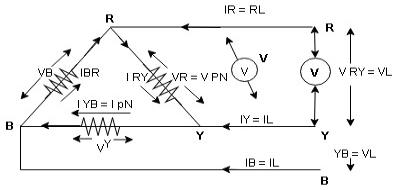
Consider a 3 Ø balance delta connected inductive load
- Line values
Line voltage = VRY = VYB = VBR = VL
Line current = IR = IY = IB = IL
Phase value
Phase voltage = VRN = VYN = VBN = Vph
Phase current = VRN = VYN = VBN = Vph
- Since for a balance delta connected load the voltage measured in line and phase is same because their measuring points are same
 for balance delta connected load VL = Vph
 VRV = VYB = VBR = VR = VY = VB = VL = VPh
- Since the line current differ from phase current we can relate the line and phase values of current as follows
- Apply KCL at node R
IR + IRY= IRY
 IR = IRY - IRY … …. ①

Line phase
Similarly apply KCL at node Y
IY + IYB = IRY … …. ②
Apply KCL at node B
IB + IBR = IYB … ….③
PPh = VPh IPh Cos Ø
For 3 Ø total power is
PT= 3 VPh IPh Cos Ø …….①
For star
VL and IL = IPh (replace in ①)
 PT = 3
  IL Cos Ø
 PT = 3
  VL IL Cos Ø – watts
For delta
VL = VPh and IL =  (replace in ①)
PT = 3VL
= 3VL  Cos Ø
Cos Ø
 PT
PT VL IL Cos Ø – watts
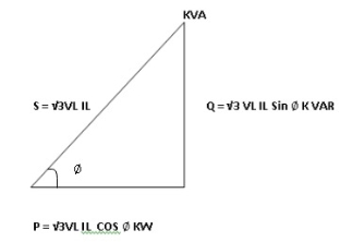
Total average power
P =  VL IL Cos Ø – for ʎ and
  load
load
K (watts)
Total reactive power
Q =  VL IL Sin Ø – for star
  delta load
K (VAR)
Total Apparent power
S =  VL IL – for star
  delta load
K (VA)
- Power triangle
- Relation between power
In star and power in delta
Consider a star connected balance load with per phase impedance ZPh
We know that for
VL = VPh andVL =  VPh
VPh
Now IPh = 
 VL = =
And VPh = 
 IL =
IL =  ……①
……①
Pʎ =  VL IL Cos Ø ……②
Replacing ① in ② value of IL
 Pʎ =
Pʎ =  VL IL
VL IL  Cos Ø
Cos Ø
 Pʎ =
Pʎ =  ….A
….A
- Now for delta
IPh = 
 IPh = =
And IL =  IPh
IPh
 IL =
IL =  X
X  …..①
…..①
P =
=  VL IL Cos Ø ……②
Replacing ② in ① value of IL
P =
=  Cos Ø
Cos Ø
 P
P =
=  …..B
…..B

Pʎ from …A
 …..C
…..C
 =
=  P
P
We can conclude that power in delta is 3 time power in star from …C
Or
Power in star is  time power in delta from ….D
- Step to solve numerical
- Calculate VPh from the given value of VL by relation
For star VPh = 
For delta VPh = VL
2. Calculate IPh using formula
IPh = 
3. Calculate IL using relation
IL = IPh - for star
IL =  IPh - for delta
4. Calculate P by formula (active power)
P =  VL IL Cos Ø – watts
5. Calculate Q by formula (reactive power)
Q =  VL IL Sin Ø – VAR
6. Calculate S by formula (Apparent power)
S =  VL IL– VA
Wattmeter method).
Two Wattmeter Method can be employed to measure the power in a 3 phase, three-wire star or delta connected the balanced or unbalanced load.
In two wattmeter method, the current coils of the wattmeter are connected with any two lines, say R and Y and the potential coil of each wattmeter is joined on the same line, the third line that is B as shown below in
The total instantaneous power absorbed by the three loads Z1, Z2 and Z3, is equal to the sum of the powers measured by the two -watt meters, W1 and W2.
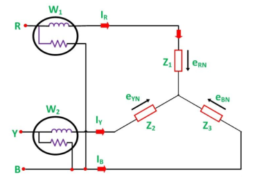
Measurement of Power by Two Wattmeter using star connection.
Considering the above figure in which Two Wattmeter W1 and W2 are connected, the instantaneous current through the current coil of Wattmeter, W1 is given by the equation shown below:
W1 = i R
The instantaneous potential difference across the potential coil of Wattmeter, W1 is given as:
W1 = e RN – e BN
The Instantaneous power measured by Wattmeter W1 is
W1 = i R (e RN – e BN) ---------------------------(1)
The instantaneous current through the current coil of Wattmeter, W2 is given by the equation:
W2 = i Y (eYN – e BN) ----------------------------------------------------(2)
The instantaneous potential difference across the potential coil of Wattmeter, W2 is given as:
W2 = e YN – e BN --------------------------------------------(3)
Instantaneous power measured by Wattmeter, W2 is
W2 = iY ( eYN – e BN)
Therefore, the total power measured by the two- watt meters W1 and W2 is obtained by adding the equation (1) and (2).
W1 + W2 = i R (e RN – e BN) + iY ( eYN – e BN)
W1 + W2 = i R e RN + iY eYN - e BN ( i R + i Y) or
W1 + W2 = i R e RN + iY eYN + i B e BN ( that is i R + i Y + i B =0)
W1 + W2 = P
Where, P – the total power absorbed in the three loads at any instant.
Measurement of Power by Two Wattmeter Method in Delta Connection
Considering the delta connected circuit shown in the figure below:
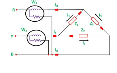
The instantaneous current through the coil of the wattmeter, W1 is given by the equation:
W 1 = i R = i 1 – i 3
Instantaneous power measured by the Wattmeter, W1 will be:
W 1 = e RB
Therefore, the instantaneous power measured by the wattmeter, W1 will be given as:
W 1 = eRB( i 1 – i 3) …………………(3)
The instantaneous current through the current coil of the Wattmeter, W2 is given as:
W2 = i Y = i2 – i1
The instantaneous current through current coil of the Wattmeter W2 is given as :
W 2 = i Y = i 2 – i 1
The instanteneous potential difference across the potential coil of wattmeter, W 2
W2 = e YB
Therefore the instantaneous power measured by Wattmeter W2 will be:
W2 = e YB (i2 – i1 ) ……………………(4)
Hence, to obtain the total power measured by the two wattmeter the two equations, i.e. equation (3) and (4) has to be added.
Where P is the total power absorbed in the three loads at any instant.
W1 + W2 = e RB ( i1 – i3) + e YB ( i2 – i1)
W1 + W2 = i 1 e RB + i 1 e YB – i 3 e RB – i1 e YB
W 1 + W 2 = i 2 e YB + i 3 e BR – i1 ( eYB + e BR) ( that is – e RB = e RB )
W 1 + W 2 = i 1 e RY + i 2 e YB + i 3 e BR
W 1 + W 2 = P
The power measured by the Two Wattmeter at any instant is the instantaneous power absorbed by the three loads connected in three phases. In fact, this power is the average power drawn by the load since the Wattmeter reads the average power because of the inertia of their moving system.


