UNIT 2
AC Circuits
The voltage which changes polarity at regular interval of time is known as the alternating voltage. The one complete cycle of an alternating quantity consists two half cycles. And the direction of a half cycle changes after every particular interval of time. The machine which generates the alternating voltage is known as the alternator.
The alternating voltage is generated in two ways.
- By rotating the coil inside the uniform magnetic field at constant speed
- By rotating the magnetic field around the stationary coil at the constant speed.
In small AC generators, the coil rotates between the magnetic field, whereas in large ac generator the magnetic field rotates around the coil because of some economical consideration.
Process of generating alternating voltage:
Consider the stationary coil places inside the uniform magnetic field. The load is connected across the coil with the help of brushes and the slip rings. When the coil rotates in the anticlockwise direction at constant angular velocity ω the electromotive force induces in the coil. The cross-sectional view of the coil at the different position is shown in the figure below.
The magnitude of the emf induced in the coil depends on the rate of the flux cut by the conductor. The figure below shows that the no current induces in the coil when they are parallel to the magnetic line of forces. i.e., at the position (1), (2) and (3). And the total flux cut by the conductor becomes zero.
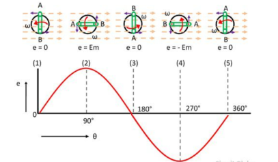
The magnitude of the induces emf becomes maximum when the conductor becomes perpendicular to the magnetic line of force. The conductor cuts the maximum flux at this position.
The direction of the emf induces in the conductor is determined by Fleming’s right-hand rule. When the coil is at position (2) the emf induces in the outward direction of the conductor whereas at position (4) the direction of the inducing emf becomes inward.
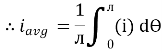
Average Value:
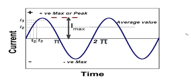
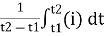
The arithmetic mean of all the value over complete one cycle is called as average value
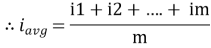
 =
= 
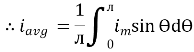
For the derivation we are considering only hall cycle.
Thus  varies from 0 to ᴫ
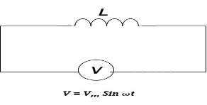
i = Im Sin
Solving
We get

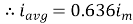
Similarly, Vavg=
The average value of sinusoid ally varying alternating current is 0.636 times maximum value of alternating current.
RMS value: Root mean square value
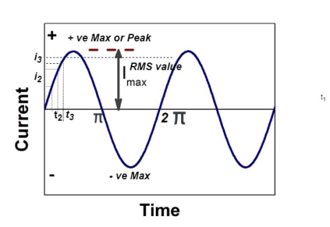
The RMS value of AC current is equal to the steady state DC current that required to produce the same amount of heat produced by ac current provided that resistance and time for which these currents flows are identical.
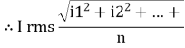
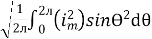
I rms = 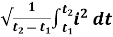
Direction for RMS value:
Instantaneous current equation is given by
i = Im Sin 
But 
I rms = 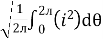
= 
=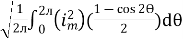
=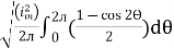
Solving
=
=
Similar we can derive
V rms=  or 0.707 Vm
 the RMS value of sinusoidally alternating current is 0.707 times the maximum value of alternating current.
Phase: It is angle made by the (conductor) phases with respect to reference axis. It is denoted by Ø
Phase difference: The difference between the phase of 2 alternating quantities is called as phase difference there are
- Positive phase difference + Ø
- Negative phase difference – Ø
- Zero phase difference Ø = 0
We consider always 2 ac quantities. One is voltage and current.
Now as voltage is independent quality i.e. not dependent on load.
 It is always considered as reference quantity
  v=V m sin (w t)
→ Current is load dependent quantity.
Therefore it creates phase difference according to load.  current equation can be written as 𝑖=Im sin
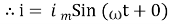
Case1. Zero phase difference (Ø=0)
Equations
V=Vm sin w t – Reference
𝑖 = I m sin (w t + 0)  Ø = 0
Ø = 0
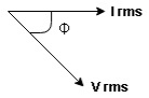
Case2 +v e phase difference or Leading phase difference (Ø = + v e)
Equation
V= Vm sin w t – Reference
𝑖 = Im sin (w t + Ø)
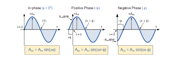
Case 3 - v e phase difference or Lagging phase difference (Ø = -v e )
Equation v = vm sin w t – Reference
= Im sin (w t - Ø)
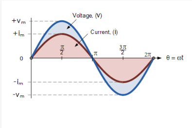
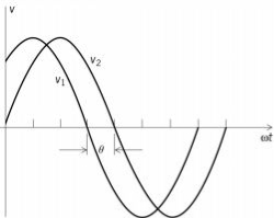
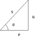
Two AC signals current and voltage will lead one another depending upon what type of component/load used like inductor OR capacitor
The difference in angle between these two signals is known as Phase Difference. The Phase difference is indicated by an angle theta OR omega
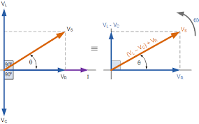
Now if Two Voltage OR current sources are connected to a circuit and if these two are having a phase difference, then the net effect of these two sources with phase difference will have a sum of effect , which is Not direct sum but a phasor sum that depends upon the phase angle as shown below
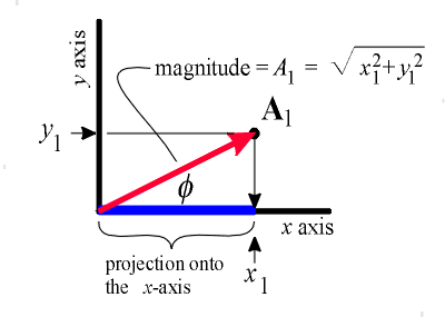
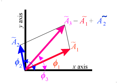
It is actually a Vector Addition. Since Vector quantities have directions it will be lesser than normal additions
3 Basic element of AC circuit.
1] Resistance
2] Inductance
3] Capacitance
Each element produces opposition to the flow of AC supply in forward manner.
Reactance
- Inductive Reactance (XL)
It is opposition to the flow of an AC current offered by inductor.
XL = ω L But ω = 2 ᴫ F
 XL = 2 ᴫ F L
It is measured in ohm
 XL∝FInductor blocks AC supply and passes dc supply zero
2. Capacitive Reactance (Xc)
It is opposition to the flow of ac current offered by capacitor
Xc = 
Measured in ohm
 Capacitor offers infinite opposition to dc supply
Impedance (Z)
The ac circuit is to always pure R pure L and pure C it well attains the combination of these elements. “The combination of R1 XL and XC is defined and called as impedance represented as
Z = R +i X
Ø = 0
 only magnitude
R = Resistance, i = denoted complex variable, X =Reactance XL or Xc
Polar Form
Z =  L I
L I
Where  =
=
 Measured in ohm
Power factor (P.F.)
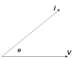
It is the cosine of angle between voltage and current
If Ɵis –ve or lagging (I lags V) then lagging P.F.
If Ɵ is +ve or leading (I leads V) then leading P.F.
If Ɵ is 0 or in phase (I and V in phase) then unity P.F.
Ac circuit containing pure resisting
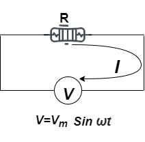
Consider Circuit Consisting pure resistance connected across ac voltage source
V = Vm Sin ωt ①
According to ohm’s law i =  =
= 
But Im = 
 ②
②
Phases diagram
From ① and ② phase or represents RMD value.
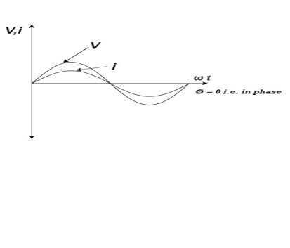
Power P = V. i
Equation P = Vm sin ω t Im sin ω t
P = Vm Im Sin2 ω t
P =  -
- 

Constant fluctuating power if we integrate it becomes zero

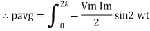
Average power
Pavg = 
Pavg = 
Pavg = Vrms Irms
Power ware form [Resultant]
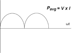
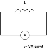
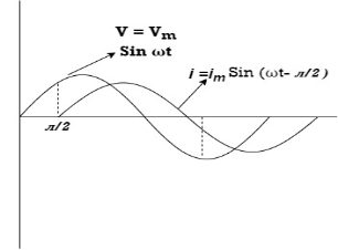
Ac circuit containing pure Inductors
Consider pure Inductor (L) is connected across alternating voltage. Source
V = Vm Sin ωt
When an alternating current flow through inductance it set ups alternating magnetic flux around the inductor.
This changing the flux links the coil and self-induced emf is produced
According to faradays Law of E M I
e = 
At all instant applied voltage V is equal and opposite to self-induced emf [ lenz’s law]
V = -e
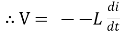 =
= 
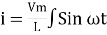
But V = Vm Sin ωt
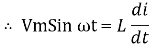
 dt
dt
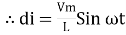
Taking integrating on both sides
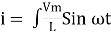 dt
dt
 dt
dt
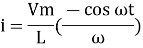
 (-cos
(-cos  )
)
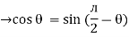
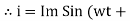
But sin (– ) = sin (+
 )
)
 sin (
sin ( -
-  /2)
/2)
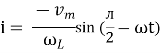
And Im= 
 /2)
/2)
 /2
/2
= -ve
= lagging
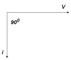
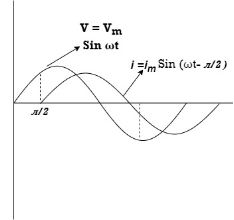
= I lag v by 900

Phasor:
Power P = Ѵ. I
= Vm sin wt Im sin (wt  /2)
/2)
= Vm Im Sin wt Sin (wt –  /s)
/s)
 ①
①
And
Sin (wt -  /s) = - cos wt ②
Sin (wt –  ) = - cos
 sin 2 wt from ① and ②
The average value of sin curve over a complete cycle is always zero
 Pavg = 0
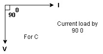
Ac circuit containing pure capacitors:
Consider pure capacitor C is connected across alternating voltage source
Ѵ = Ѵm Sin wt
Current is passing through capacitor the instantaneous charge ɡ produced on the plate of capacitor
ɡ = C Ѵ
ɡ = c Vm sin wt
The current is rate of flow of charge

i= (cvm sin wt)
i = c Vm w cos wt
Then rearranging the above eqth.
i =  cos wt

 = sin (wt +
  X/2)
X/2)
i =  sin (wt + X/2)
But 
 X/2)
X/2)

= leading
= I leads V by 900
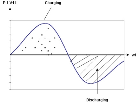
Waveform :
Phase
Power P= Ѵ. i
= [Vm sinwt] [ Im sin (wt + X/2)]
= Vm Im Sin wt Sin (wt + X/2)]
 (cos wt)
 to charging power waveform [resultant].
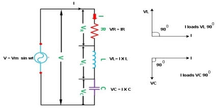
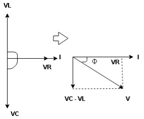
Series R-L Circuit
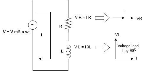
Consider a series R-L circuit connected across voltage source V= Vm sin wt
As some I is the current flowing through the resistor and inductor due do this current voltage drops arcos R and L R  VR = IR and L
  VL = I X L
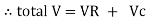
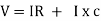
 Total V = VR + VL
V = IR + I X L  V = I [R + X L]


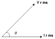
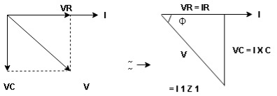
Take current as the reference phasor : 1) for resistor current is in phase with voltage 2) for Inductor voltage leads current or current lags voltage by 90 0.
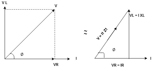
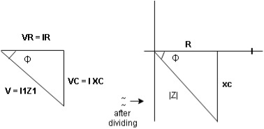
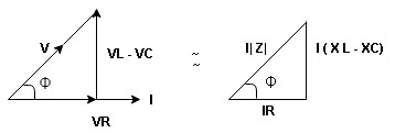
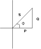
For voltage triangle
Ø is power factor angle between current and resultant voltage V and
V = 
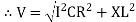
V = 

Where Z = Impedance of circuit and its value is  =
= 
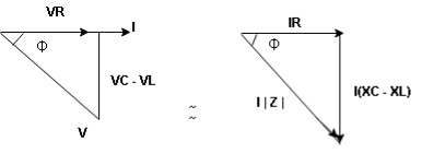
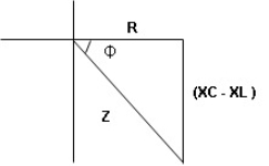
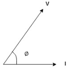
Impedance Triangle
Divide voltage triangle by I
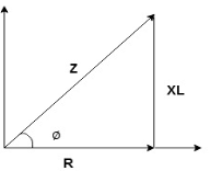
Rectangular form of Z = R+ixL
And polar from of Z =  L +
L + 
(+ j X L +  because it is in first quadrant )
Where  =
= 
 + Tan -1
Current Equation :
From the voltage triangle we can sec. That voltage is leading current by  or current is legging resultant voltage by
Or i =  =
=  [ current angles - Ø )
Resultant Phasor Diagram from Voltage and current eqth.
Wave form

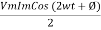
Power equation
P = V .I.
P = Vm Sin wt Im Sin wt – Ø
P = Vm Im (Sin wt) Sin (wt – Ø)
P =  (Cos Ø) - Cos (2wt – Ø)
Since 2 sin A Sin B = Cos (A-B) – Cos (A+B)
P =  Cos Ø -
  Cos (2wt – Ø)

①②
Average Power
Pang =  Cos Ø
Cos Ø
Since ② term become zero because Integration of cosine come from 0 to 2ƛ
 pang = Vrms Irms cos Ø watts.
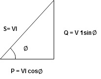
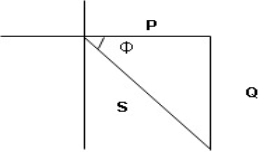
Power Triangle :
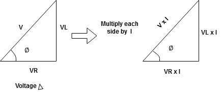
From 
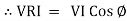
VI = VRI + VLI B
Now cos Ø in  A =
A = 
 ①
①
Similarly Sin  =
= 


Apparent Power Average or true Reactive or useless power
Or real or active
-Unit (VI) Unit (Watts) C/W (VAR) denoted by (Ø)
Denoted by [S] denoted by [P]
Power  for R L ekt.
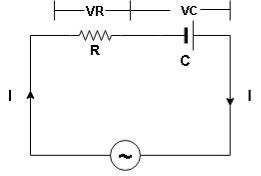
Series R-C circuit
V = Vm sin wt
VR

 I
I
- Consider a series R – C circuit in which resistor R is connected in series with capacitor C across a ac voltage so use V = VM Sin wt (voltage equation).
- Assume Current I is flowing through
R and C  voltage drops across.
R and C  R
R  VR = IR
And C  Vc = I
 c
c

 V =
V =  lZl
lZl
Voltage triangle : take current as the reference phasor 1) for resistor current is in phase with voltage 2) for capacitor current leads voltage or voltage lags behind current by 900
Where Ø is power factor angle between current and voltage (resultant) V
And from voltage
V = 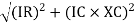
V = 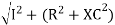
V = 
V =  lZl
lZl
Where Z = impedance of circuit and its value is lZl = 
Impendence triangle :
Divide voltage  by
by  as shown
Rectangular from of Z = R - jXc
Polar from of Z = lZl L - Ø
( - Ø and –jXc because it is in fourth quadrant ) where
LZl = 
And Ø = tan -1 
Current equation :
From voltage triangle we can see that voltage is lagging current by Ø or current is leading voltage by Ø
 i = IM Sin (wt + Ø) since Ø is +ve
Or i =  for RC
 LØ [ resultant current angle is + Ø]
Resultant phasor diagram from voltage and current equation
Resultant wave form :
Power Equation :
P = V. I
P = Vm sin wt. Im Sin (wt + Ø)
= Vm Im sin wt sin (wt + Ø)
2 Sin A Sin B = Cos (A-B) – Cos (A+B)
 -
- 
Average power
Pang =  Cos Ø
Cos Ø
Since 2 terms integration of cosine wave from 0 to 2ƛ become zero
 2 terms become zero
 pang = Vrms Irms Cos Ø
Power triangle RC Circuit:
R-L-C series circuit
Consider ac voltage source V = Vm sin wt connected across combination of R L and C. When I flowing in the circuit voltage drops across each component as shown below.
VR = IR, VL = I  L, VC = I
  C
C
- According to the values of Inductive and Capacitive Reactance I e XL and XC decides the behaviour of R-L-C series circuit according to following conditions
① XL> XC, ② XC> XL, ③ XL = XC
① XL > XC: Since we have assumed XL> XC
 Voltage drop across XL> than XC
 VL> VC A
- Voltage triangle considering condition A

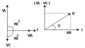
VL and VC are 180 0 out of phase .
Therefore cancel out each other
 Resultant voltage triangle
Now V = VR + VL + VC c phasor sum and VL and VC are directly in phase opposition and VL
 VC
VC their resultant is (VL - VC).
From voltage triangle
V = 
 V =
V = 
 V = I
V = I 

Impendence  : divide voltage
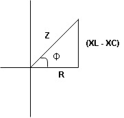
Rectangular form Z = R + j (XL – XC)
Polor form Z =  l + Ø B
Where  =
= 
And Ø = tan-1 
- Voltage equation : V = Vm Sin wt
- Current equation
i =  from B
i =  L-Ø C
L-Ø C
As VL VC the circuit is mostly inductive and
  I lags behind V by angle Ø
 Since i =
  L-Ø
L-Ø
 i = Im Sin (wt – Ø) from c
- XC
 XL :Since we have assured XC
  XL
XL
 the voltage drops across XC
  than XL
 XC
XC  XL (A)
 voltage triangle considering condition (A)
 Resultant Voltage
Now V = VR + VL + VC  phases sum and VL and VC are directly in phase opposition and VC
 VL
VL  their resultant is (VC – VL)
From voltage 
V = 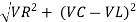
V = 
 V =
V = 
 V =
V = 

 Impedance
  : Divide voltage
- Rectangular form : Z + R – j (XC – XL) – 4th qurd
Polar form : Z =  L -
L -
Where 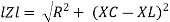
And Ø = tan-1 – 
- Voltage equation : V = Vm Sin wt
- Current equation : i =
 from B
 - i =
 L+Ø C
L+Ø C
As VC  the circuit is mostly capacitive and
  leads voltage by angle Ø
Since i =  L + Ø
L + Ø
 Sin (wt – Ø) from C
- Power
 :
:
- XL= XC (resonance condition):
ɡȴ XL= XC then VL= VC and they are 1800 out of phase with each other  they will cancel out each other and their resultant will have zero value.
Hence resultant V = VR and it will be in phase with I as shown in below phasor diagram.
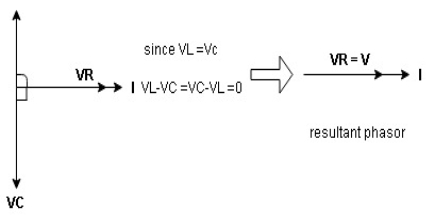
From above resultant phasor diagram
V =VR + IR
Or V = I  lZl
lZl
Because lZl + R
Thus Impedance Z is purely resistive for XL = XC and circuit current will be in phase with source voltage.

 Since VR= V Øis zero when XL = XC
  power is unity
Ie pang = Vrms I rms cos Ø = 1 cos o = 1
Maximum power will be transferred by condition. XL = XC
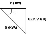
- Apparent power (S) : it is defined as product of rms value of voltage (V) and current (I) or it is the total power / max power
S = V 
 Unit - volt – Ampere (VA)
In kilo – K. V. A.
2. Real power / true power / active power / useful power : [P] it is defined as the product of rms value active component or it is the average power or actual power consumed by the resistive part (R) in the given combinational circuit
It is measured in watts
P = VI Cos Ø watts /km where Ø is the power factor angle
3. Reactive power / Imaginary / useless power [Q]
It is defined as the product of voltage current and sine of angle between V and

Volt Amp Relative
 Unit – V A R
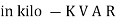
 Power triangle
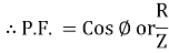
- As we know power factor is cosine of angle between voltage and current
i e P.F. = Cos 
In other words also we can derive it from impedance triangle
Now consider Impedance triangle in R – L- ckt.
From  now Cos
  = power factor =
 power factor = Cos
  or
or 
Admittance is defined as reciprocal of the impedance (Z)
It is denoted by Y and its unit Siemens (S)
 Admittance Y =
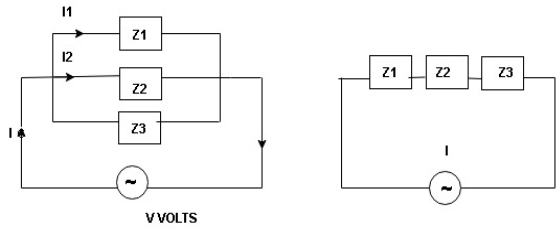
I = I1 + I2 + I3
 =
=  +
+  +
+ 
 =
=  +
+  +
+ 
Y = Y1 + Y2 + Y3
Rationalize the expression of Y as follows
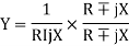
Y = 
But Z2 = R2 + X2
 Y =
Y = 
Let  + G + conductance
 = B = susceptance
 Y = G
Y = G  jB
jB
Conductance (G) : it is defined as the ratio of resistance R and the squared impedance (Z2) and it is measured in Siemens or mho 
G = 
Theoretically G = reciprocal od resistance.
Susceptance (B) :it is defined as the ratio of reactance X and the squared impedance (Z2) or mho 
B = 
Theoretically B = reciprocal od resistance.
Resonance in series RLC circuits
Definition: it is defined as the phenomenon which takes place in the series or parallel R-L-C circuit which leads to unity power factor
Voltage and current in R – L - C ckt. Are in phase with each other
Resonance is used in many communicate circuit such as radio receiver.
Resonance in series RLC series resonance in parallel RLC anti resonance / parallel resonance.
- Condition for resonance XL = XC
- Resonant frequency (Fr) : for given values of R-L-C the inductive reactance XL become exactly aqual to the capacitive reactance Xc only at one particular frequency. This frequency is called as resonant frequency and denoted by (fr)
- Expression for resonant frequency(fr) : we know thet XL = 2ƛ FL - Inductive reactance
Xc =  - capacitive reactance
At a particular frequency ȴ = fr, the Inductive and capacitive reactance are exactly equal
 XL = XC ……at ȴ = fr
Ie  L =
L = 
 fr2 =
fr2 = 
 fr =
fr =  H2
H2
And  = wr =
  rad/sec
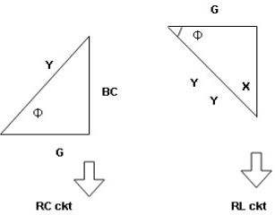
Quality factor / Q factor
The quality of resonance circuit is measured in terms of efficiency of L and C to stare energy and the efficiency of L and C to store energy as measured in terms of a factor called quality factor or Q factor it is expressed as
Q =  and Q =
The sharpness of tuning of R-L-C series circuit or its selectivity is measured by value of Q. As the value of Q increases, sharpness of the curve also increases and the selectivity increases.
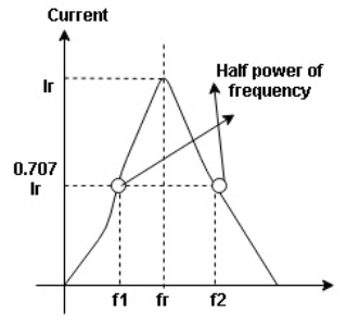
Bandwidth (BW) = f2 = b1
 and
and  are the frequency at which the power delivered to the resistor is reduced to 50% of the power delivered to it at resonance
  these frequencies are called as half power frequency
Bw = fr/Q


