Unit -6
Centrifugal & Axial Compressor

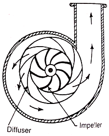
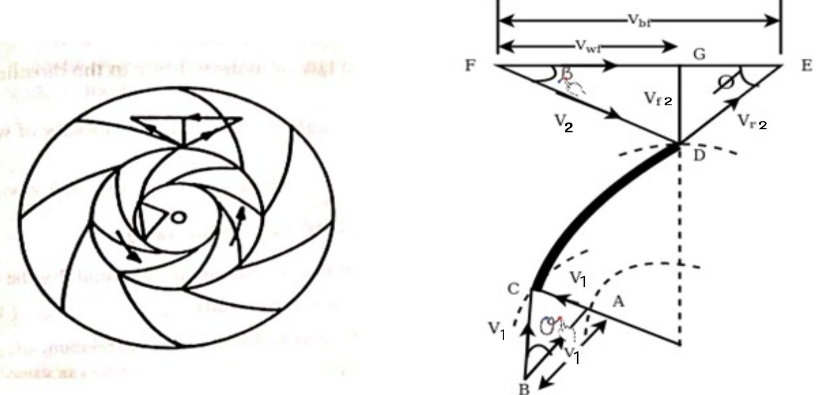
6.2 Construction
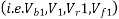
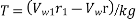
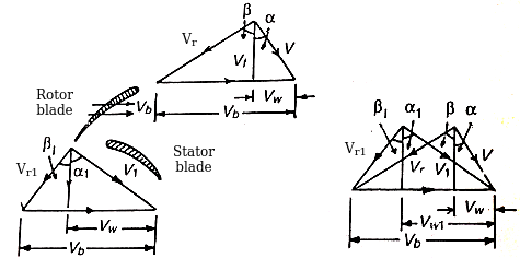
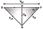
Let,  Linear velocity of the moving blade at inlet (BA)
V1 = absolute velocity of the air entering the blade (AC)
 Relative velocity of air to the moving blade at inlet (BC). It is vectorial difference between
  & V1
& V1
 velocity of flow at inlet
 = angle which the relative velocity makes with the direction of motion of the Blade and
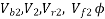 = Corresponding values at outlet


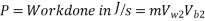
Let, m = mass of air compressed by the compressor in kg/s.
we know that according to Newton's second law of motion force in the direction of motion of blades (in Newtons)
F = mass of air flowing in kg/s × change in velocity of whirl in m/s

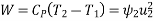
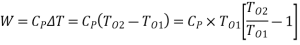
And work done in the direction of motion of the blades

Now power required to drive the compressor may be find out as usual by the relation,
The blades velocity at inlet or outlet,  may be find out by the relation
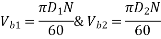
Where  and
and  are the internal and external diameters of the impeller
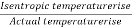
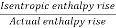
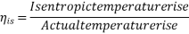
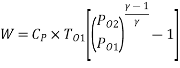
Isentropic efficiency, =
=  =
=  =
=

6.4 Euler's work
Now, for an angular velocity of impeller  rad/s
rad/s
Theoretical work required /kg of air = T×  w/kg
w/kg
Above Equation is known as Euler's equation and gives your Euler's work
Further, if air enters radially
Theoretical work required per kg =
The theoretical work required /kg also represents the theoretical or virtual head developed in the absence of losses.
Thus, virtual of theoretical head,  is given by

=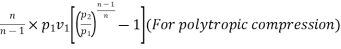
= 
= 
= 
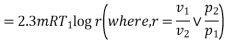
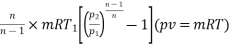
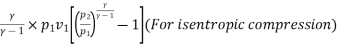
 = Initial pressure of air
 = Initial volume of air
 = Initial temperature of air
 = Corresponding values for the final
The fluid friction losses over the impeller are given by-

 loss in the inducer
 where,
 loss due to change of direction from axial to radial at the impeller inlet
 where
where  =loss coefficient= 0.1 to 0.2
 loss due to friction in the blade passages
 where
where  loss coefficient 0.2 to 0.4
 loss due to design deviations

 change in relative velocity due to design deviation
= 0.54 to 0.60
 = De friction loss in impeller

 = 0.003 to 0.008
II. Losses in the Diffuser:
III. Frictional Losses
IV. Shock Losses


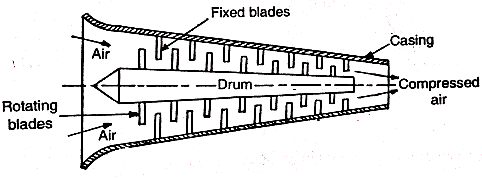
6.8 Construction of axial flow compressors


Work required/kg =
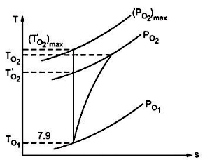
Above Equation is represented graphically on h-S diagram in Fig
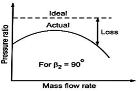
Cascade or diffuser efficiency
It is defined as the ratio of actual pressure rise to the isentropic pressure rise. Thus,

Friction in rotor and stator blade passages, shock losses, etc, reduce efficiency of the cascade (stage).
Polytropic efficiency:
 stage isentropic efficiency =
Polytropic efficiency =
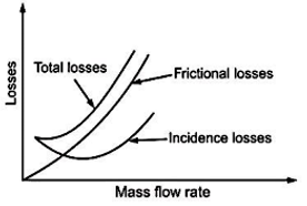
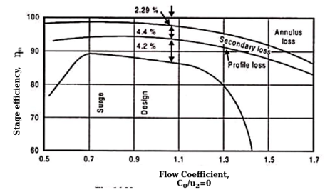
During the flow of fluid through a stage of a compressor various losses occur.
The pressure loss is due to three factors, namely:
(a) Profile losses On the Blade surface
(b) Skin friction on the annulus walls and
(c) Secondary flow losses
Figure illustrates various losses influencing the stage efficiency.
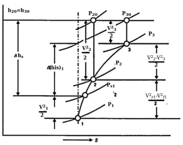
(a) Profile losses:
This is a pressure loss of two-dimensional cascade arising from the skin friction on the Blade surface and due to mixing of fluid particles after the blade.
(b) Skin friction losses on the annulus walls
The total pressure loss arise from the skin friction on the annulus walls and some secondary loss.
(c) Secondary flow losses
These losses occur due to combined effects of curvature and boundary layer.
2. Annulus losses. Because of adverse pressure gradient in compressors the boundary layer along the annulus walls taken as the flow progresses. This will reduce the area available for floor and lead to drop in axial velocity through the compressor.
3. Secondary losses. The loss occurring in the regions of flow near the end walls due to presence of unwanted circulatory or cross flows. This type of secondary flow develops due to turning of flow through the blade channel in the pressure of annulus wall boundary layers. Secondary flows in the cascade will also affect the profile and annulus losses.
4. Tip clearance losses. the loss arising due to the clearance between the moving blade and the casing is the clearance loss. The flow leaks from pressure side towards the suction side.
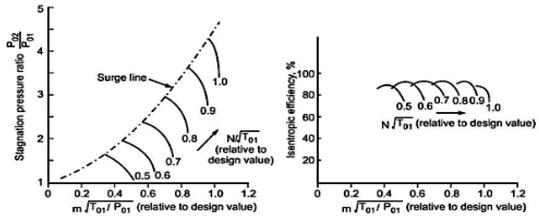
(a) Shows stagnation pressure rise vs non dimensional mass flow,  isentropic efficiency is for fixed values on non dimensional speed
  from figure
(b) It is clear that the characteristics for fixed values of  a much narrow range of mass flow then in the case of centrifugal compressor. At high rotational speeds the constant speed line become very steep and ultimately become vertical. The same limitations occur at either end of the
  due to surging and choking.
Numerical
1. Centrifugal compressor delivers 10 off air when running at 10000 rpm. The air is drawn in at 1 bar and 300 K and delivered at 4 bar. The isentropic efficiency is 80%. The blades are radial at outlet and velocity of flow is constant = 64 m/s. The outlet diameter of impeller is twice the inner diameter. Take slip factor as 0.9. Find
(i) Temperature of air at outlet tip of impeller
(ii) power required to drive the compressor
(iii) Impeller diameters at inlet and outlet
(iv) Impeller blade angle at inlet
(v) Diffuser blade angle at inlet
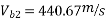
Ans. Given: volume flow rate,  (radial at outlet),
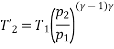
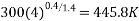
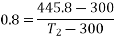
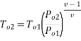
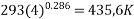
(i) Temperature of Air at outlet 
Isentropic temperature at exit,


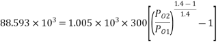
(ii) Power required,
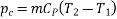

=
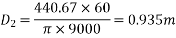
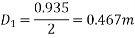
(iii) Impeller Diameter Inlet and Outlet


But, 
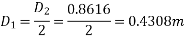
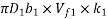
(iv) Impeller Blade Angle at inlet 

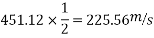
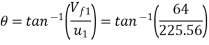
=
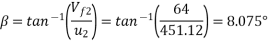
(v) Diffuser Blade Angle at Inlet
2. A centrifugal compressor running at 9000 rpm delivers  of free air. The air is compressed from 1 bar and 20°C to a pressure ratio of 4 with an isentropic efficiency of 82%. blades are radial at outlet of impeller and flow velocity of 62 m/s may be assumed throughout constant. The outer radius of impeller is twice the inner and slip factor may be assumed as 0.9. The Blade area coefficient of 0.9 may be assumed at inlet.
Calculate-
(i) Final temperature of air
(ii) Theoretical power
(iii) Impeller diameter at inlet and outlet
(iv) Impeller blade angle at inlet
(v) Diffuser blade angle at inlet
(vi) Breadth of impeller at inlet
Ans. Given, N =9000 rpm
Free air delivery, 


Blade area coefficient =


Actual temperature rise,
Final Temperature of Air
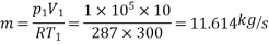
Mass flow rate of air,

Theoretical Power


POWER REQUIRED TO COMPRESS 1 KG OF AIR PER RADFIAL BLADES IS GIVEN BY

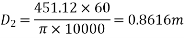
Impeller diameters at Inlet and Outlet

Volume flow rate V is given by

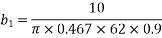
Breadth of impeller at inlet

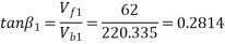

Impeller blade angle at inlet


Diffuser blade angle at inlet

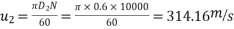
3. The impeller of a centrifugal compressor has the inlet and outlet diameter of 0.3 and 0.6 m. respectively. The intake is from the atmosphere at 100 kPa and 300 K without any whirl component. The outlet blade angle is  . The speed is 10000 rpm and the velocity of flow is constant at 120m/s. if the blade width at intake is 6 cm, calculate:
(i) Specific work
(ii) Exit pressure
(iii) Mass flow rate
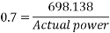
(iv) Power required to drive compressor if the overall efficiency can be assumed at 0.7.
Ans. 
Calculate specific work

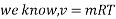
We know, 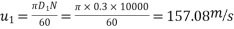
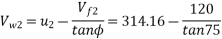
From outlet velocity triangle,


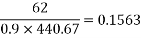
Now, exit pressure
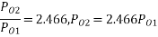

Volume flow rate is given by


Theoretical power, 
= 
Overall efficiency, 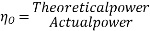
Reference:


