Unit -5
Centrifugal Pumps
- Single stage pumps:
- It is known as single impeller pump.
- It is simple in design and easy in maintenance.
- It is ideal for large flow rates and low pressure installations.
- Two stage pump:
- It has two impellers operating side by side.
- It is used for medium use applications.
- Multistage Pumps:
- It has three or more impellers in series.
- They are used for high head applications.
- Axial split:
- In these types of pumps the volute casing is split axially and split line at which the pump casing separates is at the shaft’s center – line.
- Radial split:
- In it pump case is split radially, the volute casing split is perpendicular to shaft centre line.
- Single suction:
- It has single suction impeller which allows fluid to enter blades only through a single opening.
- Double Suction:
- It has double suction impeller which allows fluid to enter from both the sides of blades.
- They are most common types of pumps.
- Single volute pump:
- It is usually used for low capacity pumps, as it has small volute size.
- Double volute pump:
- It has two volutes which are placed 180 degrees apart.
- It has a good capability of balancing radial loads.
- Horizontal Centrifugal pumps:
- It is suitable for low pressure.
- Vertical Centrifugal pumps:
- It can easily withstand higher pressure loads.
- It is more expensive than horizontal pumps.
1. Impeller
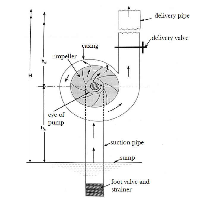
2. Casing
a) Volute casing:
b) Vortex casing
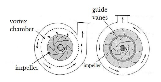
Vortex Casing Casing with Guide Blades
c) Casing with guide blades or turbine pump
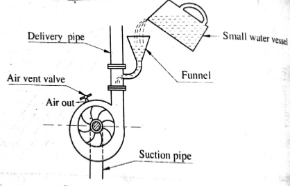
3. Suction pipe with a foot valve and strainer
4. Delivery pipe.

2. Delivery head

3. Static head

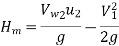
4. Manometric head

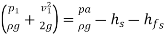
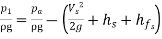
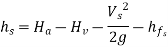
It is given by the following expressions
a) 
=
=
b) 
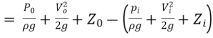
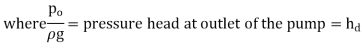
 Vertical height of the outlet of the pump from datum line and
 Corresponding values of pressure head, velocity head and datum head at the inlet of the pump,
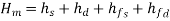
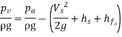
(c) 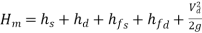
Where  Suction head
 Delivery head
 Frictional head loss in suction pipe
 Frictional head loss in the delivery pipe and
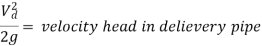
 Velocity of water in delivery pipe
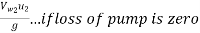
The term  is a small quantity as compared to other terms. Generally it is neglecting then


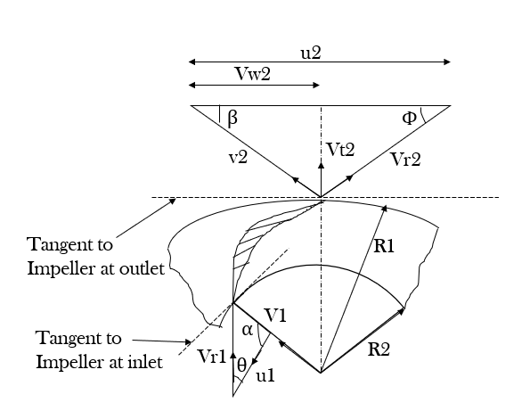
Let, N= speed of the impeller in r.p.m
 Diameter of impeller at inlet
 Tangential velocity of impeller at inlet=
 Diameter of impeller at Outlet
 Tangential velocity of impeller at outlet=
 Absolute velocity of water at inlet
 Relative velocity of water at inlet
 = Angle made by absolute velocity
  at inlet with the direction of motion of vane
 = Angle made by relative velocity (
 at inlet with the direction of motion of vane and
  are the corresponding values at outlet.
A centrifugal pump is the reverse of a radially inward flow reaction turbine. But in case of radially inward flow reaction turbine, the work done by the water on the runner per second per unit weight of water striking per second is given by equation
Work done by the impeller on the water per second per unit weight of water striking per second = - [work done in case of turbine]
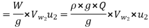
Work done by impeller on water per second

Where W = weight of water=.  ×g×Q
×g×Q
Where Q= Volume of water
And, Q= Area × velocity of flow =
Where  are width of impeller at inlet and outlet and
  velocity of flow at inlet and outlet
From the outlet velocity triangle

Then 
 …………………. (1)
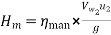
Under the ideal condition assumed above the manometric efficiency of the pump will become
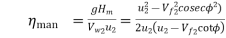 ………………….. (2)


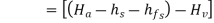
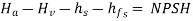
NPSH= Total head at inlet of the pump - vapour pressure head
 …………………. (1)

Substituting this value in equation (1) we get
NPSH=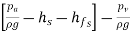
= 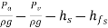
Where  atmospheric pressure head
  vapour pressure heat
 ……………………….. (2)


but we have


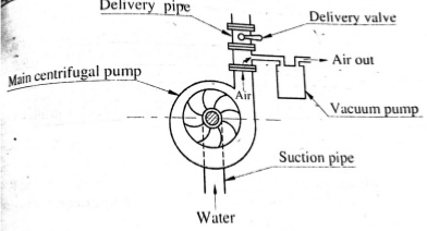
2. With vacuum pump
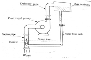
3. With jet pump
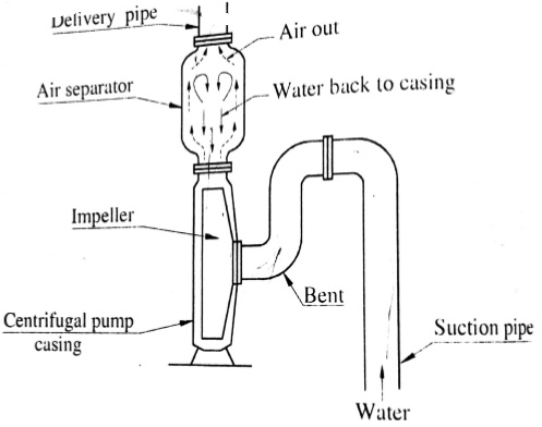
4. With separator
Installation of the pumps consists of:
(1) Location of the pump,
(2) Proper foundation, and
(3) Alignment of the coupling.

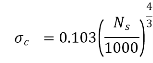
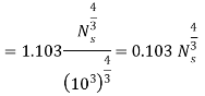
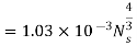
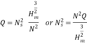
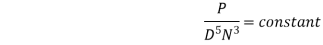
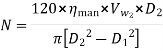
Expression for specific speed for a pump
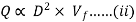
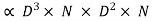
The discharge Q for a centrifugal pump is given by the relation
Q= Area ×velocity of flow

D= diameter of the Impeller of the pump
B = width of the impeller
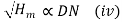
We know that B D
D
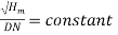
From equation (i) we have
We also know that tangential velocity is given by
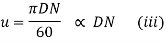
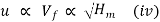
Now the tangential velocity (u) and velocity of flow  are related to the manometric head
  as
as
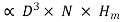
Substituting the value of u in equation (iii) we get
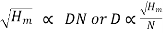
Substituting the values of D in equation (ii)
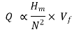


Where K is constant of proportionality
If, 
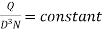
Substituting these values in equation (v) we get


Substituting the value of K in equation (v) we get

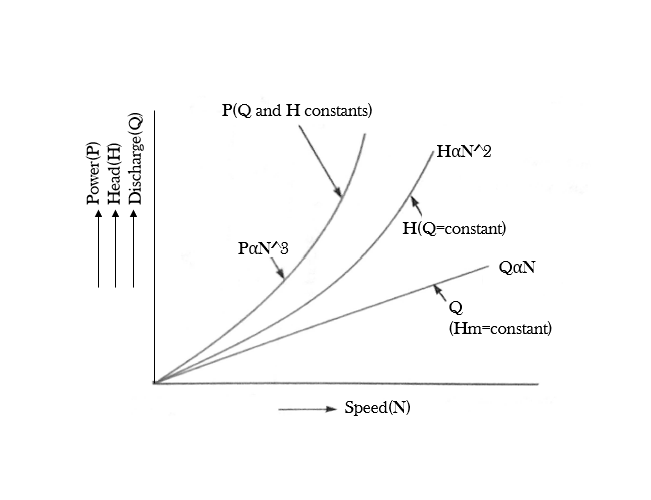
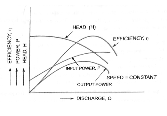
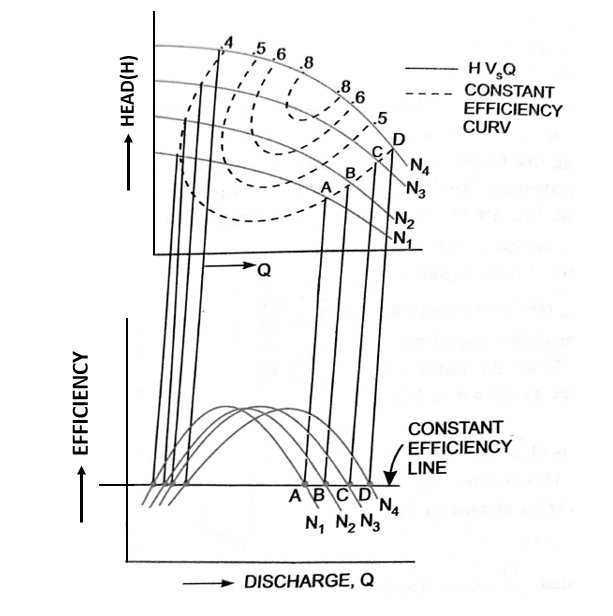
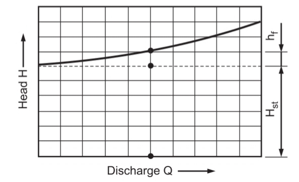
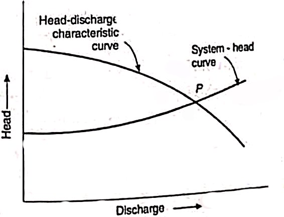
Characteristic curves of centrifugal pumps
Main characteristic curves


Operating characteristic curves


Constant efficiency curves


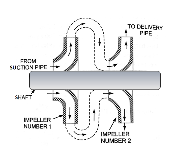
Let. n = number of impellers mounted on the same shaft.
 = developed by each impeller
Then total head developed=
The discharge passing through each impeller is same.
Multistage centrifugal pumps for high discharge
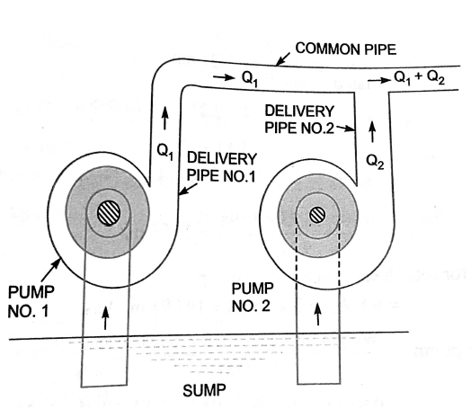
Let n=number of identical pumps arranged in parallel
Q=discharge from one pump
Total discharge= n × Q
(Ns)m = (Ns)p
 =
= 
2. Tangential velocity  also
also 
 =
= 
3. We have, 


 =
= 
4. Power of the pump 


 =
= 
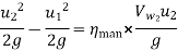
Minimum Speed for starting A centrifugal pump
Where  =Tangential velocity of impeller at outlet=
 and
and
 =Tangential velocity of impeller at inlet =
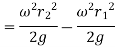
Head due to pressure rise in impeller =
The flow of water will commence only if
Head due to pressure rise in impeller 

For minimum speed we must have  …………………. 1
But from we have 
Substituting this value of  in equation 1
 and
and 
Substituting the values of  and
and  in equation
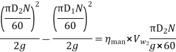
Dividing by  we get
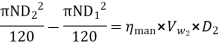
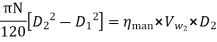
Above equation gives the minimum starting speed of the centrifugal pump
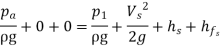
Maximum Suction Lift (or Suction Height)
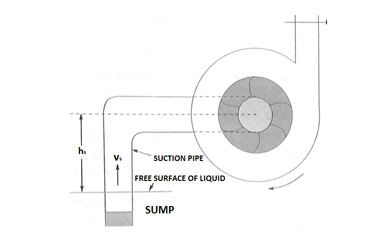


Let  =Suction lift
 …………………………. 1
Where  =Atmospheric pressure on the free surface of liquid
 =Velocity of liquid at the free surface of the liquid =0
 =Height of free surface from datum line =0
 =Absolute pressure at the inlet of pump
 =Velocity of liquid through suction pipe=
 =Height of inlet of pump from datum line =
 =Loss of head in the foot valve, strainer and suction pipe=
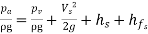
substitute the above values in equation 1
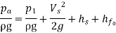
 …………………… 2
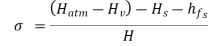
 where
where  = vapour pressure of the liquid in absolute units
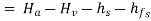
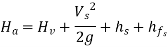
Now the equation 2 becomes as
 ……………..3
 =Atmospheric pressure head =
 =Vapour pressure head =
Now equation 3 becomes as
Numericals

Solution
Given
Discharge, Q=
Speed , N=1450 rpm
Head  =25m
=25m
Diameter at outlet  =250mm=0.25m
Width at outlet  =50mm=0.05m
Manometric efficiency 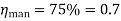
Tangential velocity of impeller at outlet

Discharge is given by 
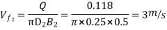
Using equation 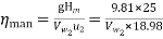
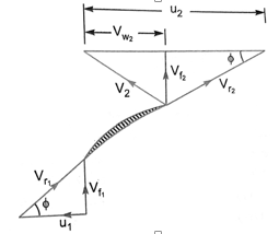
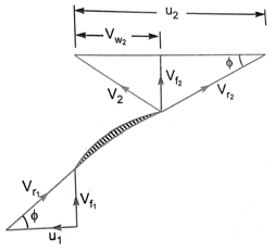
From outlet velocity triangle we have
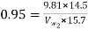
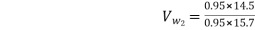
2. A centrifugal pump delivers water against a net head of 14.5 metres and a design speed of 1000 rpm. The vanes are curved back to an angle of 30 degree with the periphery. The impeller diameter is 300 mm and outlet width is 50mm. Determine the discharge of the pump if manometric efficiency is 95%.
Given
Net head 
Speed N=1000 r.p.m
Vane angle at outlet 
Impeller diameter 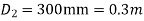
Outlet width 
Manometric efficiency 
Tangential velocity of impeller at outlet
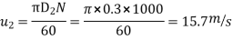
Now using equation 
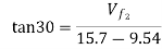
 = 9.54m/s
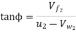
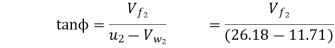
from outlet velocity triangle


3. A centrifugal pump having outer diameter equal to two times the inner diameter and running at 1000 rpm works against a total head of 40m. The velocity of flow through the impeller is constant and equal to 2.5m/s .The vanes are set back at an angle of 400 at outlet . If the outer diameter of the impeller is 500mm and width at outlet is 50mm Determine
Given
Speed N=1000rpm
Head 
Velocity of flow 
Vane angle at outlet 
Outer diameter of impeller 
Inner diameter of impeller 
Width at outlet 
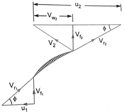
Tangential velocity of impeller at inlet and outlet are
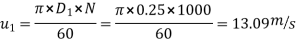
And 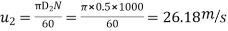
Discharge is given by 
From inlet velocity triangle 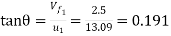
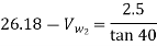
from outlet velocity triangle we have
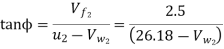

2. Work done by impeller on water per second is given by equation as
=119227.9Nm/s
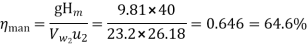
3. Manometric efficiency
4. The outer diameter of an impeller of a centrifugal pump is 400mm and outlet width is 50mm. The pump is running at 800 rpm and is working against a total head of 15m. The vanes angle at outlet is 400 and manometric efficiency is 75%. Determine
Given
Outer diameter 
Width at outlet 
Speed N=800rpm
Head 
Vane angle at outlet 
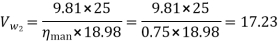
Manometric efficiency 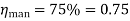
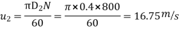
Tangential velocity of impeller at outlet

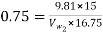
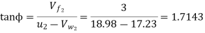
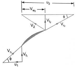
From the outlet velocity triangle
Velocity of water leaving the vane

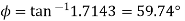
Angle made by absolute velocity at outlet
Discharge through pump is given by

5. A three stage centrifugal pump has impellers 40cm in diameter and 2 cm wide at outlet. The vanes are curved back at the outlet at 450 and reduce the circumferential area by 10%. The manometric efficiency is 90% and the overall efficiency is 80% Determine the head generated by the pump when running at 1000 rpm delivering 50 litres per second. What should be the shaft horse power ?
Given
Number of stages n=3
Diameter of impeller at outlet 
Width at outlet 
Vane angle at outlet 
Reduction in area at outlet =10%= 0.1
Area of flow at outlet =
Manometric efficiency 
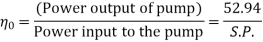
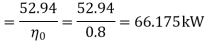
Overall efficiency 
Speed N=1000rpm
Discharge Q = 50litres/s = 0.05 
Velocity of flow at outlet 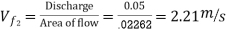
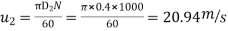
Tangential velocity of impeller at outlet,
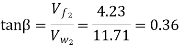
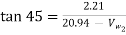
from velocity triangle at outlet,


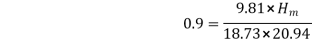
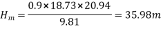
Total heat generated by pump =
Power output of the pump= 

Reference:


