Unit – 3
Reaction Water Turbines
Types of Reaction Turbine are
1. Radial Flow Turbines
Inward Flow Turbines
Outward Flow Turbines
2. Axial Flow Turbines
3. Mixed Flow Turbines
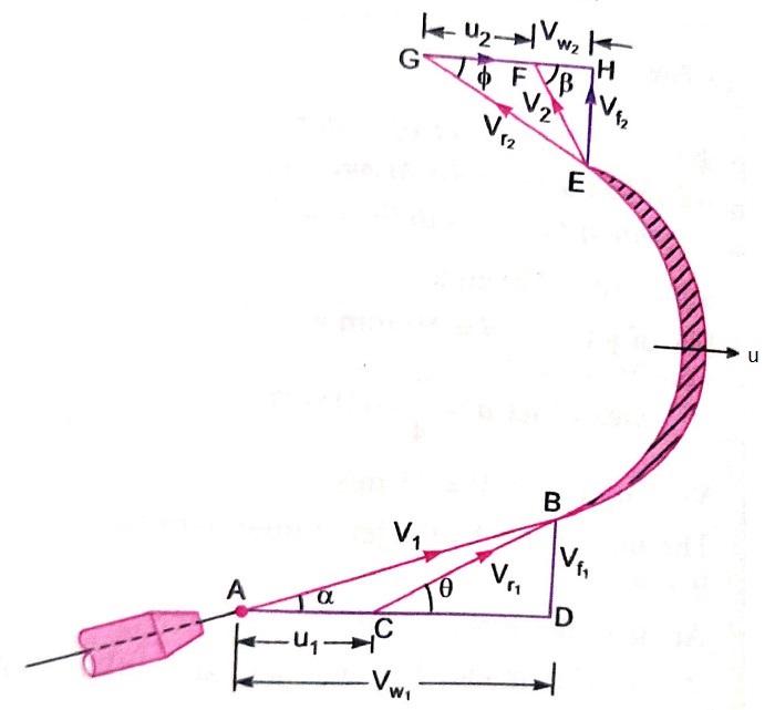
The work done per second on the runner by water is given by equation


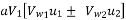
=  Q[
Q[
Where
 Velocity of whirl at inlet and outlet
 = Tangential velocity of wheel of inlet and outlet
The work done per second per unit weight of water per second
=
= 
=
Hydraulic efficiency = 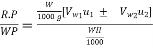
=
Where
RP = Runner power
WP = Water power
If discharge is radial 
 = =
= =


 =
=
If 
 =
=
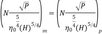
1) Speed (N)
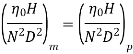
2) Head (H)
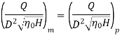
3) Discharge (Q)
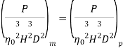
4) Power (P)
5) Overall efficiency (
6) Gate opening
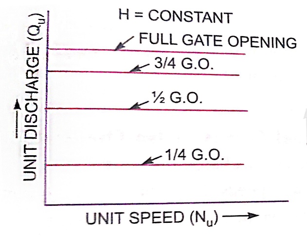
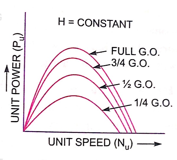
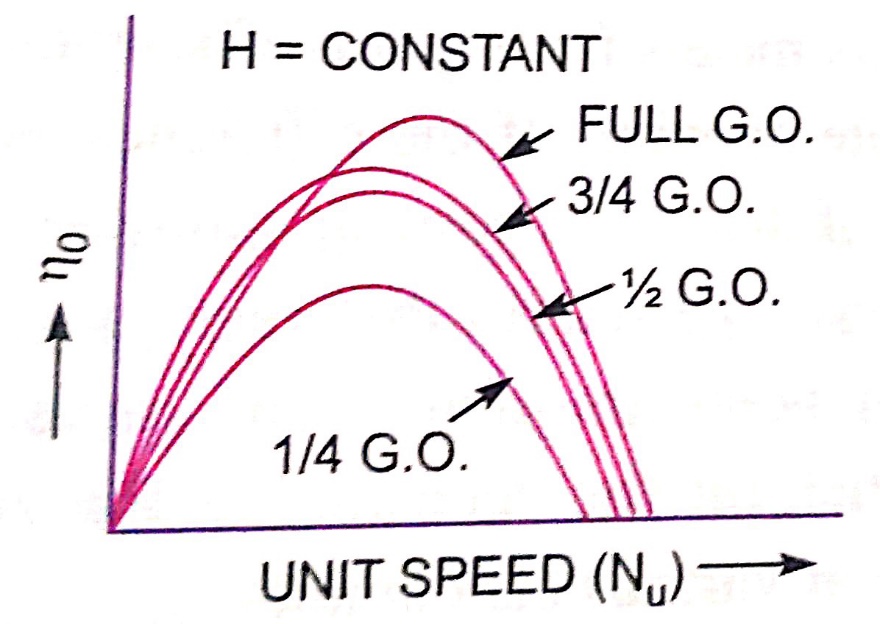
Constant head curves
For a Pelton wheel
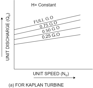
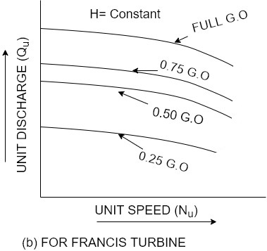
For reaction turbines


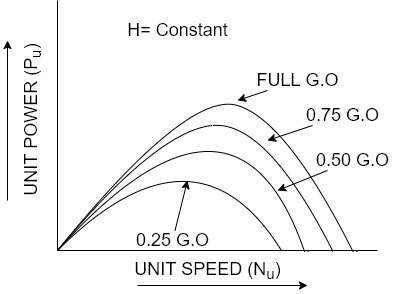
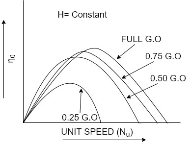
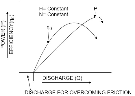
Operating characteristic curves for constant speed curves
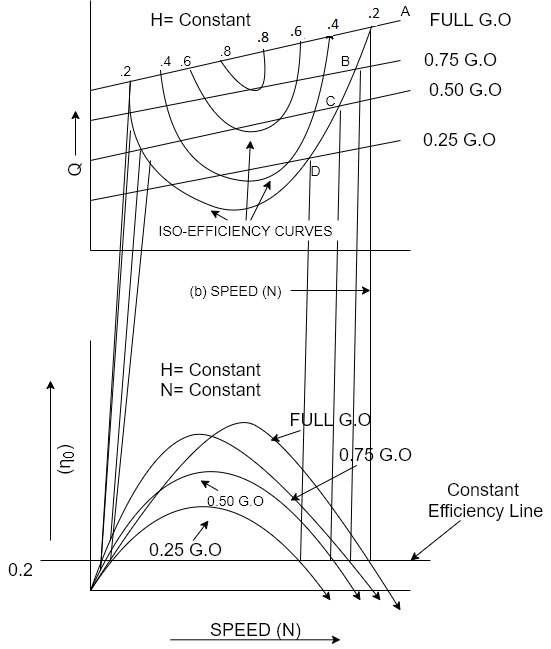
Constant efficiency curves or Muschel curves or iso-efficiency curves


1) It permits negative head to be established at the outlet of the runner and thereby increase the net head on the turbine.
2) The turbine may be placed above the tail race without any loss of net head and hence turbine may be inspected properly.
3) It converts a large portion of kinetic energy (  at the outlet of turbine into useful pressure energy.
Types of draft tubes
The following are the important types of draft tubes which are commonly used
1) Conical draft tube
2) Simple elbow tubes
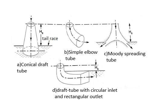
3) Moody spreading tubes
4) Elbow draft tubes with circular inlet and rectangular outlet
Draft tube theory:-
Consider a conical draft tube as shown in figure.
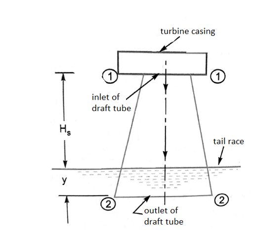
 Vertical height of draft tube above the tail race
y = distance of bottom of draft tube from tail race
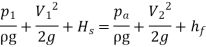
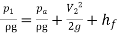
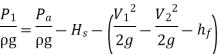
Applying Bernoulli's equation to inlet (section 1-1) and outlet (section 2-2) of the draft tube and taking section 2-2 as the datum line we get
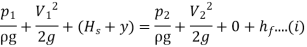
 loss of energy between section 1-1 and 2-2.
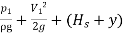
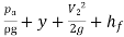
But,  atmospheric pressure head + y
= 
Substituting this value of  in equation (i) we get
 =
=
 -
-
=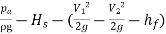
In above equation,  is less than atmospheric pressure.
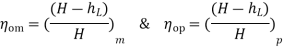
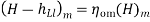
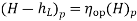
Efficiency of draft tube
The efficiency of a draft tube is defined as the ratio of actual conversion of kinetic head into pressure head in the draft tube to the kinetic head at the inlet of the draft tube.
Mathematically,
 =
= 
 Velocity of water at inlet of draft tube
 Velocity of water at outlet of draft tube and,
 Loss of head in the draft tube
Theoretical conversion of kinetic head into pressure head in draft tube = 
Actual conversion of kinetic head into pressure head=
= 
Precautions against cavitation
The following precautions should be taken against cavitation
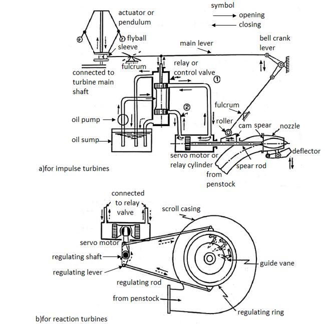
1) Servo motor also known as relay cylinder.
2) Relay valve known as control valve.
3) Actuator
4) Oil sump
5) Oil pump which is driven by belt connected to turbine main shaft.
6) A system of oil supply pipes connecting the oil sump with servo motor.


Numericals

a) Volume flow rate
b) The power developed and
c) Hydraulic efficiency
Sol.
Given,
Speed of turbine, N=450 r.p.m
Head, H= 120m
Diameter at inlet, 
Flow area = 
Angle made by absolute velocity at inlet.  = 20°
= 20°
Angle made by the relative velocity at inlet Ѳ =60°
Whirl at outlet 
Tangential velocity of turbine at inlet
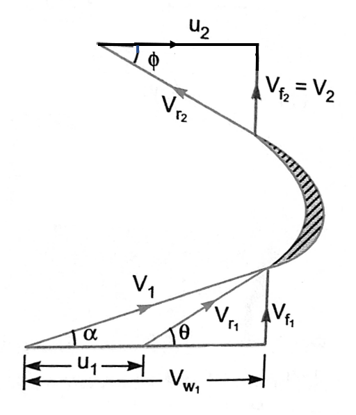
From inlet velocity triangle

Also, tan Ѳ =
 60
60

a) Volume flow rate 

b) Work done per sec on the turbine =
=
Power developed in KW= Work done per second/1000=5272402/1000=5272.402KW
c) Hydraulic Efficiency
=0.8595 = 85.95%
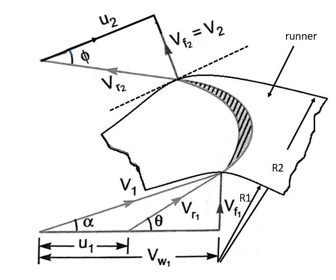
2. An inward flow reaction turbine has external and internal diameters as 1.0 m and 0.6 m respectively. The hydraulic efficiency of the turbine is 90% when the head on the turbine is 36m. The velocity of flow at inlet is 2.5 m/s and discharge at outlet is radial. If the vane angle at outlet is 15 degree and width of the wheel is 100 mm at inlet and outlet, determine
I) The guide blade angle
II) Speed of the turbine
III) Vane angle of the runner at inlet
IV) Volume flow rate of turbine and
V) Power developed
Sol.
Given
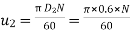
External diameter=
Internal Diameter 
Hydraulic Efficiency ηh=90%=0.90
Head H=36m
Velocity of flow at outlet 
Discharge in radial 
Vane angle at outlet 
Width of wheel 
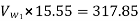
For hydraulic efficiency 
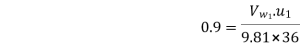
 ………………………….(1)
From outlet velocity triangle 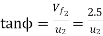
 m/s
m/s

Substituting this value of  in equation (1)
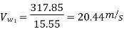
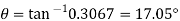
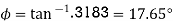
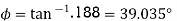
1) Guide blade angle (
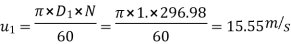
From inlet velocity triangle 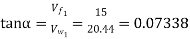
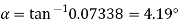
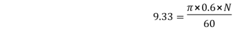
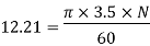
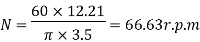
(ii)Speed of the turbine N=296.98rpm
(iii)Angle of runner at inlet t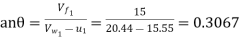
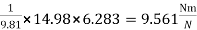
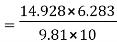
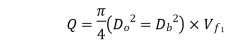
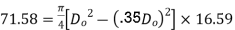
 Volume flow rate of turbine =
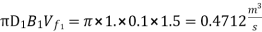
(v) Power developed (in KW)= Work done per second /1000 = 
=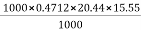 =149.76kW
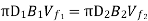
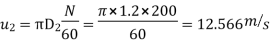
3. An outward flow reaction turbine has internal and external diameter of the runner as 0.6 m and 1.2 m respectively. The guide blade angle is 15 degree and velocity of flow through the runner is constant and equal to 4 m/s. if the speed of the turbine is 200 r.p.m head on the turbine is 10m and discharge at outlet is radial, determine
(i) The runner vanes angles at inlet and outlet
(ii) Work done by the water on the runner per second per unit weight of water striking per second
(iii) Hydraulic efficiency and
(iv) The degree of reaction
Sol.
Internal Diameter 
External Diameter 
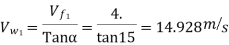
Guide blade angle 
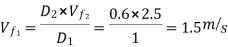
Velocity of flow 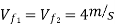
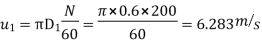
Speed N=200rpm
Head H=10m
Discharge at outlet = Radial
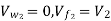
Tangential velocity of runner at inlet and outlet are:
From the inlet velocity triangle 

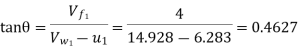
θ = tan-1 .4627=24.83
From outlet velocity triangle 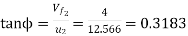
2. Work done by water per second per unit weight of water striking per second
=
=
3. Hydraulic efficiency


4. In this question the velocity of flow is constant through the runner  the degree of reaction is given by equation
R=1-
Here,

Substituting the value of  we get,
R=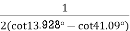
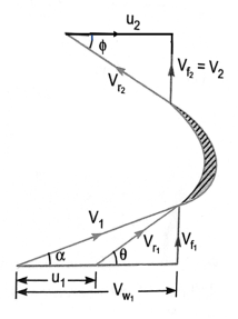
4. Kaplan turbine working under a height of 20m develops 11772 kW shaft power. The outer diameter of the runner is 3.5 m and inner diameter is 1.75 m. The guide blade angles at the extreme edge of the runner is 35 degree. The hydraulic and overall efficiencies of the turbines are 88% and 84% respectively. If the velocity of wheel is zero at outlet, determine
(i)Runner vane angles at inlet and outlet at the extreme edge of the runner and
(ii) Speed of the turbine
Sol.
Given
Head, H=20m
Shaft power, S.P.=11772Kw
Outlet diameter of runner, 
Hub diameter, 
Guide blade angle, 
Hydraulic efficiency, 
Overall efficiency, 
Velocity of whirl at outlet=0
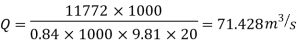
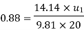
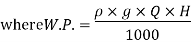
Using the relation, 
Where, W.P. =

0.84 

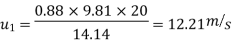
From the velocity triangle, tan 
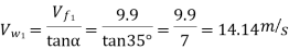
Using the relation for hydraulic efficiency,

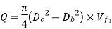
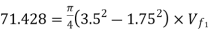
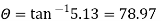
(i) Runner vane angles at inlet and outlet at the extreme edge of the runner are given as
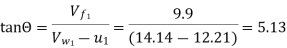
For Kaplan turbine,

From outlet velocity triangle, 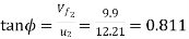
(ii) Speed of turbine is given by 
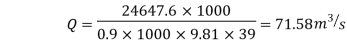
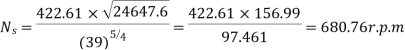
5. A Kaplan turbine develops 2464 7.6 kW power at an average height of 39 meters. Assuming a speed ratio of 2, flow ratio of 0.6, diameter of the boss equal to 0.35 times the diameter of the runner and an overall efficiency of 90%, calculate the diameter, speed and specific speed of the turbine.
Sol. Given,
Shaft power, S.P.=24647.6BkW
Head, H=39m
Speed ratio,  0
0

Flow ratio, 

Diameter of boss =0.35 Diameter of runner
Overall efficiency , 
Using the relation, 


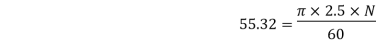
(ii)Speed of the turbine is given by 
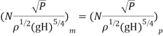
(iii)Specific speed is given by  , where P=Shaft power in Kw
6. A conical draft tube having inlet and outlet diameters 1m and 1.5 m discharges water at outlet with a velocity of 2.5m/s. The total length of the draught tube is 6m and 1.20m of the length of draft tube is immersed in water. If the atmospheric pressure head is 10.3 m of water and loss of head due to friction in the draft tube is equal to 0.2 × velocity head at outlet of the tube, find:
(i)Pressure head at inlet and
(ii)Efficiency of the draft tube
Sol. Given,
Diameter of inlet,  1.0 m
1.0 m
Diameter at outlet,  1.5 m
1.5 m
Velocity at outlet, 
Total length of tube, 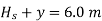
Length of tube in water, y=1.20m
 =6.0 - 1.20 = 4.80 m
Atmospheric pressure head, 
Loss of head due to friction,  0.2
0.2 Velocity head at outlet
= 
Discharge through tube, 
Velocity at inlet, 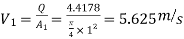
(i)Pressure head at inlet 
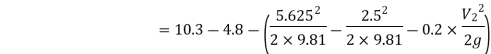

=4.27 m (abs.)
(ii)Efficiency of draft tube
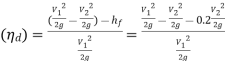
=
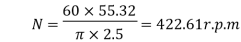
7.A turbine is to operate under a head of 2.5 m at 200 r.p.m. The discharge is 9 cumec. If the efficiency is 90%, determine the performance of the turbine under a head of 20 meters.
Sol.
Given,
Head of turbine,  = 25m
= 25m
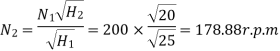
Speed,  =200 r.p.m
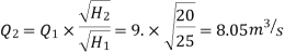
Discharge, 
Overall efficiency, 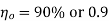
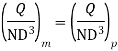
Performance of the turbine under a head,  , means to find the speed, discharge and power developed by the turbine when working under the head of 20 m.
Let for the head ,  , Speed=
 , discharge=
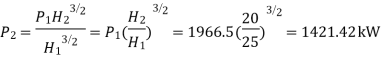
 and power =
Using the relation, 
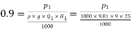
 1986.5 kW
Using the relation , 
Also , 
And, 
Reference:
1. Fluid Mechanics & Hydraulics Machines- R.K. Bansal
2. Hydraulics & Fluid Mechanics – Modi & Seth


