Unit -1
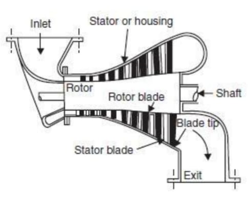
Introduction to Turbo Machinery & Impact of Jet
The principle component of a turbo machine are :
1.Based on energy transfer
2.Based on fluid flowing in turbo machine
3.Based on direction of flow through the impeller or vanes or blades, with reference to the axis of shaft rotation
4.Based on condition of fluid in turbo machine
5.Based on position of rotating shaft
Turbomachines | Positive displacement machines |
1. It creates thermodynamics and dynamic action between rotating element and following fluid, energy transfer takes place if pressure and momentum changes. | 1. It creates thermodynamics and mechanical action between moving member and static fluid, energy transfer takes place with displacement of fluid. |
2. It involves a study flow of fluid and rotating motion of mechanical element. | 2. It involves a unsteady flow of fluid and reciprocating motion. |
3. They operate at high rotational speed. | 3. They operate at low speed. |
4. Change of phase during fluid flow causes serious problems in Turbo machine. | 4. Change of phase during fluid flow causes less problems in positive displacement machines. |
5. Efficiency is usually less. | 5. Efficiency is higher. |
6. It is simple in design. | 6. It is complex in design. |
7. Due to rotatory motion vibration problems are less. | 7. Due to reciprocating motion vibration problems are more. |
8. E.g. hydraulic turbines, gas turbines, steam turbines etc. | 8. E.g. I.C engines , reciprocating air compressor, pumps etc |
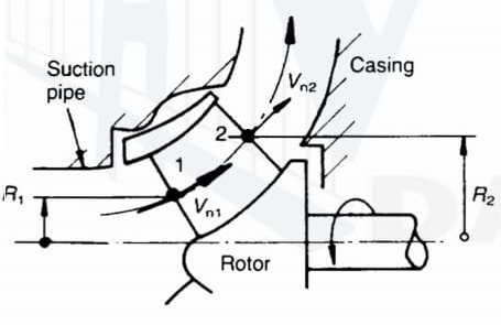
Euler’s Equation
dM1 = ( Vn1 da1) Vu1 R1
dM2 = ( Vn2 da2) Vu2 R2
Thus the total moments of momentum are
M1 = 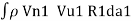
M2 = 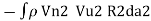
The fluid torque is the net effect given by
T = M1 + M2
= ………………. 1
It is assumed that Vu R is a constant across each surface and it is noted that  is the mass flow rate m.
Then equation (1) becomes
T = m(Vu1 R1 - Vu2 R2) ………………………………………….. 2
The rate of doing work is  T and since
  R is the rotor peripheral velocity u
at radius R, equation (2) can be transformed to give work done per unit
mass:
g H = u1 Vu1 - u2 Vu2
This is one form of the Euler equation.
Application of the First Law of Thermodynamics
Work output of the turbomachine = Total fluid energy at inlet - Total fluid energy
at outlet
= E1 – E2
On the basis of unit mass flow rate,
W = e1 – e2
=  -
- 
Where W, is the “specific work” of a turbomachine. It is the work interaction of 1 kg of fluid while flowing over the rotor of the turbomachine.
W =  -
- 
Application of the Second Law of Thermodynamics

The two types of losses are as following
2. External losses:
It is based on law of conservation of momentum or on the momentum principle, which states that the net force acting on a fluid mass is equal to the change in momentum of flow per unit time in that direction.
The force acting on a fluid mass m is given by the Newtons second law of motion.
F = m x a
Where a is the acceleration acting in the same direction as force F
But a = 
F = m x 
=  m is constant can be taken inside the differential
Above equation is known as the momentum principle.
It can be written as F dt = d(mv)
Which is known as the momentum equation & states that the impulse of force F acting on a fluid of mass m in a short interval of time dt is equal to the change of momentum d(mv) in the direction of force.
Applications of the Impulse - Momentum Equation
1.For any problems involving F, v, t:
The impulse Momentum equation may be used for any problems involving the variables force F , velocity v, and time t. The IM equation is not directly helpful for determining acceleration, a, or displacement, s.
2. Helpful for impulsive forces:
The IM equation is most helpful for problems involving impulsive forces. Impulsive forces are relatively large forces that act over relatively short periods of time for example during impact. If one knows the velocities, and hence momenta, of a particle before and after the action of an impulse, then one can easily determine the impulse. If the time of impulse is known, then one can calculate the average force that act during the impulse.
3.For problems involving graph of F vs. t :
Some problems give a graph of Force vs. time. The area under this curve is impulse.
1.8.1. Force exerted by the jet on a stationary vertical plate
Consider a jet of water coming out from the nozzle, strikes a flat vertical plate as shown in Fig
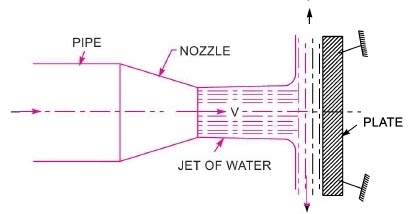
V = velocity of the jet
d = diameter of the jet
a = area of the cross section of the jet
= 
The jet after striking the plate, will move along the plate.
But the plate is at right angles to the jet.
Hence the jet after striking will get deflected through 90°.
Hence the component of the velocity of jet, in the direction of jet, after striking will be zero.
The force exerted by the jet on the plate in the direction of jet,
 =rate of change of momentum in the direction of force
= 

= 
=
= (Mass/sec) x (velocity of Jet before striking - velocity of Jet after striking)
= 
= 
1.8.2. Force exerted by Jet on stationary inclined flat plate
Let Jet of water, coming out from the nozzle, strikes and inclined flat plate as shown in Fig.
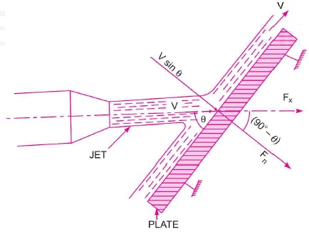
V = Velocity of jet in the direction of 
 = Angle between the jet and plate
a = area of cross section of the jet
Then mass of water per second striking the plate = 
If the plate is smooth and if it is assumed that there is no loss of energy due to impact of the jet, then Jet will move over the plate after striking with a velocity equal to initial velocity.
The force exerted by the jet on the plate in the direction normal to the plate.
 = mass of Jet striking per second × [ initial velocity of Jet before striking in the direction of
  - final velocity of Jet after striking in the direction of
  ]
]
=  θ
θ
 = component of
  perpendicular to flow
=  θ) =
θ) =  θ =
θ =  θ
θ  θ
θ
= 
 =component of
  perpendicular to flow.
=  θ) =
θ) =  θ =
θ =  θ
θ  θ
θ
1.9.1. Force on flat vertical plate moving in the direction of jet
Fig. shows a jet of water striking a flat vertical plate moving with a uniform velocity away from the jet.
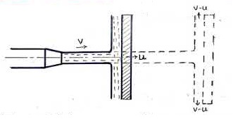
Let , V =velocity of jet
a = area of cross section of jet
u = velocity of the flat plate
In this case, Jet does not strike the plate with a velocity  but it strikes with a reflective velocity which is equal to the absolute velocity of jet of water minus the velocity of the plate.
Therefore, relative velocity of the jet with respect to plate= V- u
Mass of water striking the plate per sec
=  ×area of jet × velocity with which Jet strikes the plate
=  a[V-u]
Force exerted by the jet on the moving plate in the direction of the jet,
 =mass of water striking per ×[initial velocity-final velocity]
= a[V-u] [(V-u)-0]
= 
Work done per second by the jet on the plate =
=
1.9.2. Force on the inclined plate moving in the direction of the jet
Let a jet of water strikes on the inclined plate, which is moving with uniform velocity in the direction of the jet as shown in fig.
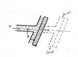
Let V=Absolute velocity of jet of water
u = Velocity of the plate in the direction of jet
a = Cross sectional are of jet
 Angle between jet and plate
Relative velocity of jet and water=V- u.
Therefore, Mass of water striking per second=  a[V-u]
If the plate is smooth and loss of energy due to impact of the jet is assumed zero, the jet of water on the plate with a velocity equal [V- u]
The force exerted by the jet water on the plate in the direction normal to the plate is given as
 Mass striking per second
  [Initial velocity - Final velocity]
=  a(V-u)[(V-u)sin θ]
= sin θ
sin θ
This normal force  is resolved into two components namely
  in the direction of jet and perpendicular to the direction of the jet respectively.

 sin θ =
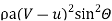

 cos θ =
 (V-u)
(V-u)
Work done per second by the jet on the plate
=
=
=
Consider a jet of water striking a vertical plate at the centre which is hinged at O.
Due to the force exerted by the jet on the plate, the plate swing through some angle about the hinge as shown in fig.
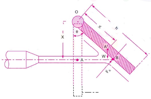
Let x= distance of the centre of Jet from hinge O
Θ= Angle of Swing about hinge
W=weight of plate acting at C.G. of the plate
The dotted line shows the position of the plate, before the jet strikes the plate. The point A on the plate will be of A' after the jet strikes the plate.
The distance OA= OA'=x
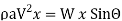
Let the weight of the plate is acting at A'. When the plate is in equilibrium after the jet strikes the plate. The moment of all the forces about the hinge must be zero.
Two force are acting on the plate
1.Force due to Jet of water, normal to the plate
Where  = angle between jet and plate
= (90- )
)
2.Weight of the plate, W
Moment of force  about hinge

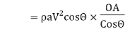

= 
Moment of weight W About hinge
= W × OA’ sin θ
= W×  θ
θ
For equilibrium of the plate

1.11.1. Force exerted by a jet on stationary curved plate
A) Jet strikes the curved plate at the centre.
Let a Jet of water strikes a fixed curved plate at the centre as shown in Fig.
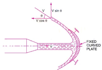
The Jet after striking the plate, comes out with the same velocity. If the plate is smooth and there is no loss of energy due to impact of the jet, in the tangential direction of the curved plate.
The velocity at outlet of the plate can be resolved into two components, one in the direction of jet and other perpendicular to the direction of the jet.
Component of velocity in the direction of jet
=  θ
θ
Component of velocity perpendicular to the jet
=  θ
θ
Force exerted by the jet in the direction of jet,
 =
= × [
× [
 = Initial Velocity in the direction of jet=
 = Final velocity in the direction of jet=
  θ
θ
 =
= θ
θ =
=  θ
θ
=  θ
θ

Similarly,
 =initial velocity in the direction of
 =final velocity in the direction of
  θ
θ
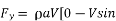 θ] =
θ] =  θ
θ
Negative sign means that forces acting in the downward direction. In this case the angle of deflection of the jet = (180°- θ)
B) Jet strikes the curved plate at one end tangentially when the plate is symmetrical.
Let the jet strikes the curved fixed plate at one end tangentially as shown in fig.
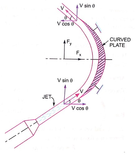
Let the curved plate is symmetrical about x-axis
Then the angle made by the tangents at the two ends of the plate will be same.
Let V= velocity of Jet of water
Θ= angle made by jet with x-axis at inlet tip of the curved plate will be equal to V.
The forces exerted by the jet of water in the directions of x and y are

=  θ
θ θ)
θ)
= θ
θ θ]
θ]
=  θ
θ

=  θ
θ θ
θ
C) Jet strikes the curved plate at one end tangentially when the plate is unsymmetrical.
When the curved plate is unsymmetrical about x axis, then angle made by the tangents drawn at the inlet and outlet tips of the blade with x-axis will be different.
Let, θ = angle made by tangent at inlet tape with x-axis
 = Angle made by tangent at outlet tape with x-axis
The two components of the velocity at inlet are
 θ and
θ and  θ
θ
The two components of the velocity at outlet are

The forces exerted by the jet of water in the directions of x and y are
=  θ
θ )
)
= θ
θ
 ]
]
=  θ
θ
 ]
]
=  θ
θ

=  θ
θ ]
]
Force on the curved plate when the plate is moving in the direction of jet.
Let a jet of water strikes a curved plate of the centre of the plate which is moving with uniform velocity in the direction of the jet as shown in fig.
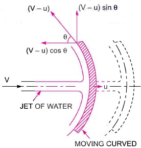
Let V=Absolute velocity of jet
a = Area of jet
u =Velocity of the plate in direction of the jet
Relative velocity of the jet of water=V-u
If plate is smooth and the loss of energy due to impact of jet is zero, then the velocity with which the jet will be leaving the curved vane =V - u
This velocity can be resolved into two components one in the direction of the jet and other perpendicular to the direction of the jet and other perpendicular to the direction of the jet.
Components of velocity in the direction of the jet = - (V-u) cos 
Component of velocity in the direction perpendicular to the direction of the jet = (V-u)
Mass of the water striking the plate
= velocity with which jet strikes the plate
 (V- u)
Force exerted by jet of water on the curved plate in the direction of the jet

=

=
Work done by jet on the plate per second
= Distance travelled per second in direction of x
= u
u
=
=
The force exerted by a jet of water on a single moving plate is not practically feasible. This case is only a theoretical one.
In actual practice a large number of plates are mounted on the circumference of a wheel at a fixed distance apart as shown in fig.
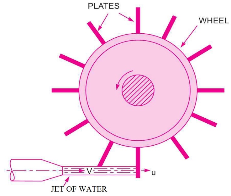
The jet strikes a plate. Due to the force exerted by the jet on the plate wheel starts moving at a constant speed.
Let V=Velocity of jet
d=distance of jet
a=cross sectional area of jet =
u=Velocity of vane
In this case mass of water coming out from the nozzle per second is always in contact with the plates, when all the plates are considered. Hence mass of water per second striking the series of plate =
Also the jet strikes the plate with a velocity (V-u)
After striking, the jet moves tangential to the plate and hence the velocity component in the direction of motion of plate is equal to zero.
The force exerted by the jet in the direction of motion of plate.
 =Mass per second [initial velocity – Final velocity]
= [(V-u) - 0]
=  (V-u)
(V-u)
Work done by the jet on the series of plate per second
=Force  Distance per second in the direction of force
=
= [V-u] u
Kinetic energy of jet per second
=
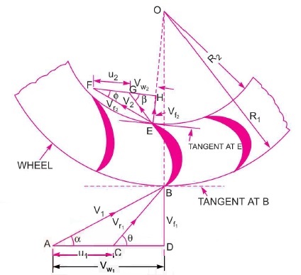
Efficiency =
For a radial curved vane, the radius of the vane at inlet and outlet is different & hence the tangential velocities of the radial vane at the inlet and outlet are not equal.
Consider a series of radial curved vanes mounted on a wheel as shown in fig.
The jet of water strikes the vanes and the wheel start rotating at a constant angular speed
 Radius of wheel at the inlet of vane
 Radius of wheel at the outlet of vane
 = Angular speed of the wheel
Then, 
And 
The mass of water striking per second for a series of vane =
Where a= Area of jet
 Velocity of jet
Momentum of water striking the vanes in the tangential direction per second at inlet= Mass of water per second  Component of V in the tangential direction
=
Similarly momentum of water at outlet per second = Component of
  in the
tangential direction
= (-
(- cos
cos )
)
=
Now angular momentum per second in the inlet
=Momentum at inlet  Radius at outlet
=
Angular momentum per second at outlet
=momentum at outlet  Radius at outlet
= -
Torque exerted by the water on the wheel
T= Rate of change of angular momentum
= [Initial angular momentum per second – Final angular momentum per second]
= -(-
-(-
= +
+
Work done per second on the wheel
=Torque  Angular velocity
=T
= +
+
= +
+
= +
+
If angle  in fig. is on obtuse angle then work done per second will be given as
 -
-
General expression for the work done per second on the wheel
if the discharge is radial at outlet then  & work done becomes as
Efficiency of the radial curved vane  =
=
=
=
=
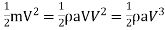
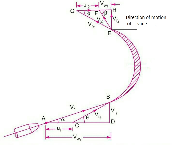
1.14 Velocity triangles and their analysis
Fig. shows a jet of water strikes a moving curved plate (vane) tangentially at one of its tips.
Let
 =Velocity of the jet of inlet
 =Velocity of the vane at inlet
 =Relative velocity of jet and vane of inlet
 = Guide blade angle
(Angle between the direction of jet and direction of motion of the plate)
 Angle made by the relative velocity
  with direction of motion at inlet (vane angle at inlet )
 =The components of velocity of jet
  in the direction of motion and perpendicular to direction of motion of the vane respectively.
 = Whirl velocity at inlet
 = Flow velocity at inlet
 =Velocity of jet leaving the vane or velocity of the jet at the outlet of vane
 = Velocity of the vane at outlet
 =Relative velocity of the jet with respect to the vane
 =Angle made by the velocity
  with direction of motion of the vane at outlet
 =Vane angle at outlet
 =Whirl velocity of outlet
 =Velocity of the flow at outlet
The triangles ABD and EGF are called the velocity triangles of inlet and outlet
Velocity triangle at inlet


Then BD= Velocity of the flow at inlet=
AD=Velocity of the whirl at inlet-
Angle BCD = Vane angle of the inlet 
2. Velocity triangle of outlet
If vane surface is assumed to be very smooth, the loss of energy due to friction will be zero. The water will be gliding over the surface of the vane with relative velocity equal to  and will come out of the vane with the relative velocity
  . Which means
  . And also relative velocity at outlet and EG=
 . From G draw a line GF in the direction of vane at outlet & equal to u2 , the velocity of vane at outlet. Join EF. Then EF represents the absolute velocity of the jet at outlet in magnitude & direction. From E draw vertical line EH to meet the line GF produced at H. Then
EH=Velocity of flow of outlet =
FH=Velocity of whirl at outlet =
 Angle of vane of outlet
 =Angle made by
  with the direction of motion of vane at outlet.
If the vane is smooth and is having velocity in the direction of motion at inlet and outlet equal then we have  = u = velocity of vane in the direction of motion

Mass flow of water striking vane= ----(1)
Where a =Area of jet of water
 Relative velocity of inlet
Force exerted by the jet in the direction of motion
 =Mass of water striking per second
 [initial velocity- final velocity] ----(2)
But initial velocity with which jet strikes the vane =
The component of this velocity in the direction of motion=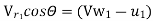
Similarly, the component of relative velocity at outlet in the direction of motion = 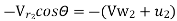
Substituting the equation (1) and all above value of velocity in equation 2
 [(
[( -
- -[-
-[-
= [(
[( -
- +
+
=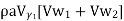 , because
  …….. 3
Equation (3) is true only when angle  shown in fig is an acute angle.
If  =
=  , the
, the  Then equation (3) becomes as
 [
[
If  is an obtuse angle, the expression for
  will become
 [
[
Thus in general,  is written as
 [
[
Work done per second on the vane by the jet
=Force  velocity
=
= [
[
Work done per second per unit weight of fluid striking per second
= 
= 
= 
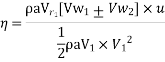
Efficiency of jet 
=
= 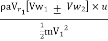
Where m=mass of fluid per second in the jet
 Initial velocity
Numerical
1. A 7.5cm diameter jet having a velocity of 30 m/s strikes a flat plate , the normal of which inclined at  to the axis of the jet .Find the normal pressure on the plate.
Also determine the power and efficiency of the jet when the plate is moving.
Diameter of the jet = 7.5cm=0.075m
Area of the jet = (0.75)2 =0.04417
Angle between the jet and plate =  =
=
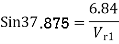
Velocity of jet 

= 
2. When the plate is moving with a velocity  and away from the jet the normal force on the plate
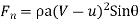
= 
 496.9N
Work done per second by the jet = force in the direction of jet x Distance moved by the plate
in the direction of jet/sec 
= 496.9 x 15= 7453.5 Nm/s
Power in kW= =
=  = 7.453 KW
Efficiency of the jet =
= 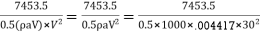
= 0.1249=12.5%
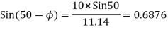
2. A jet of water having a velocity of 20m/s strikes a curved vane which is moving with a velocity of 10m/s . The jet makes an angle of  with the direction of motion of vane at inlet and leaves at an angle of
  to direction of motion of motion of vane an outlet. Calculate:
Given


 in triangle ABD we have
Where 

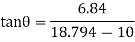

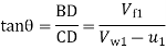
From triangle ABC

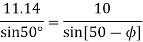
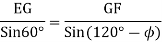
From triangle EFG applying sine rule
We have 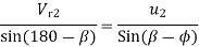

Work done per second per unit weight of the water striking the vane per second
= 
Where 


Work done per unit weight of water
= 
3. A jet of water of diameter 50 mm, having a velocity of 20m/s strikes a curved vane which is moving with a velocity of 10m/s in the direction of the jet. The jet leaves the vane at an angle of 60 to the direction of motion of vane at outlet determine:
1) The force exerted by the jet on the vane in the direction of motion.
2) Work done per second by the jet.
Diameter of the jet d= 50mm=0.05 m
Area, a=
Velocity of jet ,
Velocity of vane, 
As jet and vane are moving to the same direction 
Angle made by the leaving jet with the direction of motion 

From figure we have

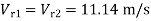
= 20-10 =10m/s
 = 20m/s
 =10m/s
Now in  EFG, EG =
 =10m/s
GF= =10m/s

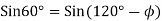
From sine rule we have,
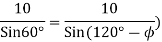
Now ,  = HF - GF=GH
= -
- cos
cos =10 -10
 cos
cos =10 - 5 = 5 m/s
The force exerted by the jet on the vane in the direction of motion
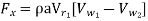 ( negative sign as
  is an obtuse angle)
= 1000 0.001963
 10[20 - 5] = 294.45N
Work done per second by the jet
 u=294.45
 10=2944.5 N m/s
=2944.5 W


