Measurement standards and Design of gauges
Types of standards
To facilitate measurement at different locations depending upon the relative importance of standard, they are divided into the following four groups:
2. Secondary standards
3. Tertiary standards
4. Working standards
Systematic error
2. Ambient Conditions
3. Deformation of Workpiece
4. Avoidable Errors
These include the following:
b. Reading errors
c. Errors due to parallax effect
d. Effect of misalignment
e. Zero errors
Radom error
1. Presence of transient fluctuations in friction in the measuring instrument
2. Play in the linkages of the measuring instruments
3. Error in operator’s judgement in reading the fractional part of engraved scale divisions
4. Operator’s inability to note the readings because of fluctuations during measurement
5. Positional errors associated with the measured object and standard, arising due to small variations in setting.
Systematic error | Random error |
These errors are consistent and | These errors are non-consistent and accidental in nature. |
Not easy to detect | Easy to detect |
They occur due to improper conditions or methods of measurements. | They are inherent in the measuring system or measuring instruments. It is assumed that random error occurrence is bound to be there. |
Cannot be eliminated by repeated measurements | Can be minimized by repeated measurements |
Can be assessed easily | Statistical analysis required |
Minimization of systematic errors increases the accuracy of measurement | Minimization of random errors increases repeatability and hence precision of the measurement |
Calibration helps reduce systematic errors | Calibration has no effect on random errors |
Characterization not necessary | Characterized by mean, standard deviation, and variance |
Statistical methods do not operate on the systematic errors. | Statistical methods only operate on the random errors. |
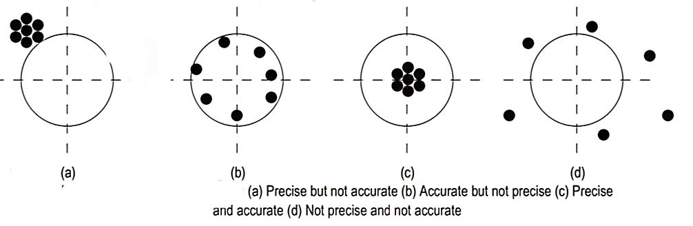
Accuracy
Precision
Accuracy | Precision |
Accuracy is the agreement of measured value with the true value of measured quantity. | Precision is the repeatability of measuring process. |
Accuracy is concerned with true value. | Precision is concerned with mean value. Precision has no concern with true value. |
It is difficult and expensive to have good accuracy. | It is much easier and cheaper to achieve precision than to achieve great accuracy. |
High accuracy cannot be obtained with low precision. | High precision can be obtained with low accuracy. |
If true value is 10 mm, then 9.99 mm is more accurate than 9.91 mm. | If true value is 10 mm, and readings obtained are 10.001, 10.002, 10.003, 10.004 and 10.005 mm, then mean value of readings will be 10.003 mm. Therefore, the measurements are said to be precise, because all the readings are very close to their mean value. |
Sensitivity:
Readability:
Repeatability:
Reproducibility:
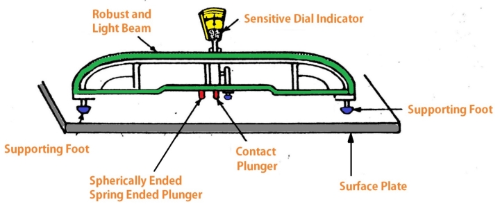
List of components in Beam comparator
Construction of Beam comparator
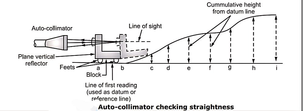
Principle of Beam Comparator
of the surface to be tested.
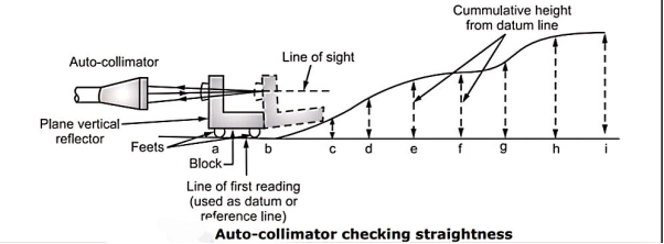
(i) image of cross wires of the collimator appears very near to the center of
eyepiece, and
(ii) linear movement of reflector over the entire length of surface under test is completed.
1 second of arc = 0.000006 mm/mm
Classification of Tolerance
Tolerance can be classified under the following categories:
Unilateral Tolerance

Bilateral Tolerance

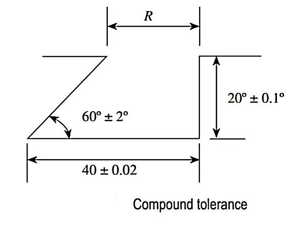
Compound Tolerance
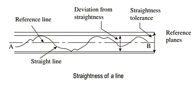
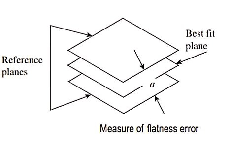
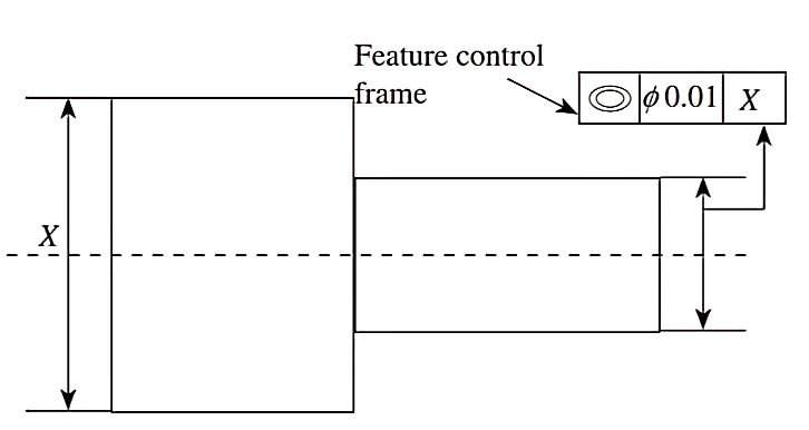
Geometric Tolerance
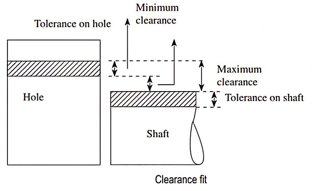
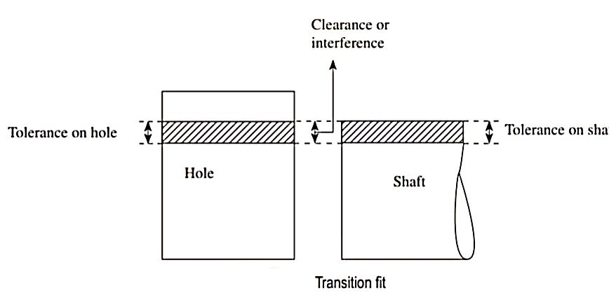
Fits
Limits
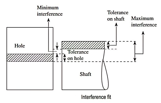
2. Interference fit
3. Transition fit
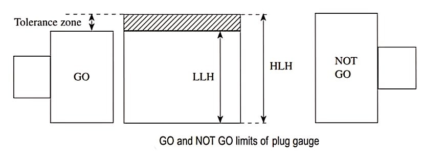
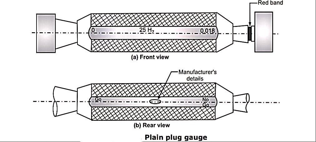
1. Plain plug gauge
2. Plain ring gauges
prevent against corrosion.
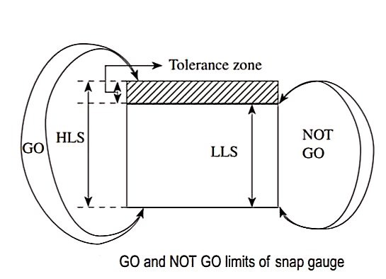
3. Snap gauge
a) Double ended snap gauges: Used to check shaft having diameter in the range of 3 mm to 100 mm.
b) Single ended snap gauges: Used to check shaft having diameter in the range of 100 mm and 250 mm.
4. Limit gauge
The following points must be kept in mind while designing gauges:
1. The form of GO gauges should be a replica of the form of the opposed (mating) parts.
2. GO gauges enable several related dimensions to be checked simultaneously and hence are
termed complex gauges.
3. During inspection, GO gauges must always be put into conditions of maximum impassability.
4. NOT GO gauges check a single element of feature at a time.
5. In inspection, NOT GO gauges must always be put into conditions of maximum passability.
Numericals:
90H8e9
D=√ (80×100)
=89.44mm
i=
=2.071
The fundamental tolerance=IT8=25i
=25×2.07
=51.8 microns
Therefore, the hole limits are

Upper limit of hole = 90+0.052 = 90.052 mm
Lower limit of hole = 90+0 = 90 mm
Fundamental tolerance IT9=40i
=40×2.07
=82.8microns
For e shaft the fundamentals deviation
=
= -69.42 microns
The shaft limits are
=
Upper limit of shaft = 90 - 0.069 = 89.931mm
Lower limit of shaft =90 - 0.152 = 89.848mm
2. Determine the dimensions & tolerance of shaft & hole having size of 30H7f8 fit. IT7 = 16i, IT8 = 25i, D is in step 18 – 30mm, Fundamental deviation for f = -5.5 D0.41
D=
=23.24mm

The fundamental tolerance IT7=16i
=16×1.36
=21.83microns
The hole limits are
=
Upper limit of hole=30+0.021
=30.021mm
Lower limit of hole=30+0
=30mm
Therefore, the hole tolerance is
=30.021-30
=0.0218mm
Fundamental tolerance IT8=25i
=25×1.36
=-34microns
For f shaft the fundamental
=
=
=-20 microns
The shaft limits are
=
Upper limit of shaft
=30-0.02
=29.98mm
Lower limit of shaft
=30-0.054
=29.946mm
The shaft tolerance is
=29.98-29.946
=0.034mm
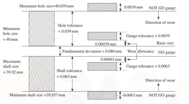
3. Design the general type of GO and NOT GO gauges as per the present British system for a 40mm shaft and hole pair designated as 40 H8/d9, given that


The standard diameter steps for 40 mm shortfall in the range of 30 to 50 mm.
Therefore,
D=
D=38.7928mm
The value of fundamental tolerance unit is given by

For hole quality H8, the fundamental tolerance is 25i.
25i = 25(1.571) = 39.275 μm =0.039275mm≈ 0.039mm
For hole, the fundamental deviation is zero.
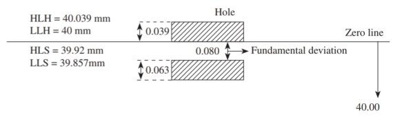
Hence hole limits are as follows:
LLH=40mm
HLH = 40.00+0.039=40.039mm
Hole tolerance = 40.039 – 40 = 0.039mm
For shaft quality d9, the fundamental tolerance is 40i.
40i = 40(1.571) = 62.84 μm = 0.06284mm ≈ 0.063mm
For d shaft, the fundamental deviation is given by 
Therefore, fundamental deviation= 
= 79.9576 μm ≈ -0.07996mm ≈ -0.080mm
Hence, shaft limits are as follows;
HLS = 40 - 0.080 = 39.92mm
LLS=40 - (0.080+0.063) = 39.857mm
Shaft tolerance = 39.92 - 39.857 = 0.063mm
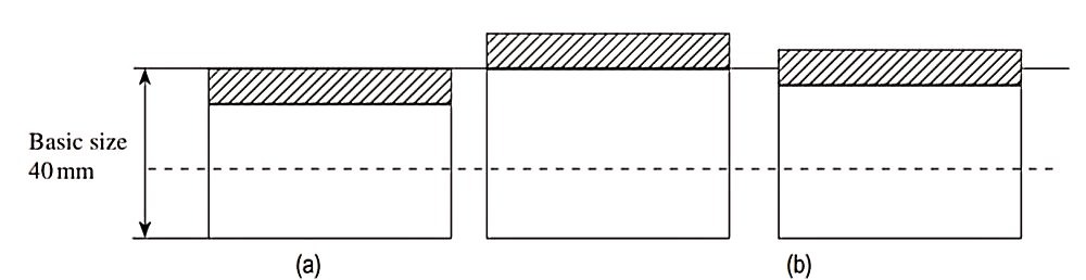
Hence the hole and shaft limits are as follows:
Hole = 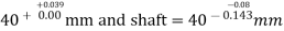
The disposition tolerances is as shown in figure
Assuming gauge tolerance to be 10% of work tolerance,
Gauge tolerance for hole =10% of 0.039=0.0039mm
Where allowance for hole =10% of Gauge tolerance; therefore,
Therefore, wear allowance for hole=10% of 0.0039=0.00039mm
Similarly,
Gauge tolerance for shaft=10% of 0.063=0.0063mm
Wear allowance for shaft=10% of 0.0063=0.00063mm
For hole;
The limits of GO Plug gauge are as follows:
Low limit = basic size + wear allowance
Low limit = 40.00+0.00039 = 40.00039mm
High limit=basic size+ (wear allowance + gauge tolerance)
High limit = 40.00+(0.00039+0.0039) mm
=40.00+(0.00429) = 40.00429mm
Limits of GO plug gauge =
The limits of NOT GO plug gauge are as follows:
Low limit = basic size + fundamental tolerance for hole
Low limit=40.00+0.039=40.039mm
High limit = basic size + (fundamental tolerance for hole+ gauge tolerance)
High limit=40.00+(0.039+0.0039) mm
=40.00+(0.0429) =40.0429mm
Limits of NOT GO plug gauge =
For shaft:
The limits of GO snap goes are as follows:
High limit=basic size - (fundamental deviation + wear allowance)
High limit = 40.00 - (0.080+0.00063) mm
High limit=40.00-(0.08063) = 39.91937mm
Low limit=Basic size - (fundamental deviation + wear allowance +gauge tolerance)
Low limit=40.00 -(0.080+0.00063+0.0063) mm
=40.00 - (0.08693) = 39.91307mm
Limits of GO snap gauge=
Limits of NOT GO snap gauge are as follows:
High limit=basic size - (fundamental deviation + fundamental tolerance)
High limit =40.00 - (0.080 + 0.063) mm
High limit=40.00 - (0.143) = 39.857mm
Low limit = basic size - (fundamental deviation + fundamental tolerance + gauge tolerance)
Low limit=40.00 - (0.080+0.063+0.0063) mm = 39.8507mm
Limits of NOT GO snap gauge = mm
mm
The disposition of gauge tolerances and wear allowance for the GO and NOT GO plug and snap gauge are schematically shown in fig.