Pneumatics – Components, Control Valves and Circuits
The English word pneumatic and its associate noun pneumatics are derived from the Greek “pneuma” meaning breath or air.
“Pneumatics may be defined as a branch of engineering science which deals with the study of the behavior and application of compressed air.”
“Pneumatics can also be defined as the branch of fluid power technology that deals with the generation, transmission, and control of power using pressurized air.”
5.1.1 Differences between hydraulic and pneumatic systems.
One of the main differences between the two systems is that in pneumatics, the air is compressible. In hydraulics, liquids are not. The other two distinct differences are given below.
Pneumatic Systems
These systems have two main features:
Hydraulic Systems
These systems also have two main features:
5.1.2 Components of the Pneumatic System
The pneumatic system carries power by employing compressed gas generally air as a fluid for transmitting the energy from an energy-generating source to an energy – use point to accomplish useful work.
The figure shows the simple circuit of a pneumatic system with basic components.
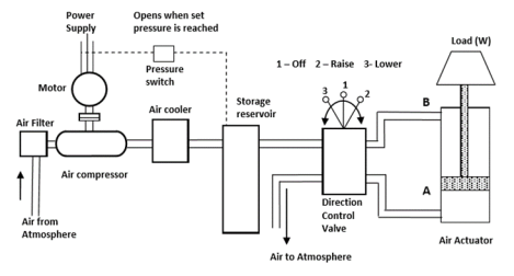
Fig. Components of the Pneumatic System
Position of the valve is as follows
Functions of components
Advantages of Pneumatic system
Disadvantages of Pneumatic systems
5.1.3 Comparison between Hydraulic and Pneumatic System
Sr. No. | Hydraulic System | Pneumatic System |
1 | It employs a pressurized liquid as fluid | It employs a compressed gas usually air as a fluid |
2 | The oil hydraulics system operates at pressures up to 700 bar. | Pneumatics systems usually operate at 5 to 10 bar. |
3 | Generally designed for closed systems | Pneumatic systems are usually designed as an open system |
4 | The system gets slow down of leakage occurs | Leakage does not affect the system much more |
5 | Valve operations are difficult | Easy to operate the valves |
6 | Heavier in weight | Light in weight |
7 | Pumps are used to provide pressurized liquids | Compressors are used to provide compressed gas |
8 | The system is unsafe to fire hazards | The system is free from fire hazards |
9 | Automatic lubrication is provided | Special arrangements for lubrication needed. |
“A Compressor is a machine that compresses the air or another type of gas from a low inlet pressure (usually atmospheric pressure) to a higher desired pressure level.”
The compressor increases the pressure of the air by reducing its volume. The work required for increasing the pressure of air is available from the prime mover driving the compressor. Generally, electric motor, internal combustion engine or steam engine, turbine, etc. are used as prime movers. Compressors are similar to fans and blowers but differ in terms of pressure ratios.
5.2.1 Classification
(a) Based on the principle of operation:
Based on the principle of operation compressors can be classified as.
I] Positive Displacement Compressors
In positive displacement compressors, the compression is realized by displacement of solid boundary and preventing fluid by solid boundary from flowing back in the direction of the pressure gradient. Due to solid wall displacement, these are capable of providing quite large pressure ratios. Positive displacement compressors can be further classified based on the type of mechanism used for compression. These can be
i] Reciprocating Type Positive Displacement Compressors
ii] Rotary type positive displacement compressors
II] Non-positive Displacement Compressors
Non-positive displacement compressors also called a steady flow compressor to use dynamic action of solid boundary for realizing pressure rise. Here the fluid is not contained indefinite volume and subsequent volume reduction does not occur as in case of positive displacement compressors.
Non-positive displacement compressors may be of “axial flow type” or “centrifugal type” depending upon the type of flow in the compressor.

Fig. Classification of Compressor
(b) Based on a number of stages:
Compressors may also be classified on the basis of a number of stages.
Generally, the number of stages depends upon the maximum delivery pressure. Compressors can be single-stage or multistage. Normally maximum compression ratio of 5 is realized in single-stage compressors. For compression ratio more than 5 the multistage compressors are used.
Type values of maximum delivery pressures generally available from a different type of compressor are,
(c) Based on Capacity of compressors:
Compressors can also be classified depending upon the capacity of Compressor or air-delivered per unit time.
Typical values of capacity for different compressors are given as;
(d) Based on the highest pressure developed:
Depending upon the maximum pressure available from compressors they can be classified as low-pressure, medium pressure, high-pressure, and super high-pressure compressors. Typical values of maximum pressure developed for different compressors are as under:
5.3.1 The piston Compressor
The piston compressors are by far the most common type of compressor, and a basic single cylinder form is shown in Figure.
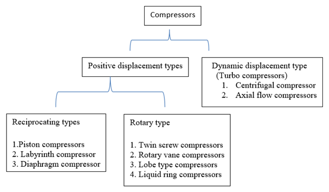
Fig. Single Cylinder The piston Compressor
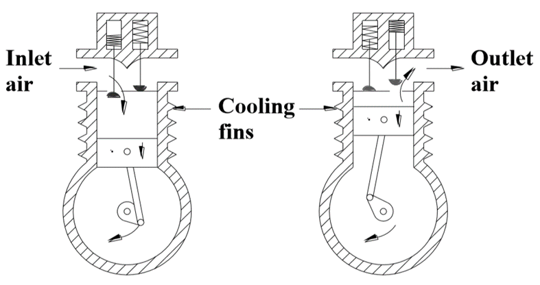
Fig. Multi-stage The piston Compressor
5.3.2 Screw Compressor
One rotary compressor, known as the dry rotary screw compressor, is shown in Figure and consists of two intermeshing rotating screws with minimal (around 0.05 mm) clearance.
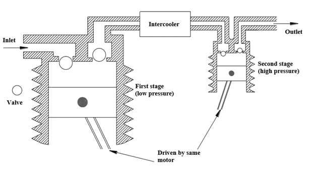
Fig. Screw Compressors
5.3.3 Rotary Vane Compressor
The vane compressor, shown in Figure operates on similar principles to the hydraulic vane pump.
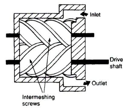
Fig. Vane Compressor
5.3.4 Lobe Compressor
The lobe compressor is shown in figure
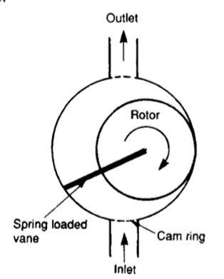
Fig. Lobe Compressor
5.3.5 Non-positive Displacement Compressors
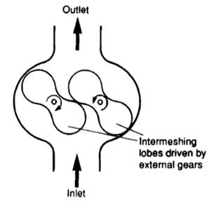
Fig. Non-positive Displacement Compressors
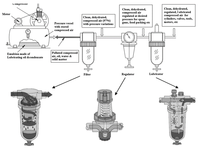
“The purpose of the fluid conditioners is to make the compressed air more acceptable and suitable fluid medium for the pneumatic system as well as the operating personal.”
The following fluid conditioners are used in pneumatic systems
1. Air Filters
2. Air Regulators
3. Air Lubricator
5.4.1 Air Filters
The purpose of the air filter is to clean the compressed air of all impurities and any condensate it contains.
The function of air filters
Filters are available in wide range starting from a fine mesh wire cloth (which strains heavy foreign particles) to elements made of synthetic material (which removes very small particles)
Usually, inline filter elements can remove contaminants in the 5-50 micron range.
The construction of a typical cartridge type filter along with graphical symbols is shown in Figure
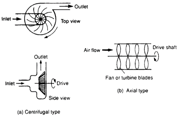
Fig. Typical Air Filter
5.4.2 Air Regulator
Types of Air Pressure Regulator
There are two types of Pressure regulators
Diaphragm type regulator is commonly used in the Industrial pneumatic system. There are two types of diaphragm type regulator
Relieving or Venting Type Pressure regulator
A Relieving type pressure regulator is shown in Figure
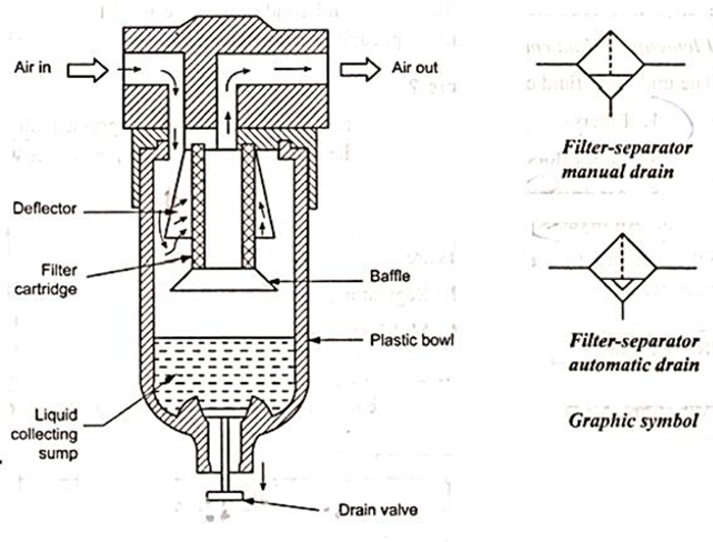
Fig. Venting type pressure regulator
Non-Relieving or Non-Venting Type Pressure regulator
The figure shows the non –relieving venting type pressure regulator.
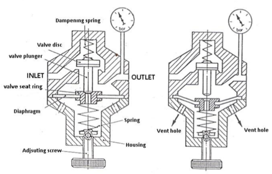
Fig. Non-venting type pressure regulator
5.4.3 Air Lubricator
The function of air lubricator is to add a controlled amount of oil with air to ensure proper lubrication of internal moving parts of pneumatic components. Lubricants are used to
The lubricator adds the lubricating oil in the form of a fine mist to reduce the friction and wear of moving parts of pneumatic components such as valves, packing used in air actuators
Excessive lubrication is undesirable. Excessive lubrication may result in
Schematic diagram of air lubricator is shown in Figure
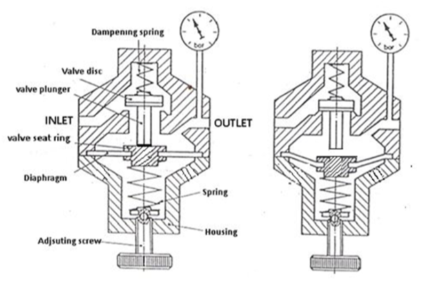
Fig. Air Lubricator
5.4.4 Filter Regulator Lubricator Unit (FRL Unit) /Service Unit
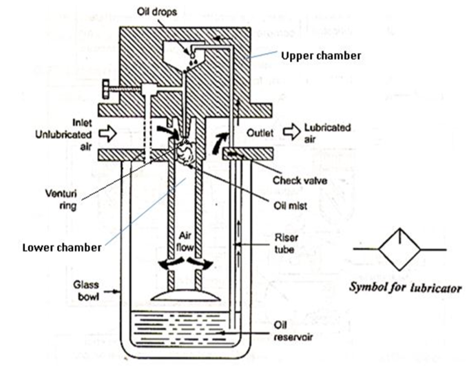
Fig. Installation of FRL unit
The combination of filter, regulator, and lubricator is called FRL unit or service unit.
Figure (a) gives a three-dimensional view of the FRL unit. Figure (b) gives a detailed symbol of the FRL unit. Figure (c) gives a simplified symbol of the FRL unit.
Pneumatic air silencers, also commonly called pneumatic mufflers, are a cost-effective and simple solution to reduce noise level and unwanted discharge of contaminants from pneumatics.
Figure 1 shows examples of common pneumatic silencers.
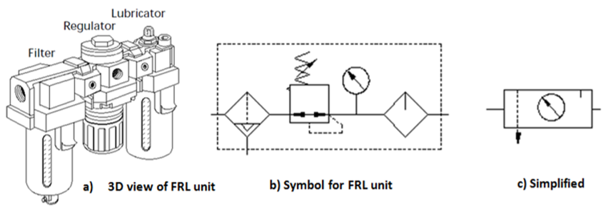
Fig. Examples of Mufflers
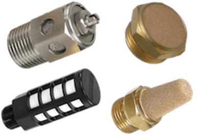
Fig. Symbol of muffler
The function of the dryer is to lower the dew point of the compressed air by removing the moisture from it. For simple applications, to remove excess humidity, we need a simple aftercooler, an air receiver, and a filter with condensate traps.
Types of Dryer
Generally, four basic types of air dryers are used in Industries.
- Absorption type dryer
Schematic diagram of the absorption dryer is shown in Figure
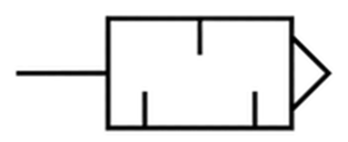
Fig. Absorption Dryer
Advantages of Absorption dryer
Disadvantages of Absorption dryer
5.6.2 Adsorption type dryer
Adsorption is a physical process of moisture removal on the porous surface of certain granular materials.
The figure shows the various parts of the adsorption dryer.
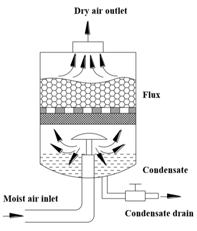
Fig. Adsorption Dryer
5.6.3 Refrigerated Dryer
The layout of a typical refrigerated air dryer is shown in Figure
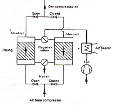
Fig. Refrigerated Dryer
The function of the directional control valve is to control the direction of flow in the pneumatic circuit. DCVs are used to start, stop, and regulate the direction of airflow and to help in the distribution of air in the required line.
5.7.1 Types of DCV
Directional valves control the way the air passes and are used principally for controlling commencement, termination, and direction of airflow. The different classification scheme of the pneumatic cylinders are given below
1. Based on construction
- Ball seat valve
- Disc seat valve
- Diaphragm Valves
- Longitudinal slide valve - Suspended spool valves
- Rotary spool valves
2. Based on the number of ports
3. Based on methods of actuation
4. Based on the Size of the port
Size refers to a valve’s port size. The port sizes are designated as M5, G1/8, and G1/4, etc. M refers to Metric thread, G refers to British standard pipe (BSP) thread.
5. Based on mounting styles
5.7.2 Poppet Direction Control Valves
There are three different types of poppet valves
A] Ball seat valve.
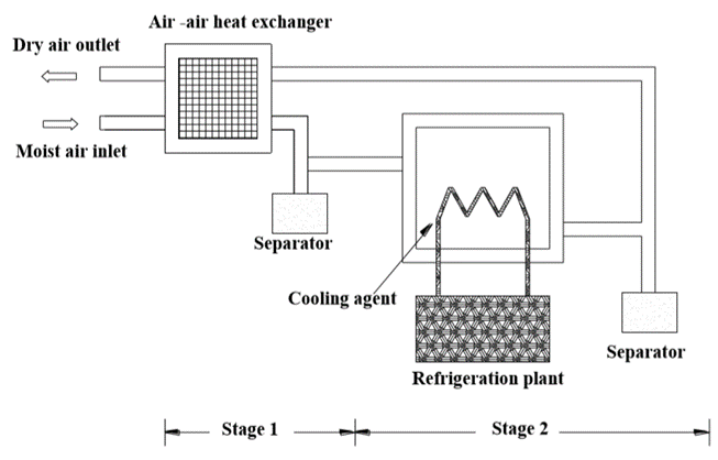
Fig. 2/2 Ball seat poppet valve
B] Disc seat poppet valve
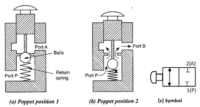
Fig. Disc seat poppet valve
C] Diaphragm valves
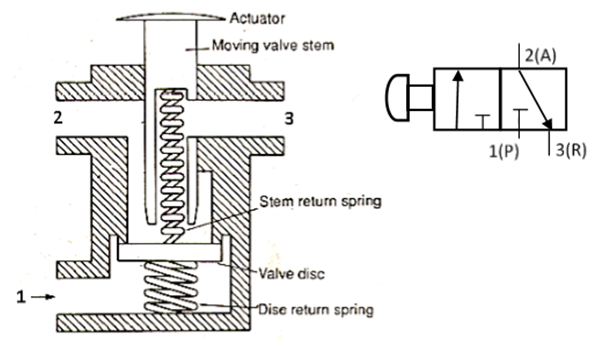
Fig. Diaphragm Valve
5.7.3 Spool Direction Control Valve
then the valve is actuated then port 2 and 1 are connected and port 3 is blocked.
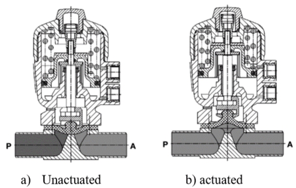
Fig. 3/2 Direction Control Valve (Normally Closed)
B. Pneumatically actuated 3/2 DCV
The cross-sectional views of pneumatically actuated NC type 3/2 DCV in normal position and actuated positions are shown in Figure
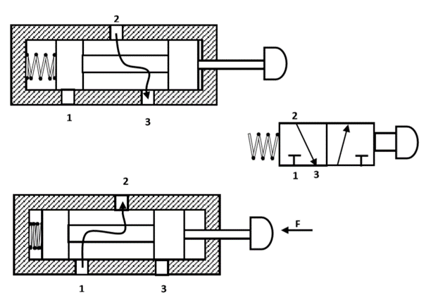
Fig. 3/2 DCV (Pneumatically Actuated)
Pneumatically actuated valves have the following advantages
C. Pneumatically Actuated 4/2 DCV
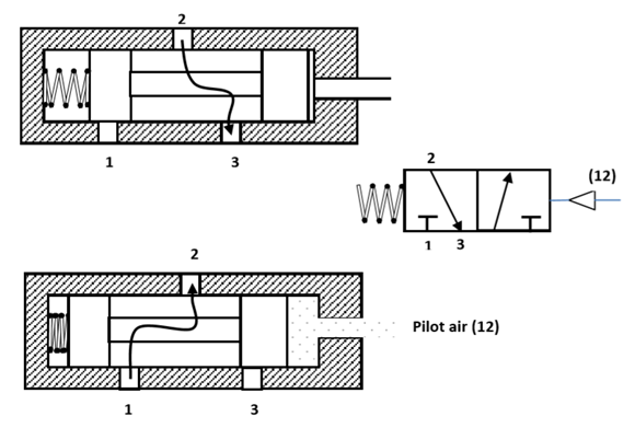
Fig. 4/2 DCV
D. Suspended Disc Direction Control Valves
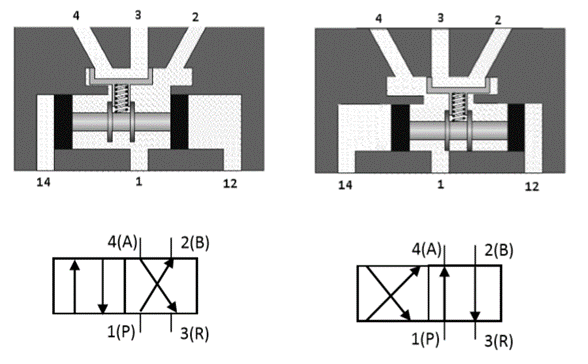
Fig. 4/2 DCV (suspended disc type)
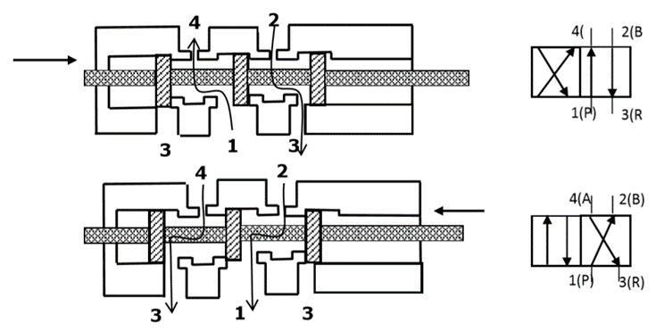
Fig. 5/2 DCV (suspended disc type)
Advantages
Disadvantages
E. Rotary valves
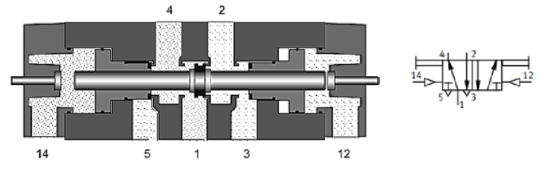
Fig. Parts of Rotary Spool DCV
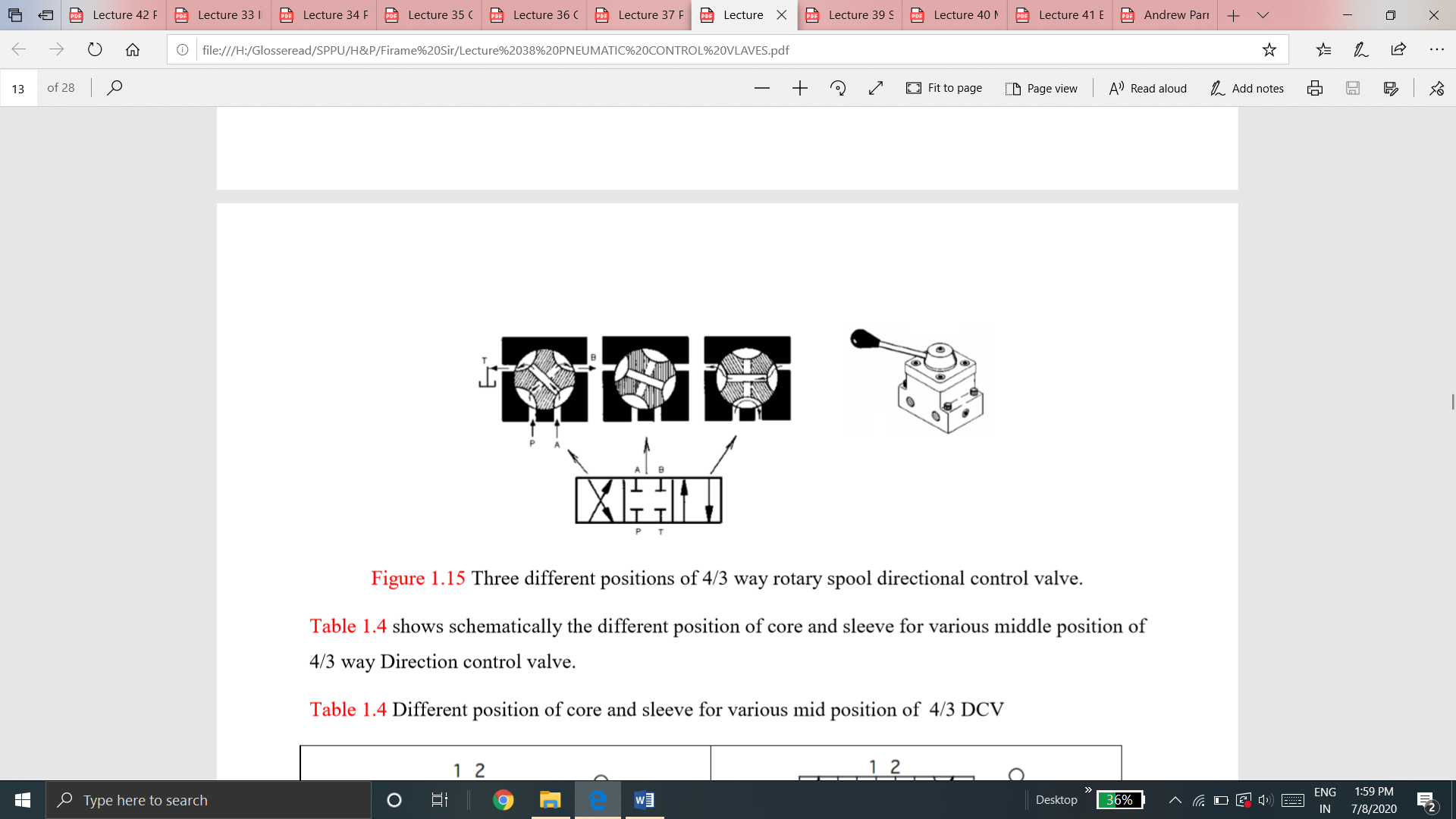
The figure below shows three different positions of the core when the handle is rotated. The leftmost envelope of DCV connects P to B and A to T. Middle envelope of DCV blocks all ports. The rightmost envelope of DCV connects P to A and T to B.
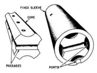
Fig. Different positions of 4/3 way rotary spool DCV
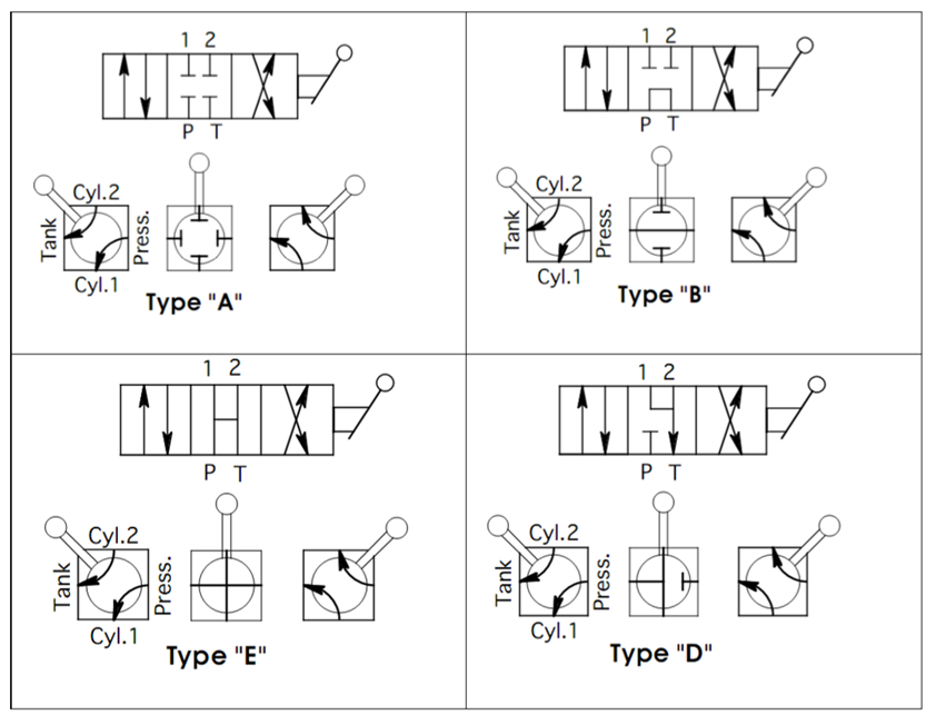
The table shows schematically the different positions of core and sleeve for various middle positions of 4/3 way Direction control valve.
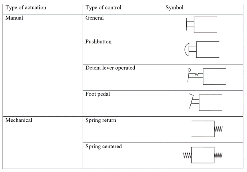
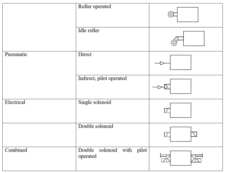
5.7.4 Method of Actuation
The methods of actuation of pneumatic directional control valves depend upon the requirements of the task.
Some basic methods of Actuations are given below
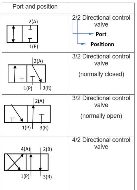
5.7.5 ISO DESIGNATION OF DIRECTION CONTROL VALVES
Valves are represented by symbols because actual construction is quite complex. A symbol specifies the function of the valve, method of actuation, no of ports, and ways. Pneumatic symbols have been standardized in ISO 1219-1:2006. (Fluid power systems and components – Graphic symbols and circuit diagram). Another standard ISO 1219-2:1995 establishes the rules for drawing diagrams of fluid power systems using symbols from ISO 1219-1. Port designations are described in ISO 5599.
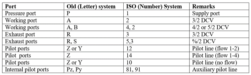
Port markings: As per the ISO 5599, ports are designated using a number system. Earlier, a letter system was used to designate a port. The table below gives port markings.
Ports and position: DCVs are described by the number of port connections or ways they control. For example Two way, three-way, four-way valves. Table 1 shows the Port markings of DCVs and the Table below shows commonly used DCVs with old and new designations.
Non-return valves permit the flow of air in one direction only, the other direction through the valve being at all times blocked to the airflow. Mostly the valves are designed so that the check is additionally loaded by the downstream air pressure, thus supporting the non-return action.
Among the various types of non-return valves available, those preferentially employed in pneumatic controls are as follows
5.8.1Check Valve
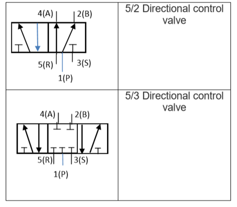
Fig. Check Valve
5.8.2 Shuttle Valve
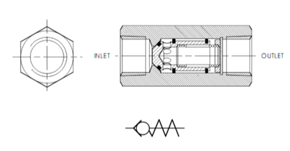
Fig. Shuttle valve
5.8.3 Quick Exhaust Valve
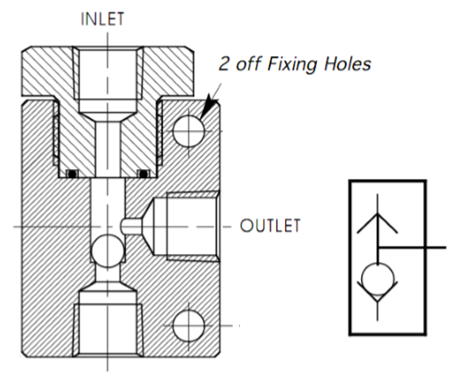
Fig. Quick Exhaust Valve
The construction and operation of a quick exhaust valve are shown in Figure.
Forward Motion: During forward movement of the piston, compressed air is directly admitted behind the piston through ports 1 and 2 Port 3 is closed due to the supply pressure acting on the diaphragm. Port 3 is usually provided with a silencer to minimize the noise due to exhaust.
Return Motion: During the return movement of the piston, exhaust air from the cylinder is directly exhausted to the atmosphere through opening 3 (usually larger and fitted with silencer). Port 2 is sealed by the diaphragm. Thus exhaust air is not required to pass through long and narrow passages in the working line and final control valve
Typical applications of quick exhaust valve for single-acting and double-acting cylinders are shown in Figure.
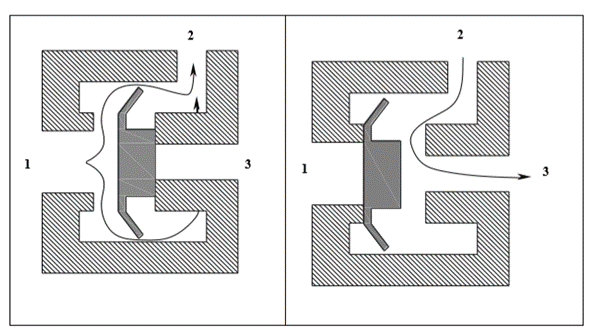
Fig. Application of Quick Exhaust Valve
5.8.4 Two Pressure Valve
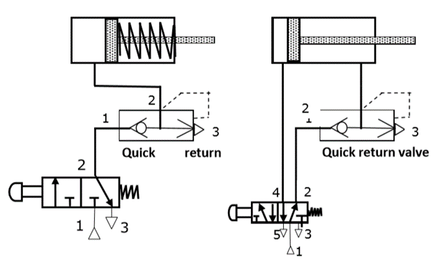
Fig. Two pressure valve
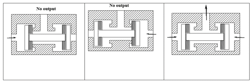
Fig. Time Delay Valve
- On –delay timer
In on-delay timer, the 3/2 DCV is actuated after a delay with reference to the application of the pilot signal and is rest immediately on the application of the pilot signal.
2. Off – delay timer
In off delay timer, the 3/2 DCV is actuated immediately on the application of the pilot signal and is reset only after a delay with reference to the release of the pilot signal.
Pneumatic timers can also be classified according to the type of pneumatically actuated 3/2 DCv as:
1) Time delay valve, NC type
It can be seen that 3/2 DCV operates in the on delay mode permanently. But, in some designs, the valve can be operated in the off-delay mode by connecting the check valve in the reverse direction. For this purpose, the ports of the throttle check valve should be brought out.
2) Time delay valve, NO type.
The construction and function of an on-delay timer (NO) type are similar to that of an on-delay timer (NC) type except for the type of 3/2 DCV valve. In the on-delay valve (NO) type, a 3/2 DCV (NO) type is used whereas in the on-delay timer (NC) type, a 3/2 DCV (NC) type is used.
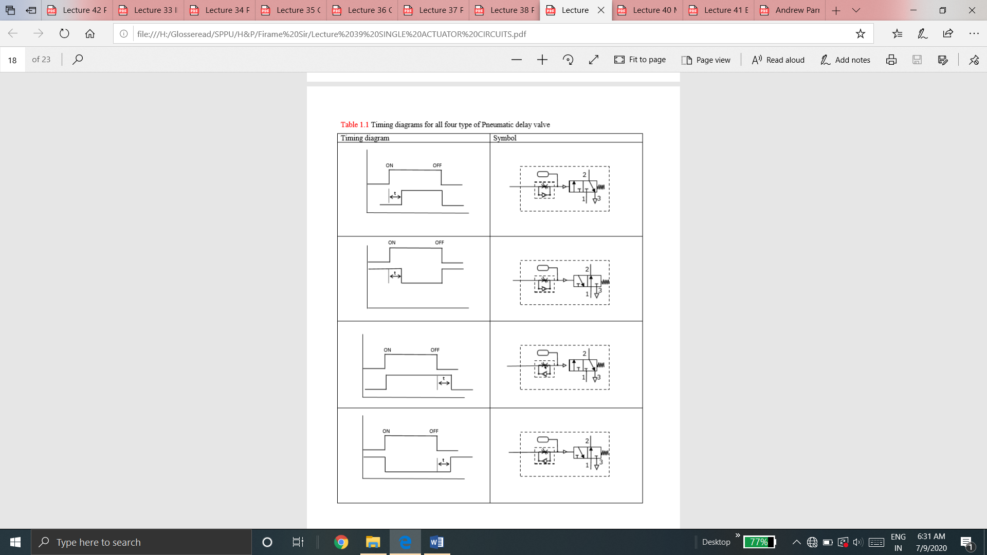
Timing diagrams for all four type of Pneumatic delay valve is given in Table
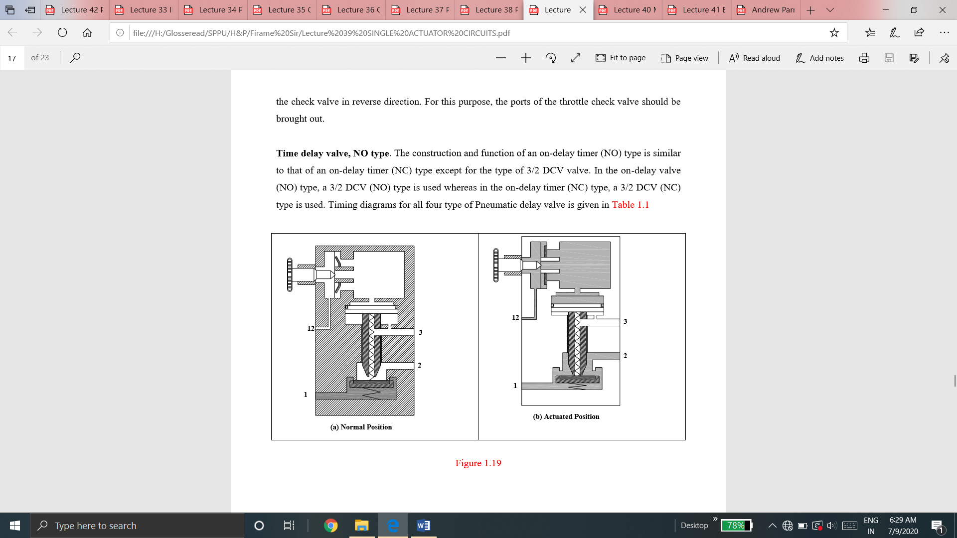
Fig. Timing Diagrams
Pneumatic actuators are the devices used for converting pressure energy of compressed air into mechanical energy to perform useful work.
Actuators are used to perform the task of exerting the required force at the end of the stroke or used to create displacement by the movement of the piston. The pressurized air from the compressor is supplied to the reservoir. The pressurized air from storage is supplied to the pneumatic actuator to do work.
Types of Pneumatic Actuators
Pneumatic cylinders can be used to get linear, rotary and oscillatory motion. There are three types of pneumatic actuator: they are
i) Linear Actuator or Pneumatic cylinders
ii) Rotary Actuator or Air motors
iii) Limited angle Actuators
Pneumatic cylinders /Linear actuators
Pneumatic cylinders are devices for converting the air pressure into linear mechanical force and motion. The pneumatic cylinders are used for single-purpose applications such as clamping, stamping, transferring, branching, allocating, ejecting, metering, tilting, bending, turning, and many other applications.
The different classification scheme of the pneumatic cylinders are given below
5.10.1 Based on the application for which cylinders are used
5.10.2 Based on the cylinder action
A) Single-acting cylinders.
Schematic diagram of a single-acting cylinder is shown in Figure
Fig. Single-acting Cylinder
There are varying designs of single-acting cylinders including:
i) Diaphragm cylinder
The schematic diagram of the diaphragm cylinder is shown in Figure.
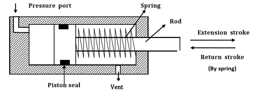
Fig. Diaphragm Cylinder
ii) Rolling diaphragm cylinder
Schematic diagram of Rolling diaphragm cylinder is shown in Figure
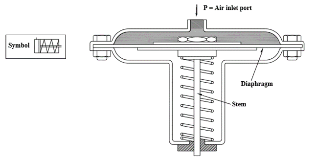
Fig. Rolling Diaphragm Cylinder
iii) Gravity Return Single-acting Cylinder
The figure shows gravity return type single-acting cylinders
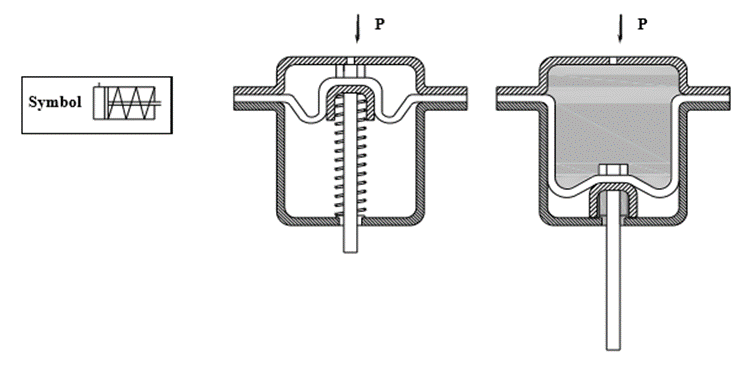
Fig. Gravity return Single-acting Cylinder
iv) Spring Return Single-acting Cylinder
Spring return single-acting cylinder is shown in Figure
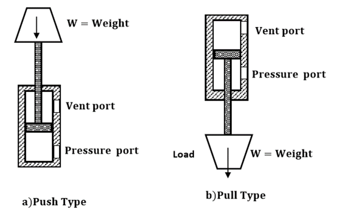
Fig. Spring return single-acting cylinder
B) Double-acting cylinders.
Construction diagram of the double-acting cylinder is shown in Figure
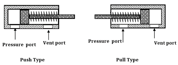
Fig. Construction of double-acting cylinder
There are two types of double-acting cylinders.
i) Double-acting cylinder with the piston rod on one side.
ii) Double-acting cylinder with the piston rod on both sides
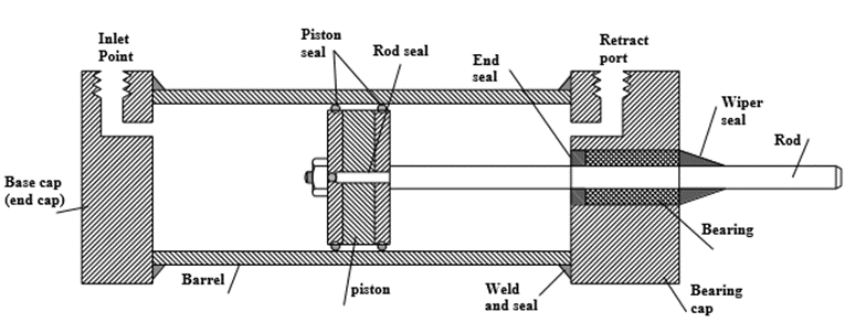
Fig. Double-acting Cylinder with the piston rod on one side
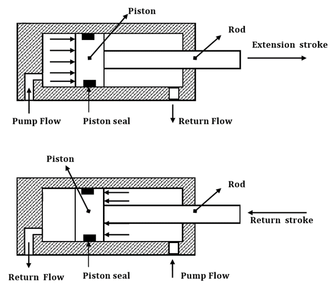
Fig. Double-acting Cylinder with the piston rod on both side
5.10.3 Based on the cylinder’s movement
5.10.4 Based on the cylinder’s design
A) Telescopic Cylinder
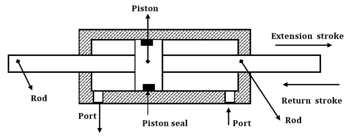
Fig. Telescopic Cylinder
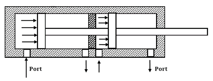
B) Tandem Cylinder
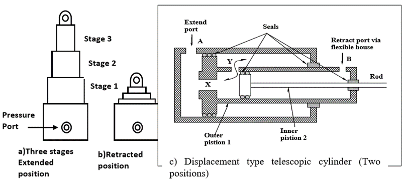
Fig. Tandem Cylinder
5.10.5 Graphical Symbol of Cylinders
Speed regulation is achieved by use of flow control valve. Just like in hydraulic system, speed of cylinder can be regulated or controlled by using meter-in or meter-out circuit.
Meter-in Circuit
The figure shows a meter-in circuit with control of extending stroke.
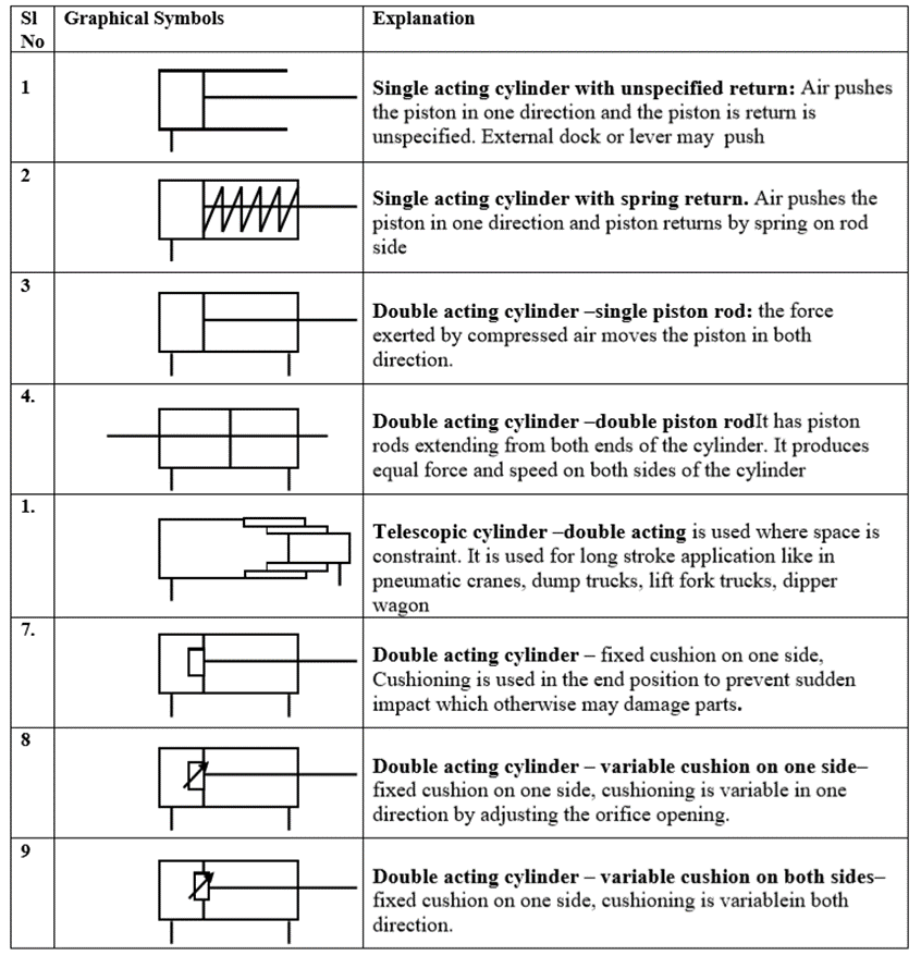
Fig. Meter-in Circuit
- Meter-out Circuit
The figure shows a meter-out circuit for flow control during the extend stroke.
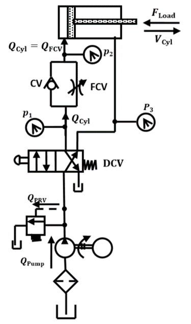
Fig. Meter-out Circuit
Both the meter-in and meter-out circuits mentioned above perform the same operation (control the speed of the extending stroke of the piston), even though the processes are exactly opposite to one another.
5.12.1 DIRECT CONTROL OF SINGLE-ACTING CYLINDER.
Pneumatic cylinders can be directly controlled by the actuation of the final directional control valve (Figure).
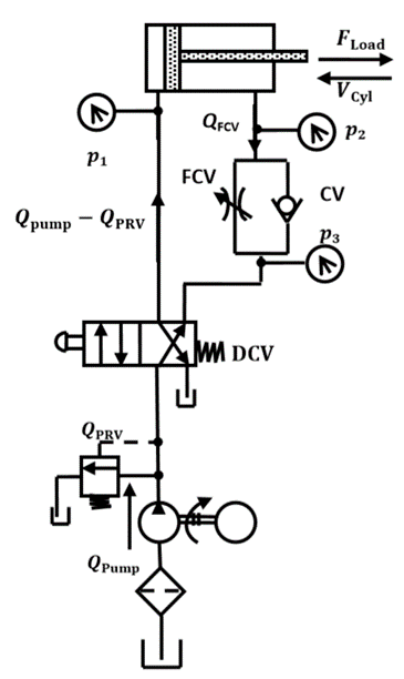
Fig. Direct Control of Single-acting Cylinder
5.12.2 INDIRECT CONTROL OF SINGLE-ACTING CYLINDER
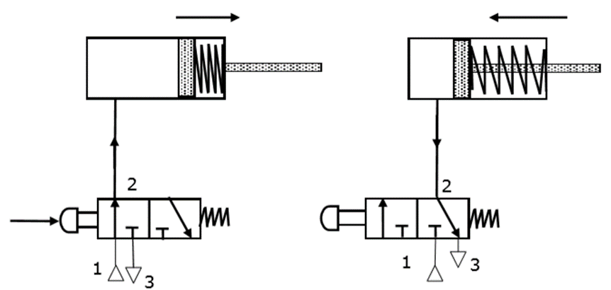
Fig. Indirect control of a single-acting cylinder
5.12.3 CONTROL OF SINGLE-ACTING CYLINDER USING “OR” VALVE
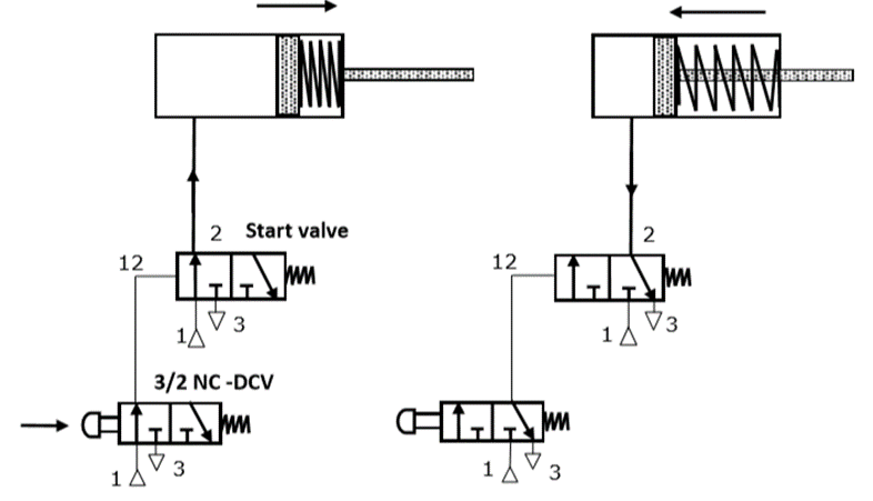
Fig. Control of a single-acting cylinder using OR valve
5.12.4 CONTROL OF SINGLE-ACTING CYLINDER USING “AND” VALVE
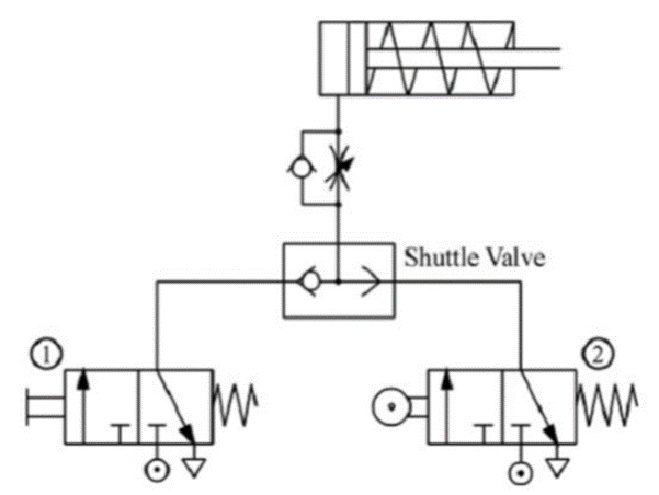
Fig. Control of a single-acting cylinder using AND valve
5.12.5 CONTROL OF SINGLE-ACTING CYLINDER USING “NOT” VALVE
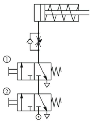
Fig. Control of a single-acting cylinder using NOT valve
5.12.6 DIRECT CONTROL OF DOUBLE-ACTING CYLINDER
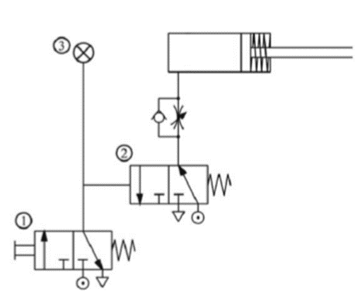
Fig. Direct control of a double-acting cylinder
5.12.7 INDIRECT CONTROL OF DOUBLE-ACTING CYLINDER USING MEMORY VALVE
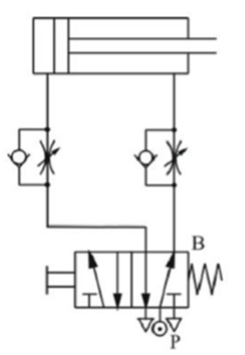
Fig. Indirect control of Double-acting cylinder using the memory valve
5.12.8 Cascading Time Delay Circuit
Pneumatic timers are used to create time delay of signals in pilot operated circuits. Available as normally closed timers and normally open timers. Usually, pneumatic timers are on-delay timers. Delay of signals is very commonly experienced in applications such as bonding of two pieces. Normally open pneumatic timers are also used in signal elimination. Normally open pneumatic timers are used as a safety device in two hand blocks
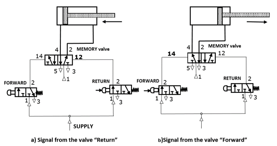
Fig. Cascading Time Delay Circuit
Industrial low-cost automation circuit makes the process simple and accurate in industries.
There are 2 types of circuit
5.14.1 Semi-Automatic Circuit
Fig shows a semi-automatic circuit used to control double-acting cylinder i.e. to control the operation carried out by the double-acting cylinder.
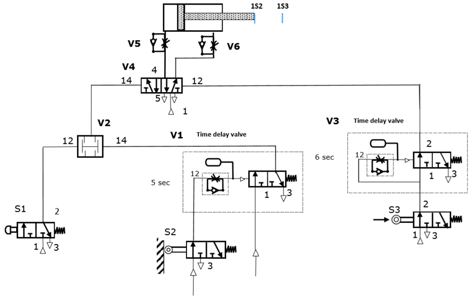
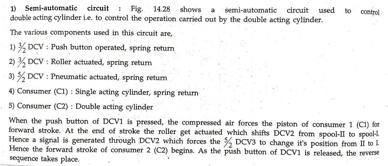
Fig. Semi-automatic circuit
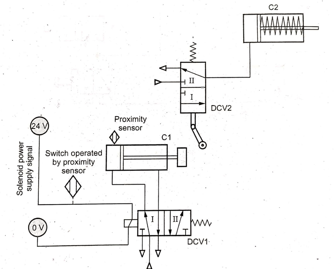
5.14.2 Fully-Automatic Circuit
The following figure shows a fully automatic circuit that controls a single-acting cylinder through the motion of the double-acting cylinder.
The control of solenoid is achieved by using a feedback signal to the PIC interface board and software.
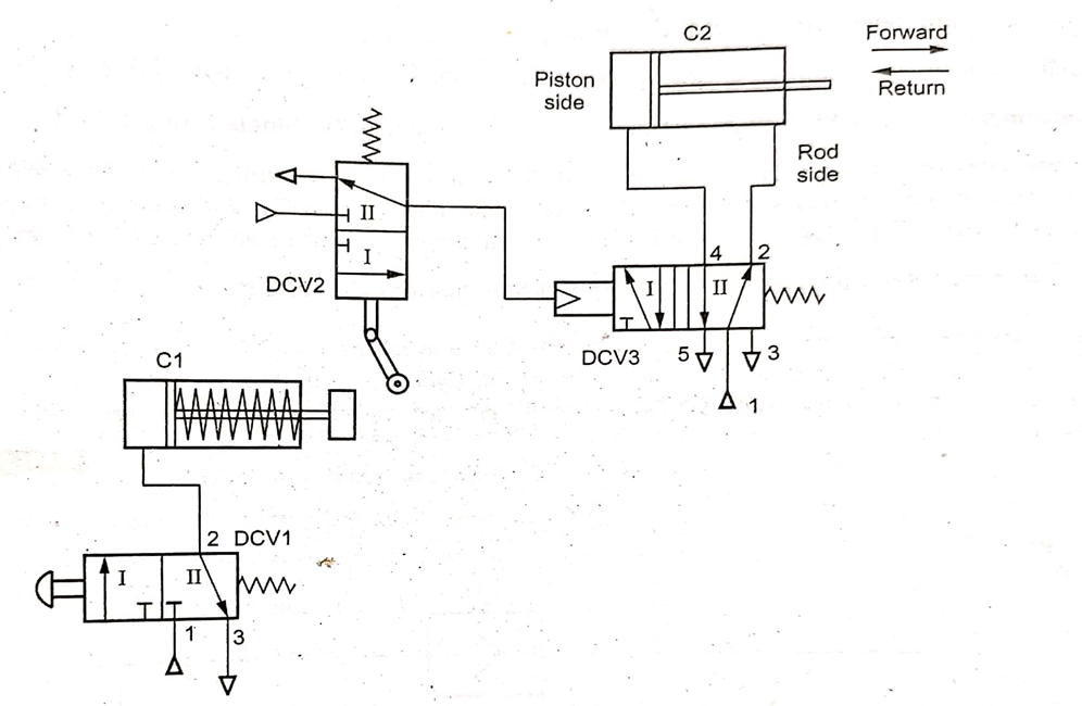
Fig. Fully-automatic circuit
References :
1. Pipenger J.J, Industrial Hydraulics, McGraw Hill
2. Pinches, Industrial Fluid Power, Prentice Hall
3. Yeaple, Fluid Power Design Handbook
4. Andrew A. Parr, Hydraulics and Pneumatics, Elsevier Science and Technology Books
5. ISO - 1219, Fluid Systems and components, Graphic Symbols
6. Standard Manufacturer’s Catalogues


