Unit 2
Data Link Layer
Data Link Layer Services
The primary function of the data link layer is to provide a well-defined service interface to the network layer above it.
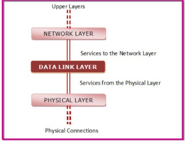
The data link layer offers three types of services.
- Unacknowledged connectionless service –
- The data link layer of the sending machine sends independent frames to the data link layer of the receiving machine.
- The receiving machine does not acknowledge receiving the frame. No logical connection is set up between the host machines. Error and data loss are not handled in this service. This is applicable in Ethernet services and voice communications.
- Acknowledged connectionless service –
- No logical connection is set up between the host machines, but each frame sent by the source machine is acknowledged by the destination machine on receiving.
- If the source does not receive the acknowledgment within a stipulated time, then it resends the frame. This is used in Wifi (IEEE 802.11) services.
- Acknowledged connection-oriented service –
This is the best service that the data link layer can offer to the network layer.
A logical connection is set up between the two machines and the data is transmitted along this logical path.
The frames are numbered which keeps track of loss of frames and ensures that frames are received in correct order.
The service has three distinct phases −
- Set up of connection – A logical path is set up between the source and the destination machines. Buffers and counters are initialised to keep track of frames.
- Sending frames – The frames are transmitted.
- Release connection – The connection is released; buffers and other resources are released.
It is appropriate for satellite communications and long-distance telephone circuits.
2.2.1 Introduction
Data-link layer uses some error control mechanism to ensure that frames that is data bit streams are transmitted with certain level of accuracy.
The errors can be controlled if we know what type of errors occur.
The types of error are:
Single bit error
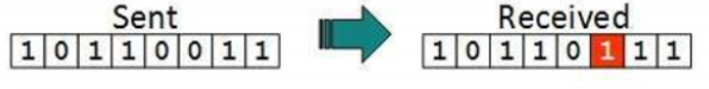
In this frame there is only one bit anywhere which is corrupt.
Multiple bits error
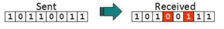
The frame is received with more than one bit in the corrupted state.
Burst Error
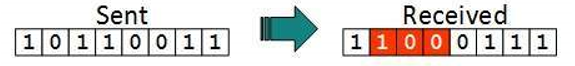
In this the frame contains more than one consecutive bit which are corrupted.
Error control mechanism is achieved by
- Error detection
- Error correction
2.2.2 Error Detection
The errors in the received frames are detected by means of Parity Check and Cyclic Redundancy Check (CRC).
In both the cases extra, few bits are sent along with actual data to confirm that bits received at other end are same as they were sent.
If the countercheck at receiver’ end fails, then the bits are considered as corrupted.
Parity Check
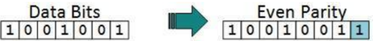
Here an extra bit is sent along with the original bits to make number of 1s either even in case of even parity, or odd in case of odd parity.
The sender while creating a frame counts the number of 1s in it.
For example, if even parity is used and number of 1s is even then one bit with value 0 is added. This way number of 1s remains even.
If the number of 1s is odd, to make it even a bit with value 1 is added.
The receiver counts the number of 1s in a frame. If the no of count of 1s is even and even parity is used, the frame is not corrupted and is accepted.
If the count of 1s is odd and odd parity is used, the frame is still not corrupted.
If a single bit flips in transit, the receiver can detect it by counting the number of 1s. But if more than one bit are erroneous, then it is hard for the receiver to detect the error.
Cyclic Redundancy Check (CRC)
CRC is a different approach to detect if the received frame contains valid data. This technique involves binary division of the data bits being sent. The divisor is generated using polynomials. The sender performs a division operation on the bits being sent and calculates the remainder. Before sending the actual bits, the sender adds the remainder at the end of the actual bits. Actual data bits plus the remainder is called a codeword. The sender transmits data bits as codewords.
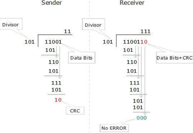
At the other end, the receiver performs division operation on codewords using the same CRC divisor. If the remainder contains all zeros the data bits are accepted, otherwise it is considered as there some data corruption occurred in transit.
Error Correction
Error correction is obtained in two ways:
- Backward Error Correction: When the receiver detects an error in the received data , it requests back the sender to retransmit the data unit.
- Forward Error Correction: When the receiver detects some error in the data received, it executes error-correcting code which helps it to auto-recover and to correct some kinds of errors.
To correct the error in data frame, the receiver must know exactly which bit in the frame is corrupted. To locate the bit in error, redundant bits are used as parity bits for error detection.
For example, we take ASCII words (7 bits data), then there could be 8 kind of information we need:
First seven bits to tell us which bit is error and one more bit to tell that there is no error.
For m data bits, r redundant bits are used. r bits can provide 2r combinations of information. In m+r bit codeword, there is possibility that the r bits themselves may get corrupted. So, the number of r bits used must inform about m+r bit locations plus no-error information, i.e. m+r+1.
2 r > = m+r+1
Hamming code
The hamming code technique is an error-detection and error-correction technique was proposed by R.W. Hamming.
Whenever a data packet is transmitted over the network there are possibilities that the data bits may get lost or damaged during transmission.
For example
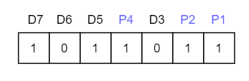
Let us say you have received a 7-bit Hamming code which is 1011011.
Consider the redundant bits.
The redundant bits are some extra binary bits that are not part of the original data but generated & added to the original data bit.
This is done to ensure that the data bits do not get damaged and if they do we can recover them.
Now the question arises, how do we determine the number of redundant bits to be added?
Using the formula, 2r >= m+r+1; where r = redundant bit & m = data bit.
From the formula there are 4 data bits and 3 redundancy bits, referring to the received 7-bit hamming code.
What is Parity Bit?
To know about parity bit, which is a bit appended to the data bits which ensures that the total number of 1's are even (even parity) or odd (odd parity).
While checking the parity, if the total number of 1's are odd then write the value of parity bit P1(or P2 etc.) as 1 (which means the error is there ) and if it is even then the value of parity bit is 0 (which means no error).
Hamming Code: Error Detection
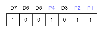
The first step is to identify the bit position of the data & all the bit positions which are powers of 2 are marked as parity bits (e.g. 1, 2, 4, 8, etc.). The following image will help in visualizing the received hamming code of 7 bits.
First, we need to detect whether there are any errors in this received hamming code.
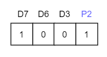
Step 1:
For checking parity bit P1, use check one and skip one method, which means,
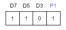
Here we observe the total number of bits are odd so hence the value of parity bit as P1 = 1. This means error is there.
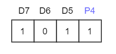
Step 2:
Check for P2 but while checking for P2, we will use check two and skip two method, which will give us the following data bits. But remember since we are checking for P2, so we must start our count from P2, here P1 should not be considered.
As we can observe that the number of 1's are even, then we will write the value of P2 = 0. This means there is no error.
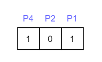
Step 3:
Check for P4 but while checking for P4, we will use check four and skip four method, which will give us the following data bits. But remember since we are checking for P4, so we have started our count from P4(P1 & P2 should not be considered).
As we can observe that the number of 1's are odd, then we will write the value of P4 = 1. This means the error is there.
So, from the above parity analysis, P1 & P4 are not equal to 0, so we can clearly say that the received hamming code has errors.
Hamming Code: Error Correction
Since we found that received code has an error, now we must correct them.
To correct the errors, use the following steps:
Now the error word E will be:
To determine the decimal value of this error word 101 which is 5 (22 *1 + 21 * 0 + 20 *1 = 5).
We get E = 5, which states that the error is in the fifth data bit. To correct it, just invert the fifth data bit.
The correct data will be:
Hamming distance
Hamming distance is a metric for comparing two binary data strings. While comparing two binary strings of equal length, Hamming distance is the number of bit positions in which the two bits are different.
The Hamming distance between two strings, a and b is denoted as d(a,b).
It is used for error detection or error correction when data is transmitted over computer networks. It is also using in coding theory for comparing equal length data words.
Calculation of Hamming Distance
In order to calculate the Hamming distance between two strings, we perform their XOR operation, (a⊕ b), and then count the total number of 1s in the resultant string.
Example
Suppose there are two strings 1101 1001 and 1001 1101.
11011001 ⊕ 10011101 = 01000100. Since, this contains two 1s, the Hamming distance, d(11011001, 10011101) = 2.
Minimum Hamming Distance
In a set of strings of equal lengths, the minimum Hamming distance is the smallest Hamming distance between all possible pairs of strings in that set.
Example
Suppose there are four strings 010, 011, 101 and 111.
010 ⊕ 011 = 001, d(010, 011) = 1.
010 ⊕ 101 = 111, d(010, 101) = 3.
010 ⊕ 111 = 101, d(010, 111) = 2.
011 ⊕ 101 = 110, d(011, 101) = 2.
011 ⊕ 111 = 100, d(011, 111) = 1.
101 ⊕ 111 = 010, d(011, 111) = 1.
Hence, the Minimum Hamming Distance, dmin = 1.
Parity check code
A simple parity check code is a single bit error detecting code in which n=k+1 with dmin = 2.
Even parity ensures that codeword has even no’s of 1’s and an odd parity ensures that there are odd number of 1’s in the codeword.
Simple parity check code C(5,4)
Data words | Codewords | Datawords | Codewords |
0000 | 00000 | 1000 | 10001 |
0001 | 00011 | 1001 | 10010 |
0010 | 00101 | 1010 | 10100 |
0011 | 00110 | 1011 | 10111 |
0100 | 01001 | 1100 | 11000 |
0101 | 01010 | 1101 | 11011 |
0110 | 01100 | 1110 | 11101 |
0111 | 01111 | 1111 | 11110 |
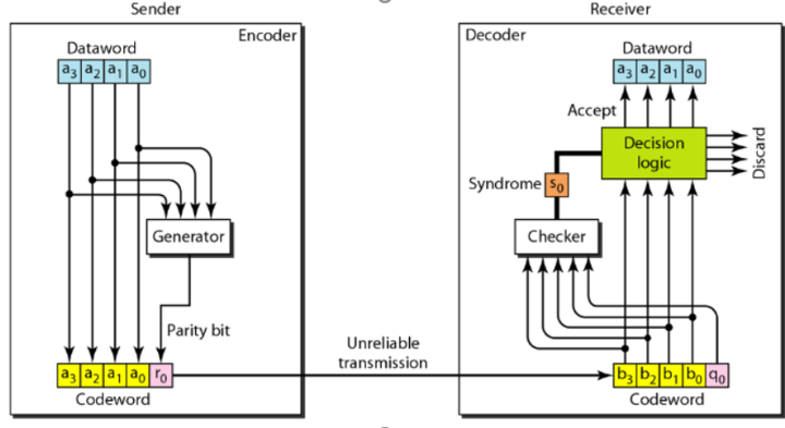
Let us look at some transmission scenarios. Assume the sender sends the data word 1011. The codeword created from this data word is 10111, which is sent to the receiver.
Here we examine five cases:
1. No error occurs; the received codeword is 10111. The syndrome is 0. The data word 1011 is created.
2. One single-bit error changes a1 . The received codeword is 10011. The syndrome is 1. No data word is created.
3. One single-bit error changes r0 . The received codeword is 10110. The syndrome is 1. No data word is created.
4.An error changes r0 and a second error changes a3 .The received codeword is 00110. The syndrome is 0. The dataword 0011 is created at the receiver. Note that here the dataword is wrongly created due to the syndrome value.
5. Three bits—a3, a2, and a1—are changed by errors.The received codeword is 01011. The syndrome is 1. The dataword is not created. This shows that the simple
parity check is guaranteed to detect one single error, can also find any odd number of errors.
CRC Polynomials
Cyclic Redundancy Check is an error detection method based on binary division.
The CRC generator is an algebraic polynomial represented in bit pattern. The bit pattern obtained from the CRC generator uses the following rules which states that the power of each term gives the position of the bit and the coefficient gives the value of the bit.
For example:
Consider the CRC generator x7 + x6 + x4 + x3 + x + 1
The corresponding pattern is obtained
1x7 +1 x6 +0 x 5 +1 x 4 +1 x3 +0 x2 + 1 x1 +1 x0
Thus, we get
1 1 0 1 1 0 1 1
For the given CRC generator the corresponding binary pattern is 11011011
Properties Of CRC Generator-
The algebraic polynomial chosen as a CRC generator should have at least the following properties-
Rule-01:
- It should not be divisible by x.
- This condition guarantees that all the burst errors of length equal to the length of polynomial are detected.
Rule-02:
It should be divisible by x+1.
- This condition guarantees that all the burst errors affecting an odd number of bits are detected.
Note :
If the CRC generator is chosen according to the above rules, then-
- CRC can detect all single-bit errors
- CRC can detect all double-bit errors provided the divisor contains at least three logic 1’s.
- CRC can detect any odd number of errors provided the divisor is a factor of x+1.
- CRC can detect all burst error of length less than the degree of the polynomial.
- CRC can detect most of the larger burst errors with a high probability.
Error detection using CRC technique involves the following steps-
Step-01: Calculation Of CRC At Sender Side-
At sender side,
- A string of n 0’s is appended to the data unit to be transmitted.
- Here, n is one less than the number of bits in CRC generator.
- Binary division is performed of the resultant string with the CRC generator.
- After division, the remainder so obtained is called as CRC.
- It may be noted that CRC also consists of n bits.
Step-02: Appending CRC To Data Unit-
At sender side,
- The CRC is obtained after the binary division.
- The string of n 0’s appended to the data unit earlier is replaced by the CRC remainder.
Step-03: Transmission To Receiver-
- The newly formed code word (Original data + CRC) is transmitted to the receiver.
Step-04: Checking at Receiver Side-
At receiver side,
- The transmitted code word is received.
- The received code word is divided with the same CRC generator.
- On division, the remainder so obtained is checked.
The following two cases are possible-
Case-01: Remainder = 0
If the remainder is zero,
- Receiver assumes that no error occurred in the data during the transmission.
- Receiver accepts the data.
Case-02: Remainder ≠ 0
If the remainder is non-zero,
- Receiver assumes that some error occurred in the data during the transmission.
- Receiver rejects the data and asks the sender for retransmission.
A bit stream 1101011011 is transmitted using the standard CRC method. The generator polynomial is x4+x+1. What is the actual bit string transmitted?
Solution-
- The generator polynomial G(x) = x4 + x + 1 is encoded as 10011.
- Clearly, the generator polynomial consists of 5 bits.
- So, a string of 4 zeroes is appended to the bit stream to be transmitted.
- The resulting bit stream is 11010110110000.
Now, the binary division is performed as-
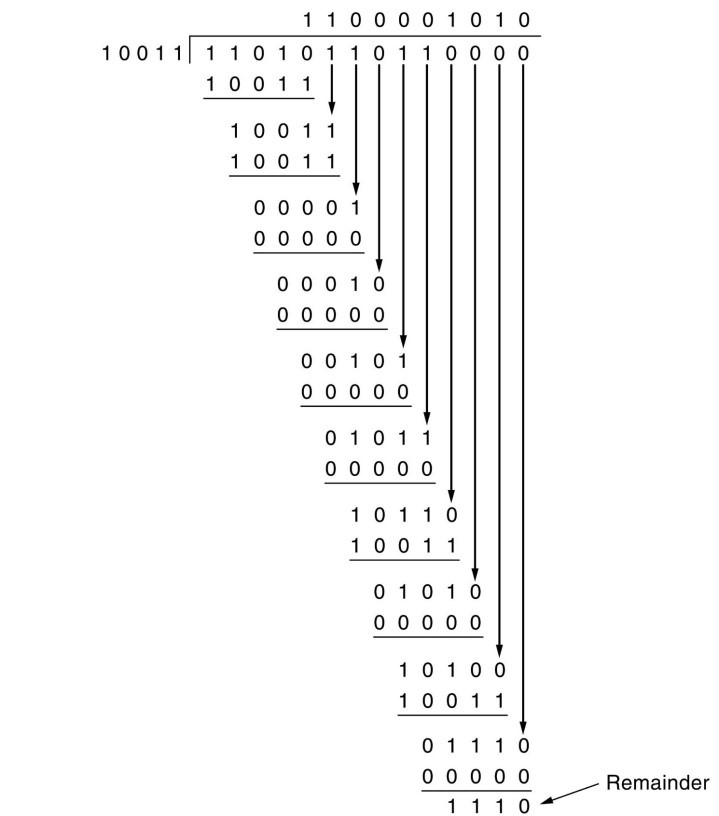
From here, CRC = 1110.
Now,
- The code word to be transmitted is obtained by replacing the last 4 zeroes of 11010110110000 with the CRC.
- Thus, the code word transmitted to the receiver = 11010110111110.
Advantages of Cyclic Code:
The advantage of cyclic codes over most of the other codes are as under :
(i) Easy to encode.
(ii) Possess a well- defined mathematical structure which has led to development of very efficient decoding schemes for them.
(iii) Methods that are to be used for error detection and correction are simpler and easy to implement.
(iv) Methods do not need look-up table decoding.
(v) Possible to detect the error bursts using the cyclic codes.
Other cyclic codes
One’s Complement
Checksum of a block of data is the complement of the one's complement of the 16-bit sum of the block.
If checksum is included in the block of data, the new block of data will have its checksum zero.
This is how checksum is used for error detection in datagram transmissions.
For example, consider a block of data:
0x23fb 0x34c0 0xa090 0xbcaf 0xfc05
The Sum is 0x2b1ff.
To calculate 16-bit 1's complement sum, excess digit 2 needs to be added back to the least significant 16 bits:
0xb1ff+ 2 ---------- 0xb201
The complement of this is 0x4dfe. This is the checksum of the block of data.
Note that checksum (checksum + data)=0.
So, if we transmit the block of data including the checksum field, the receiver should see a checksum of 0 if there are no bit errors.
Internet Checksum
Internet Protocols (IP,TCP,UDP) use check bits to detect errors instead of using CRC polynomial.
Checksum must be recalculated at every router , the algorithm for checksum was selected for its ease of implementation instead of strength of error detection capability.
Algorithm:
Let IP header consists of L 16-bit words bo,b1,b2……,bL-1.
The algorithm appends 16-bit checksum bL to the header . The checksum bL is calculated as follows.
Treating each 16-bit word as an integer find
x = (bo + b1 + b2 + …………+ bL-1) modulo 2 16 -1
The checksum is given by bL = -x
Thus, the headers must satisfy the following pattern
0 = (bo + b1 + b2 + …………+ bL-1) modulo 2 16 -1
Example
Assume 4- bit words use mod 2 4 – 1 arithmetic
Bo = 1100
b1 = 1010
Use Modulo Arithmetic
Use Binary Arithmetic
Modulo Arithmetic
Use mod 2 4 – 1 arithmetic
Bo = 1100=12
b1 = 1010 = 10
Bo + b1 = 12 + 10 = 7 mod 5
b2 = -7 = 8 md 15
Therefore
b2 = 1000
Use Binary Arithmetic
10000 mod 15 = 0001
Bo + b1 = 1100 + 1010 = 10110
10000 + 0110
0001+0110
=0111=7
Take 1’s complement b2 = -0111= 1000
- Framing is a point-to-point connection between two computers or devices which consists of a wire in which data is transmitted as a stream of bits.
- However, these bits must be framed into discernible blocks of information.
- Framing is the function of the data link layer. It provides a way for a sender to transmit a set of bits that are meaningful to the receiver.
- Ethernet, token ring, frame relay, and other data link layer technologies have their own frame structures.
- Frames have headers that contain information such as error-checking codes.
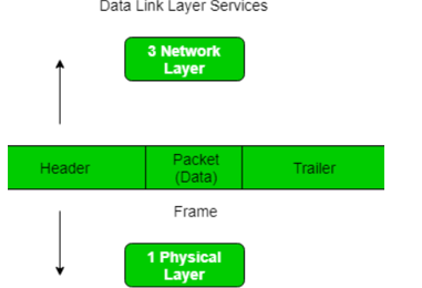
At data link layer it extracts message from sender and provide it to the receiver by providing sender’s and receiver’s address.
The advantage of using frames is that data is broken up into recoverable chunks that can easily be checked for corruption.
Types of framing – There are two types of framing:
1. Fixed size – The frame is of fixed size and there is no need to provide boundaries to the frame, length of the frame itself acts as delimiter.
2. Variable size – In this there is need to define end of frame as well as beginning of next frame to distinguish.
This can be done in two ways:
- Length field – We can introduce a length field in the frame to indicate the length of the frame. Used in Ethernet(802.3).
- End Delimeter (ED) – We can introduce an ED(pattern) to indicate the end of the frame. Used in Token Ring.
Flow control in computer networks is defined as the process of managing the rate of data transmission between two systems(nodes), this mechanism ensures that the rate of data (transmitted by the sender) is within the receiving capacity of the receiver node.
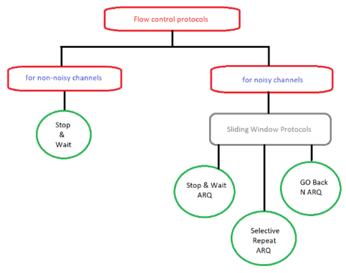
Flow control Protocol
From the figure there are two protocols, Stop & Wait and a sliding window.
In stop & wait the sender node sends one frame and then waits for the feedback from the receiver node.
On the other hand, in the sliding window protocol, the sender node keeps on sending frames to the receiver node without waiting for any feedback and it re-sends the frame which is/are damaged or suspected.
The efficiency of stop &wait protocol is less, while the efficiency of the sliding window protocol is more than stop & wait protocol.
The stop & wait protocol is half-duplex whereas sliding window protocol is full duplex.
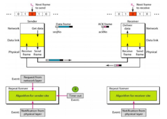
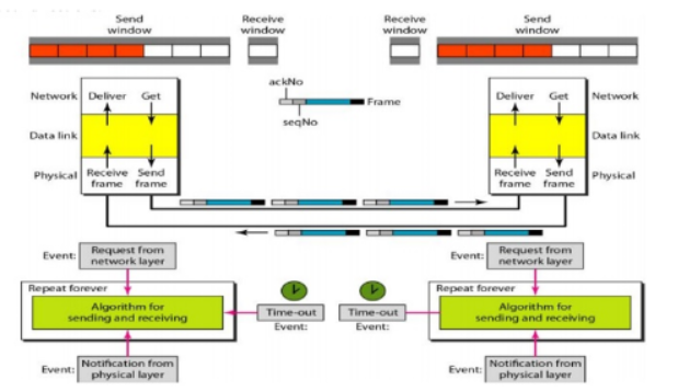
Simplest Protocol
It is a unidirectional protocol in which data frames are traveling in one direction-from the sender to receiver. It has no flow or error control .The data link layer of the receiver immediately removes the header from the frame and hands the data packet to its network layer, which can also accept the packet immediately.
Design
The sender site cannot send a frame until its network layer has a data packet to send. The receiver site cannot deliver a data packet to its network layer until a frame arrives.
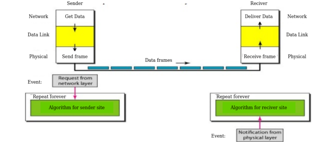
The design of the simplest protocol with no flow or error control
If the protocol is implemented as a procedure, we need to introduce the idea of events in the protocol. The procedure at the sender site is constantly running; there is no action until there is a request from the network layer. The procedure at the receiver site is also constantly running, but there is no action until notification from the physical layer arrives.
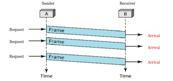
For example
The sender sends a sequence of frames without even thinking about the receiver. To send three frames, three events occur at the sender site and three events at the receiver site. Note that the data frames are shown by tilted boxes; the height of the box defines the transmission time difference between the first bit and the last bit in the frame.
Stop-and-Wait Protocol
If data frames arrive at the receiver site faster than they can be processed, the frames must be stored until their use.
In Stop-and-Wait Protocol the sender sends one frame, stops until it receives confirmation from the receiver (okay to go ahead), and then sends the next frame.
Design
The Figure illustrates the mechanism.
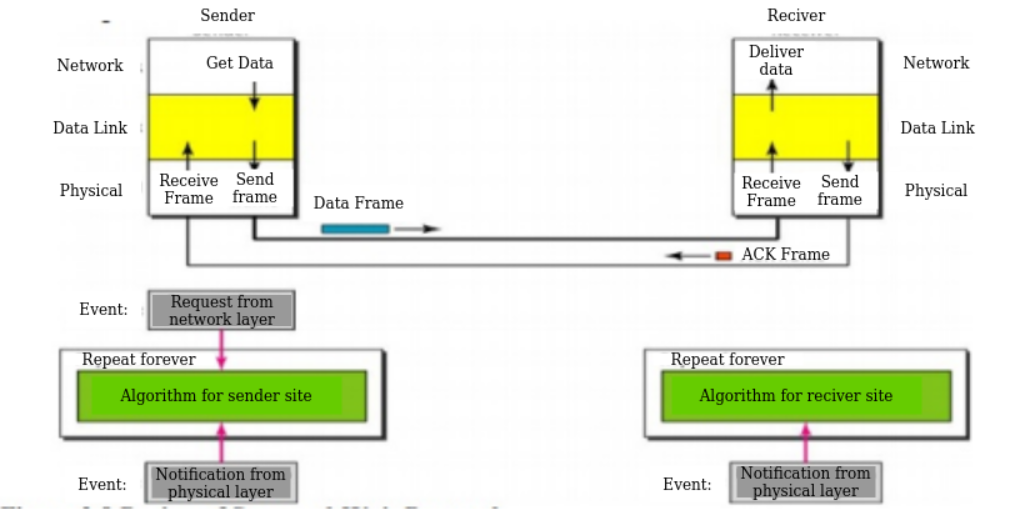
At any time, there is either one data frame on the forward channel or one ACK frame on the reverse channel. We therefore need a half-duplex link.
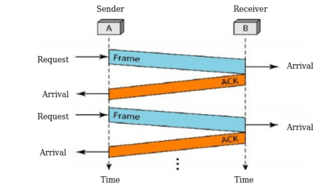
Figure shows an example of communication using this protocol. The sender sends one frame and waits for feedback from the receiver. When the ACK arrives, the sender sends the next frame. Note that sending two frames in the protocol involves the sender in four events and the receiver in two events.
Stop and Wait Automatic Request
The Stop-and-Wait Automatic Repeat Request (Stop-and-Wait ARQ) adds a simple error control mechanism to the Stop-and-Wait Protocol.
For detect and correct corrupted frames, we add redundancy bits to the data frame. When the frame arrives at the receiver site, it is checked and if it is corrupted, it is silently discarded. The detection of errors in this protocol is manifested by the silence of the receiver.
Sequence Numbers
The protocol specifies the frames which need to be numbered. This is done by using sequence numbers. A field is added to the data frame to hold the sequence number of that frame. For example, if we decide that the field is m bits long, the sequence numbers start from 0, go to 2m - 1, and then are repeated.
Acknowledgment Numbers
The acknowledgment numbers always announce the sequence number of the next frame expected by the receiver.
For example, if frame 0 has arrived safe and sound, the receiver sends an ACK frame with acknowledgment 1 (meaning frame 1 is expected next). If frame 1 has arrived safe and sound, the receiver sends an ACK frame with acknowledgment 0 (meaning frame 0 is expected).
Go-Back-N Automatic Repeat Request
In this protocol we send several frames before receiving acknowledgments a copy of these frames is kept until the acknowledgments arrive.
Sequence Numbers
Frames from the sending station are numbered sequentially. However, because we need to include the sequence number of each frame in the header, we need to set a limit. If the header of the frame allows m bits for the sequence number, the sequence numbers range from 0 to 2m - 1.
Sliding Window
The sliding window is an abstract concept that defines the range of sequence numbers that is the concern of the sender and receiver.
The sender and receiver need to deal with only part of the possible sequence numbers. The range which is the concern of the sender is called the send sliding window; the range that is the concern of the receiver is called the receive sliding window.
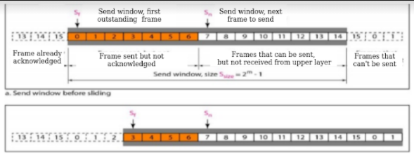
The sender does not worry about these frames and keeps no copies of them. The second region, colored in Figure which defines the range of sequence numbers belonging to the frames that are sent and have an unknown status.
The window itself is an abstraction in which three variables define its size and location at any time.
These variables Sf(send window, the first outstanding frame), Sn (send window, the next frame to be sent), and Ssize (send window, size).
The variable Sf defines the sequence number of the first (oldest) outstanding frame. The variable Sn holds the sequence number that will be assigned to the next frame to be sent. Finally, the variable Ssize defines the size of the window, which is fixed in our protocol.
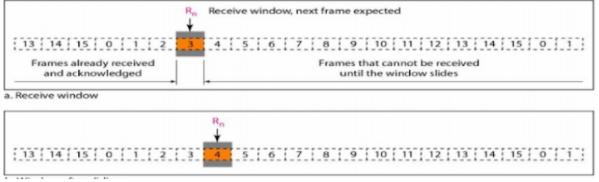
The receive window makes sure that the correct data frames are received and that the correct acknowledgments are sent. The size of the receive window is always 1.
Selective Repeat Automatic Repeat Request
Go-Back-N ARQ simplifies the process at the receiver site. The receiver keeps track of only one variable, and there is no need to buffer out-of-order frames they are discarded.
However, this protocol is very inefficient for a noisy link. In a noisy link a frame has higher probability of damage, which means the resending of multiple frames. This resending uses up the bandwidth and slows down the transmission.
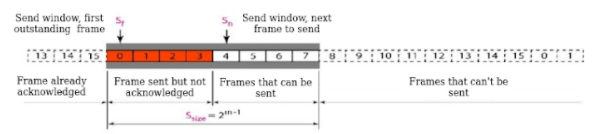
Windows
The Selective Repeat Protocol also uses two windows: a send window and a receive window.
First, the size of the send window is much smaller it is 2m- 1.
Second, the receive window is the same size as the send window.
The send window maximum size can be 2m- 1.
For example, if m = 4, the sequence numbers go from 0 to 15, but the size of the window is just 8 .The smaller window size means less efficiency in filling the pipe, but the fact that there are fewer duplicate frames can compensate for this.
The receive window in Selective Repeat is different from the one in Go Back- N. First, the size of the receive window is the same as the size of the send window (2m- 1). The figure shows the receive window in this protocol. Those slots inside the window that are coloured define frames that have arrived out of order and are waiting for their neighbours to arrive before delivery to the network layer.
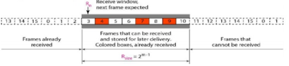
Receive window for Selective Repeat ARQ
Piggybacking
The three protocols in this section are all unidirectional: data frames flow in only one direction although control information such as ACK and NAK frames can travel in the other direction.
In real life, data frames are normally flowing in both directions: from node A to node B and from node B to node A. This means that the control information also needs to flow in both directions.
A technique called piggybacking is used to improve the efficiency of the bidirectional protocols. When a frame is carrying data from A to B, it can also carry control information about arrived (or lost) frames from B; when a frame is carrying data from B to A, it can also carry control information about the arrived (or lost) frames from A.
Draw PPPoE connection diagram with multiple devices, FFTH connection diagram,
Point-to-Point Protocol over Ethernet (PPPoE) combines PPP, with the Ethernet link-layer protocol which allows users to connect to a network of hosts over a bridge or access concentrator.
Understanding Point-to-Point Protocol over Ethernet
Point-to-Point Protocol over Ethernet (PPPoE) combines PPP, which typically runs over broadband connections, with the Ethernet link-layer protocol that allows users to connect to a network of hosts over a bridge or access concentrator. PPPoE enables service providers to maintain access control through PPP connections and also manage multiple hosts at a remote site.
PPPoE connects multiple hosts on an Ethernet LAN to a remote site through a single customer premises equipment (CPE) device—a Juniper Networks device. Hosts share a common digital subscriber line (DSL), a cable modem, or a wireless connection to the Internet.
How to setup multiple PPPoE connections
1) Install multiple network devices (ethernet cards).
(you can probably do this with one and use eth0:0, eth0:1, etcetera but, it's a bad idea).
2) Make note of each device's MAC address.
3) Make sure the correct interface is assigned to the correct network card.
Edit /etc/udev/rules.d/70-persistent-net.rules file so that the MAC address of each card matches the interface you want. You must do this so the correct pppoe connection connects to the correct modem.
4) Run pppoe-setup and set up the connection for connection #1.
5) mv /etc/ppp/pppoe.conf /etc/pppoe-connection1.conf
6) Run pppoe-setup and set up the connection for connection #2.
7) mv /etc/ppp/pppoe.conf /etc/pppoe-connection2.conf
8) Repeat steps 6 & 7 for each of the remaining DSL connections.
-setup is complete-
How to start the connections
1) Run pppoe-start /etc/ppp/pppoe-connection1.conf
2) Run pppoe-start /etc/ppp/pppoe-connection2.conf
3) Repeat step 2 for all remaining connections.
At this point, you should have ppp0, ppp1 and etc. ppp connections. Your routing table may be trashed at this point, you can clear it and use one as the default route by:
Route del default
Route add default gw ip_address_of_one_of_your_pppoe_connections
FFTH connection
Fiber to the Home or simply FTTH is a technology that uses optical fiber directly from the central point to the residential premises.It provides uninterrupted high-speed internet service. “H” includes both home and small business.
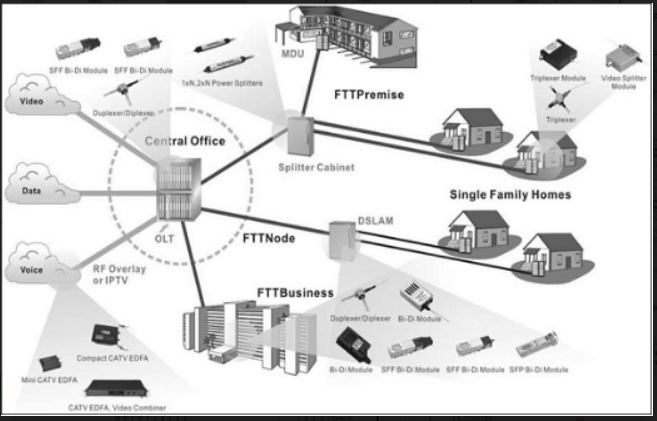
FTTH is the ultimate fiber access solution where each subscriber is connected to an optical fiber. The deployment options are based on a complete optical fiber path from the Optical Line Termination (OLT) right to the subscriber premises.
This choice facilitates high bandwidth services and content to each customer and ensures maximum bandwidth for future demands of new services.
As an access to the home over fiber, Fiber to The Home (FTTH) scenario is mainly for the single family unit (SFU), providing a comparatively small number of ports, including the following types — POTS, 10/100/1000 BASE-T, and RF (18dBmV).
Optical Fiber Method can be deployed in two ways: Active Method and Passive Method. The current mass FTTH deployment is based on the passive method.
Passive Method − The two typical technologies used in this method are Ethernet Passive Optical Network (EPON) & Gigabit-capable Passive Optical Networks (GPON
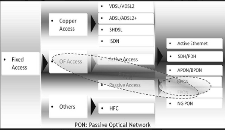
- High bit rate digital subscriber loop (VDSL) supports a maximum bit rate of 55 bps. VDSL2 has better QoS and better SNR.
- ADSL (asymmetric digital subscriber line) supports a maximum bit rate of 8Mbps, however ADSL2 can go up to 12Mbps.
- SHDSL stands for symmetric high bit rate digital subscriber line. The larger the diameter of the telephone, the longer the distance it could reach. The transmission rate depends on the diameter of the telephone wire.
- Integrated service digital network (ISDN) is based on circuit-switched network.
References:
Tcp/Ip Protocol Suite Book by Behrouz A. Forouzan
Open Systems Networking: TCP/IP and OSI Book by David M. Piscitello and Lyman Chapin
Patterns in Network Architecture: A Return to Fundamentals Book by John Day


