Unit - 2
Voltage regulation of three phase synchronous generator
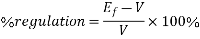
The voltage regulation of a synchronous generator is the rise in voltage at the terminals when the load is reduced from full load rated value to zero, speed and field current remaining constant.
It can be written as
Per unit voltage regulation
Percent voltage regulation
Where  =magnitude of generated voltage per phase
|V|= magnitude of rated terminal voltage per phase
The voltage regulation depends upon the power factor of the load. For unity and lagging power factor, there is always a voltage drop with the increase of loads but for a certain leading power, the full load voltage regulation is zero. In this case, the terminal voltage is the same for both full load and no-load conditions. At lower leading power factor, the voltage rises with the increase of load and the regulation is negative.
Key takeaway
Percent voltage regulation
Determination of voltage regulation
a) Direct load test-
The alternator is run at synchronous speed and its terminal voltage is adjusted to its rated value V. The load is varied until the ammeter and wattmeter indicate rated values at the given power factor. Then the load is removed and the speed and field excitation are kept constant. The open circuit or no load voltage  is recorded. The voltage regulation is found from
Percentage voltage regulation
The method of direct loading is suitable only for small alternators of power rating less than 5kVA.
b) Indirect methods
Synchronous impedance method or EMF method this method is based on the concept of replacing the effect of armature reaction by a fictitious reactance.
For a synchronous generator

Where:

Following test are performed on an alternator to know its performance
DC resistance test
Assume that the alternator is star connected with DC field winding open, measure the DC resistance between each pair of terminals either by using ammeter voltmeter method or by using Wheatstone bridge. The average of three sets of resistance values of  is taken. This value of is divided by 2 to obtained the DC resistance per phase.
Since the effective AC resistance is larger than DC resistance due to skin effect, therefore, the effective AC resistance per phase is obtained by multiplying the DC resistance by a factor 1.20 to 1.75 depending on the size of the machine.
A typical value to use in the calculation would be 1.25.
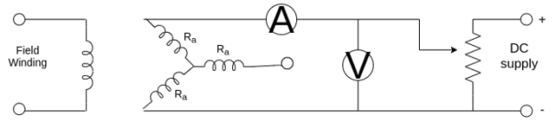
Fig 1 DC Resistance Test
Open circuit test
The alternator is run at rated synchronous speed and the load terminals are kept open. That is, all the loads are disconnected. The field current is set to zero.
Then the field current is gradually increased in steps, and the terminal voltage  is measured at each step. The excitation current may be increased to get 25% more than rated voltage of the alternator.
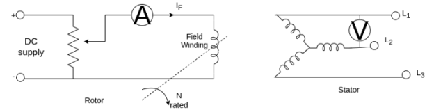
Fig 2 Open Circuit Test
A graph is plotted between the open-circuit phase voltage  and field current
 .
.
The characteristic curves so obtained are called open circuit characteristics. The linear portion of an open circuit characteristics is called the air gap line characteristic.
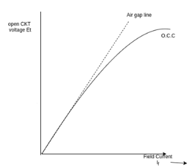
Fig 3 Open circuit characteristics
Short circuit test-
The armature terminals are shorted through ammeters. Care should be taken in performing this test, and the field current should first be decreased to zero before starting the alternator. Each ammeter should have range greater than the rated full load value.
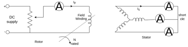
Fig 4 Short Circuit Test
The alternator is then run at synchronous speed. Then the field current is gradually increased in steps, and the armature current is measured at each step. The field current may be increased to get armature currents up to 150% of the rated value. The field current  and the average of three ammeter readings at each step is taken. A graph is plotted between the armature current
  and the field current
  The characteristic so obtained is called short circuit characteristic. The characteristic is a straight line.
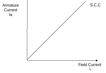
Fig 5 Short Circuit Characteristics
Calculation of 
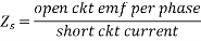
The open circuit characteristics and short circuit characteristic are drawn on the same sheet. Determine the value of  at the field current that gives the rated alternator voltage per phase. The synchronous impedance
  will then be equal to the open circuit voltage divided by the short circuit current at the that field current which gives the rated EMF per phase.
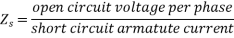
For the same value of field current.
The synchronous reactance is found as follows

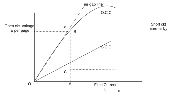
Fig 6 Open circuit characteristics and short circuit characteristic are drawn on the same sheet.
Consider the field current OA that produces rated alternator voltage per phase, corresponding to this field current the open circuit voltage is AB
Assumptions in the synchronous impedance method
1) The synchronous impedance is constant. At all times, the synchronous impedance is the ratio of the open circuit voltage to the short circuit current. When o.c.c. And s.c.c. Are linear, synchronous impedance  is constant. Above the knee of o.c.c. When the saturation starts, the synchronous impedance decreases. This is due to the fact that the o.c.c. And s.c.c. Approach each other. In this test we do not consider the effect of saturation and the value of synchronous impedance changes.
2) The flux under test conditions is the same as that under load conditions. It is assumed that a given value of field current always produces the same flux. This assumption introduces considerable error. When the armature is short circuited, the current in the armature lags the generated voltage by almost 90°, and hence armature reaction is almost completely demagnetizing. The actual resultant flux, and hence generated voltage is very small.
3) The effect of the armature reaction flux can be replaced by a voltage drop proportional to the armature current and that the armature reaction voltage drop is added to the armature reactance voltage drop.
The shift of armature flux varies with the power factor and the load current, and a distortion of the main field flux is produced. Thus, the armature reaction voltage is not in phase with the reactance voltage drop.
4) The magnetic reluctance to the armature flux is constant regardless of the power factor.
Regulation obtained by using synchronous impedance method is higher than that obtained by actual loading. Hence this method is called the pessimistic method.
Key takeaway
When o.c.c. And s.c.c. Are linear, synchronous impedance  is constant. Above the knee of o.c.c. When the saturation starts, the synchronous impedance decreases. This is due to the fact that the o.c.c. And s.c.c. Approach each other. In this test we do not consider the effect of saturation and the value of synchronous impedance changes.
Examples
1) 500 volt ,50KVA single phase alternator has an effective armature resistance of 0.2 ohm. An excitation current of 10A produce 200A, armature current on short circuit and emf of 450V and open circuit. Calculate the synchronous reactance.
Solution: - 
=2.25ohm


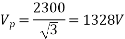
2) 3 phase, 1500 kVA, star-connected, 50 Hertz, 2300 V alternator has a resistance between each pair of terminals as measured by direct current is 0.16 ohm. Assume that the effective resistance is 1.5 times the ohmic resistance. A field current of 70 A produces a short-circuit current equal to full load current of 376 A in each line. The same field current produces an EMF of 700V on open circuit. Determine the synchronous reactance of the machine and its full load regulation at 0.8 power factor lagging.
Solution: - At lagging power factor

Percentage regulation
Ohmic resistance per phase 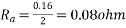
Effective resistance per phase
=0.12ohm
For same 70-amp field current

=1.075ohm
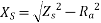
=1.068ohm


As a star connected alternator
 lagging


=1631V
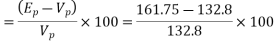
Percentage voltage regulation=
=22.8%
3) A 3-phase star connected alternator is rated at 1600 kVA, 1350 V, the armature effective resistance and synchronous reactance are 1.5 ohm and 30 ohm respectively per phase. Calculate the percentage regulation for a load of 1280 kW at power factors of
a) 0.8 leading
b) Unity
c) 0.8 lagging
a) 


For leading PF


Voltage regulation=
= -11.99%
b) Unity PF


Voltage regulation=
=3.227%
c) Power factor 0.8 lagging.
Magnitude of  will be the same as calculated in first case


Voltage regulation=
=18.6 %
4. A 3 phase star connected round rotor synchronous generator rated at 10KVA 230V has an armature resistance of 0.5Ω per phase and a synchronous reactance of 1.2 Ω per phase. Calculate the percent voltage regulation at full load at power factors of
a) 0.8 lagging
b) 0.8 leading
c) Determine the power factor such that the voltage regulation is zero on full load

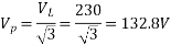
Let  be taken as reference phasor


a) Power factor 0.8 lagging


Voltage regulation
=21.8%
b) Power factor 0.8 leading


Voltage regulation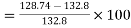
=-3.06%
c) Let  be the required power factor


Voltage regulation=
For zero voltage regulation.


5. A three, 10KVA, 400V,50Hz star connected alternator supplies the rated load at 0.8 power factor lagging. If the armature resistance is 0.5Ω and synchronous reactance is 10 Ω, find the torque angle and voltage regulation.

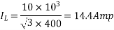

Let  be taken as reference phasor
Voltage regulation=
=47.89%
Magnetomotive force method
This method is also known as ampere- turn method. The mmf method replaces the effect of armature leakage reactance by an equivalent additional armature reaction MMF, so that this MMF may be combined with the armature reaction MMF. The following information is required to predict the regulation by the MMF method.
1) The resistance of the stator winding per phase.
2) Open circuit characteristic at synchronous speed.
3) Short circuit characteristic.
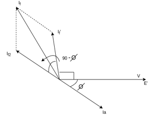
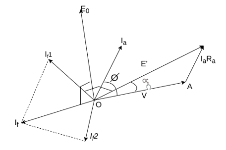
The following procedure is used for drawing the phasor diagram at lagging power factor .
.
1) The armature terminal voltage per phase is taken as the reference phasor along OA.
2) Armature current phasor  is drawn lagging the phasor V for lagging power factor angle. For which the regulation is to be calculated.
3) The armature resistance drop phasor  is drawn in phase with
  along the line AC. Join O and C. OC represents the EMF E'.
4) From open circuit characteristics of the field current  Corresponding to voltage E' is noted. Draw the field current
  Leading the voltage E' by 90°. It is assumed that on short circuit all the excitation is opposed by the MMF of Armature reaction and armature reactance. Thus
  .
.
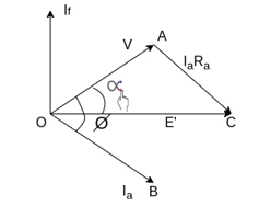
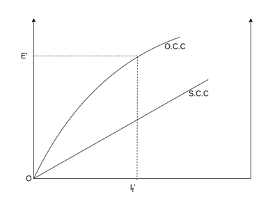
Fig 7 MMF Method
5) From the short circuit characteristic determine the field current  required to circulate the rated current on short circuit. This is the field current required to overcome the synchronous reactance drop
  Draw the field current
  in phase opposition to current
  Thus
Thus 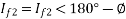 .
.
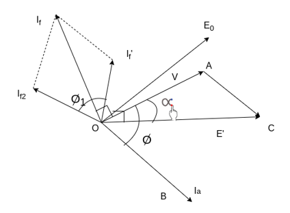
Fig 8 field current  in phase opposition to current
6) Determine the phasor sum of field current  This gives resultant field current
  which would generate a voltage
  under no load conditions of the alternator.
The open circuit emf  is found from the open circuit characteristic.
7) The regulation of the alternator is found from the relation.
Regulation =
Ampere turn method with  neglected
The phasor diagram at lagging p.f. Cos With
With  neglected.
Here
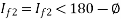


A 3-phase star connected 1000 KVA ,2000V,50Hz alternator gave the following open circuit and short circuit test readings
Field current | A | 10 | 20 | 25 | 30 | 40 | 50 |
O.C. Voltage | V | 800 | 1500 | 1760 | 2000 | 2350 | 2600 |
S.C. Armature current | A |
| 200 | 250 | 300 |
|
|
The armature effective resistance per phase is 0.2 Ω
Draw the characteristic curves and determine the full load percentage reg. At 0.8 power factor lagging and leading.
O.C.C and S.C.C are shown
The phase voltage in volts are
462, 866, 1016, 1155, 1357, 1501,
Full load phase voltage= 


a) Lagging p.f. Of 0.8


From the o.c.c. The field current required to produce the voltage of 1201.7 V is 32 A. Therefore 
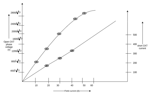
And from the s.c.c. The field current required to produce full load current of 288.7A is 29 A. Therefore  is 29 A. For

And


 A
A
From the o.c.c. The open ckt phase voltage corresponding to the field current of 54.18 A is 1559 V
Therefore, percentage voltage regulation=
=34.94%
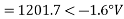
c) for leading P.F. Of 0.8


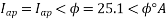
=1201.7<1.6V
From the phasor diagram
 A
A
 A
A

=28.15<148.82 A
A
From the o.c.c. To open circuit phase voltage corresponding to a field current of 28.15 A is 1098 V


Zero power factor characteristic (ZPFC)
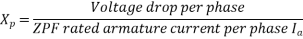
The zero-power factor characteristic (ZPFC) of an alternator is a curve of the armature terminal voltage per phase plotted against the field current obtained by operating the machine with constant rated armature current at synchronous speed and zero lagging power factor. The ZPFC is sometimes called potier characteristic after its originator.
For maintaining very low power factor, alternator is loaded by means of reactors or alternatively by an under excited synchronous motor. The shape of ZPFC is very much like that of the o.c.c. Displaced downwards and to the right.
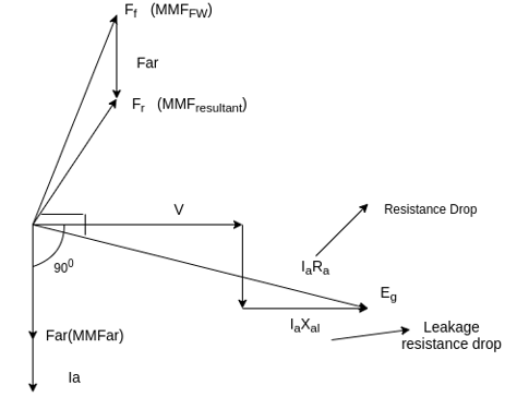
Fig 9 ZPF Characteristics
The terminal phase voltage V is it taken as the reference phasor. At zero power factor lagging, the armature current  lags behind V by 90°. Draw
  parallel to
  perpendicular to
 is the generated voltage per phase.
 armature reaction mmf. It is in phase with
 =mmf of the main field winding
 = resultant MMF
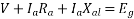
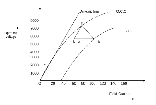
Potier triangle
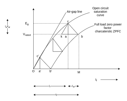
Fig 10 Potier Triangle
Construction
1) Take a point b on the ZPFC preferably well upon the knee of the curve.
2) Draw bk equal to b'O (b' is the point for zero voltage, full load current) that is ob' is the short circuit excitation, 
3) Through k draw kc parallel to oc' to meet o.c.c. In c.
4) Drop the perpendicular ca on to bk.
5) Then to scale, ca is the leakage reactance drop  And ab is the armature reaction mmf
  or field current
  equivalent to armature reaction mmf at rated current.
On the ZPFC curve point b corresponding to rated terminal voltage V and a field current of OM 
 for this condition of operation, the armature reaction MMF has a value expressed in equivalent field current of LM=
 then the equivalent field current of the resultant MMF would be OL=
This field current OL would result in a generated voltage  from the no load saturation curve.
Since for lagging PF operation

The vertical distance a.c. Must be equal to the leakage reactance voltage drop  where
where  is the rated armature current.
The triangle formed by the vertices a, b, c is called the potier triangle. For all conditions of operation with rated armature current at 0 lagging power factor of the same potier triangle must be located between the terminal voltage V point on the ZPFC and the corresponding  point on the o.c.c.
The effect of field leakage flux in combination with the armature leakage flux gives rise to an equivalent leakage reactance  , known as potier reactance. It is greater than the armature leakage reactance.

For cylindrical rotor machines, potier reactance  is approximately equal to leakage reactance
  in salient pole machines,
  may be as large as three times
Assumptions
The assumptions are made in potier method
1) The armature resistance  Is neglected.
2) The o.c.c. Taken on no load accurately represents the relation between MMF and voltage on load.
3) The leakage reactance  is independent of excitation.
4) The armature reaction MMF is constant.
It is not necessary plot the entire ZPFC for determining  experimentally only two points b and b' are sufficient.
Point b corresponds to a field current which gives the rated terminal voltage while ZPF load is adjusted to draw rated current.
Point b' corresponds to the short circuit condition (V=0) on the machine. Thus ob' is the field current required to circulate the short circuit current equal to rated current.
Key takeaway
The phasor diagram for lagging power  is drawn as shown in the phasor diagram
OA =V=terminal voltage at full load.
It is taken as a reference phasor and drawn horizontally.
OB= =full load current lagging behind V by an angle
 is the power factor of the load.
AC=voltage drop  in the armature resistance (if
  Is given). It is drawn parallel to
CD= leakage reactance voltage drops.
It is perpendicular to AC. Join OD. It is representing the generated EMF 
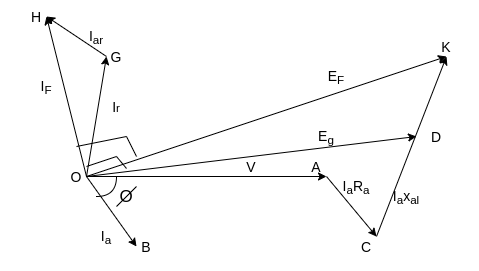
Fig 11 Phasor diagram for lagging power 
Find the field excitation current  corresponding to this generated EMF
  from the o.c.c.
Draw OG (equal to  perpendicular to OD)
Draw GH parallel to load current OB to represent excitation equivalent to full load armature reaction  . OH gives the total field current
If the load is thrown off, then terminal voltage will be equal to generated EMF and corresponding to field excitation OH.
Determine the EMF  =OK corresponding to field excitation OH from the o.c.c. Phasor OK will lag behind phasor OH by 90°. DK represents the voltage drop due to armature reaction.
Example
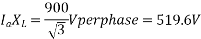
1) 5000 KVA, 6600V,3 phase, star connected alternator has resistance of 0.075Ω per phase. Estimate by zero power factor method the regulation for a load of 500 A at power factor
a) Unity
b) 0.9 leading
c) 0.71 lagging
From the following open circuit and full load, zero power factor curves.
Field current A | Open circuit terminal voltage, V | Saturation curve zero Pf, V |
32 | 3100 | 0 |
50 | 4900 | 1850 |
75 | 6600 | 4250 |
100 | 7500 | 5800 |
140 | 8300 | 7000 |
Draw a horizontal line at rated line voltage of
6600V to meet the ZPFC at b. On this line take bk=ob'=32A
Ob' is the field current required to circulate full load current on S.C.
Draw line KC parallel to oc' (the initial slope of the o.c.c.) to meet the o.c.c. At c.
Draw the perpendicular ca on the line kb. Hence abc is the potier's triangle.
Ab=field current required to overcome armature reaction on load

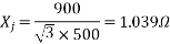
And ac=900V (line to line)
 per phase
Therefore, leakage impedance voltage drops

Unity power factor
Take  as reference phasor
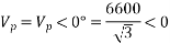


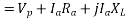

 V
V

=672.5V
From the o.c.c. The field current corresponding to the line voltage of 6125 V is 78 A. This current lead  by 90°
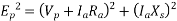
We have

From the o.c.c. Corresponding to a field current of 85A, the voltage 

=4041.5V
Therefore, voltage regulation=
=6.06%
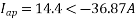
b) 0.9 PF leading


=3810.6+(500<25.84) *(0.075+1.039j)
=3617.92+483.90j
=3650.13<7.6° V

=6321.9 V
From the o.c.c. The field current corresponding to the line voltage 6321.9 V is 71 A
This current leads  by 90°
=71<97.61°
The current  is in phase with


=71<97.61-25<25.84
From the o.c.c. Corresponding to a field current of 67.6A, the voltage
Voltage regulation=
=-9.1%
C) 0.71 of lagging


=3810.6<0+(500<-44.77) (0.075+1.039j)
=4203.087+342.403j


From the o.c.c. The field current corresponding to the line voltage 7304V is 95A

From the o.c.c. Corresponding to field current of 115A

Voltage regulation = 
=19.7%
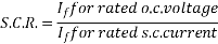
The short circuit ratio of the synchronous machine is defined as the ratio of the field current required to generate rated voltage on open circuit to the field current required to circulate rated armature current on short circuit.
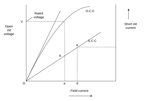
Fig 13 Short Circuit Ratio

Since triangles oab and ode are similar
S.C.R. =Oa/Od =ab/de
The direct axis synchronous reactance  is defined as the ratio of open circuit voltage for a given field current to the armature short circuit current for the same field current.

Per unit value of  is given by
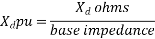
Base impedance


Significance of short circuit ratio:
It affects the operating characteristic physical size and cost of the machine. With the low value of the S.C.R. Asynchronous generator has a large variation in terminal voltage with a change in load. That is the machine is very sensitive to load variations. In order to keep the terminal voltage constant, field current is to be varied over a wide range.
A machine with a low short circuit ratio is less stable when operating in parallel with other generators. What the armature current under short circuit conditions is small. For a low short circuit ratio.
A synchronous machine with high value of short circuit ratio has a better voltage regulation and improved steady state stability limit but the short circuit fault current in the armature is high.
The size and cost of the machine are also affected by the short circuit ratio. For a synchronous machine the excitation voltage  is given by
 field flux per pole
Also, synchronous inductance

 Air gap reluctance or air gap length
It follows that the SCR may be increased by increasing the length of the air gap. With increased air gap length, the field mmf is to be increased for the same  .
.
In order to increase the field mmf either field current  or the number of field turns
  is to be increased this requires greater height of field poles. Consequently, the overall diameter of the machine increases. Thus, a large SCR will increase the size, weight and cost of the machine.
Cylindrical rotor machine- 0.5 to 0.9
Salient pole machines- 1.0 to 1.5
Key takeaway
A synchronous machine with high value of short circuit ratio has a better voltage regulation and improved steady state stability limit but the short circuit fault current in the armature is high.
The size and cost of the machine are also affected by the short circuit ratio. For a synchronous machine the excitation voltage  is given by

 field flux per pole
Parallel operation of alternators:
Electric power systems are interconnected for economy and reliable operation. Interconnection of AC power systems requires synchronous generators to operate in parallel with each other. Energy generating stations two or more generators are connected in parallel. In an interconnected system forming a grid, the alternators are located at different places. They are connected in parallel by means of Transformers and transmission lines.
An arrangement of generators for parallel operation enables a plant engineer to adjust the machine for optimum operating efficiency and greater reliability. As the load increases beyond the generated capacity of the connected units, additional generators are paralleled to carry the load.
Similarly, as the load demands falls of one or more of the machines are generally taken off the line to allow the units to operate at a higher efficiency.
Reasons of parallel operations
1) Several alternators can supply a bigger load than a single alternator.
2) During a period of light load, one or more alternators may be shut down, and the remaining operate at or near full load and thus more efficient.
3) When one machine is taken out of service for its scheduled maintenance and inspection, the remaining machines maintain the continuity of supply.
4) If there is a breakdown of a generator there is no interruption of the power supply.
5) In order to meet the increasing future demand of load more machines can be added without disturbing the original installation.
6) the operating cost and cost of energy generated are reduced when several generators operate in parallel.
Thus, parallel operation of alternator ensures greater security of supply and enables overall economic operation.
Conditions necessary for paralleling alternators
The most synchronous machine will operate in parallel with other synchronous machines and the process of connecting one machine in parallel with another machine or with an infinite bus bar system is known as synchronizing.
Those machines already carrying load are known as running machines, while the alternator which is to be connected in parallel with the system is known as the incoming machine.
Before the incoming machine is to be connected to the system the following condition should be satisfied.
1) The phase sequence of the bus bar voltages and the incoming machine voltage must be the same.
2) The bus bar voltages and the incoming machine terminal voltage must be in phase.
3) The terminal voltage of the incoming machine should be equal to that of the alternative with which it is to be run in parallel or with the bus bar voltage.
4) The frequency of the generated voltage of the incoming machine must be equal to the frequency of the voltage of the live bus bar.
Key takeaway
Electric power systems are interconnected for economy and reliable operation. Interconnection of AC power systems requires synchronous generators to operate in parallel with each other. Energy generating stations two or more generators are connected in parallel. In an interconnected system forming a grid, the alternators are located at different places. They are connected in parallel by means of Transformers and transmission lines.
Synchronizing procedure
A stationary alternator must not be connected to live bus bar because the induced EMF is zero at stand still and a short circuit will result.
1) Synchronizing lamps
A set of three synchronizing lamps can be used to check the conditions for paralleling the incoming machine with other machines. The dark lamp method along with a voltmeter used for synchronizing low power machines.
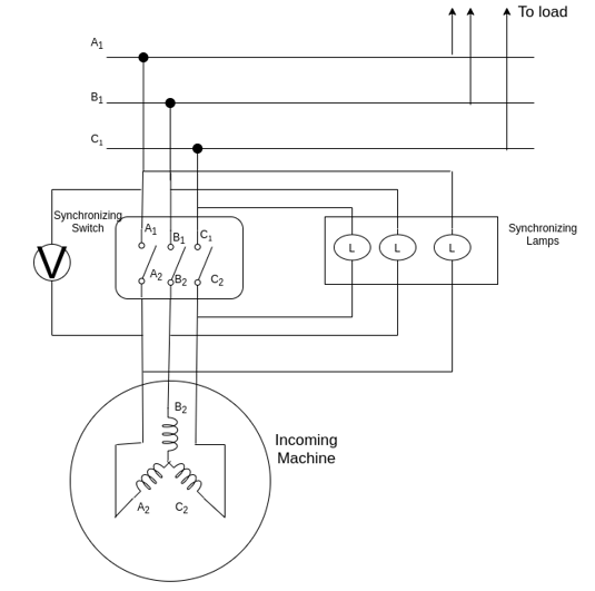
Fig 14 Synchronization Lamp
The prime mover of the incoming machine is started and brought up to near its rated speed. The field current of the incoming machine is adjusted so that its terminal voltage becomes equal to the bus voltage.
Three lamps flicker at a rate equal to the difference in the frequencies of the incoming machine and the bus. If the phases are properly connected all the lamps will be bright and dark at the same time. If this is not the case, then it means that the face sequences are not correct. In order to correct the phase sequence to leads of the line of the incoming machine should be interchanged.
The frequency of the incoming machine is adjusted until the lamps flicker at a very slow rate, usually one dark period per second.
After finally adjusting the incoming voltage, the synchronizing switch is closed in the middle of their dark period.
Since the voltage across the lamps varies from zero to twice the phase voltage the lamps of suitable rating must be used.
Advantages
1) The method is cheap
2) The proper phase sequence is easily determined
Disadvantages
1) Since the lamps become dark at about half their rated voltage it is possible that the synchronizing switch might be closed when there is a considerable phase difference between the machines. This may result in high circulating current to damage the machines.
2) The lamp filaments might burn out.
3) The flicker of the lambs does not indicate which machine has the higher frequency.
Three bright lamp methods
In this method the lamps are connected across the phases, that is  is connected to
  ,
,  is connected to
  and
and  is connected to
  . If all three lamps get bright and dark together than the phase sequences are the same. The connect instant of closing the synchronizing switch in the middle of the bright period.
Two bright 1 dark lamp period
In this method one lamp is connected between corresponding faces while two others are cross connected between the other two phases.
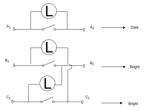
Fig 14 Three Big Lamp Method
The prime mover of the incoming machine is started and the alternator is brought up to near its rated speed.
The incoming machine excitation is now adjusted, until the incoming machine induced voltages  are equal to the bus bar voltages
The connect moment to close the switch is obtained at the instant when the straight connected lamp is dark and the cross connected lamps are equally bright.
If the phase sequence is incorrect no such instant will occur as the cross connected lamps, will in effect, be straight connected and all the lamps will be dark
Simultaneously
A voltmeter  is connected across the strait connected lamp and the synchronizing switch is closed when the voltmeter reading is zero.
4 paralleling smaller machines in power stations three lamps along with the synchro scope are used.
For synchronizing very large machines in power stations, the whole procedure is done automatically by computer.
Synchronizing by a synchro scope
The phase sequence of the generator is usually checked carefully at the time of its installation.
Condition 1 and 2 are issued by means of a synchro scope, which compares the voltages from one phase of the incoming machine with that of the corresponding phase of the three phase system.
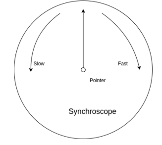
Fig 15 Synchroscope
The position of the pointer of the synchronous scope indicates the phase difference between the voltages of the incoming machine and the infinite bus.
When the frequencies are equal, the pointer is stationary and when the frequencies differ the pointer rotates in one direction or the other.
The direction of motion of the pointer shows whether the incoming machine is higher or lower than that of the infinite bus.
It is to be noted that a synchro scope check, the relationships only on the one phase. It gives no information about phase sequence.
Key takeaway
Three lamps flicker at a rate equal to the difference in the frequencies of the incoming machine and the bus. If the phases are properly connected all the lamps will be bright and dark at the same time. If this is not the case, then it means that the face sequences are not correct. In order to correct the phase sequence to leads of the line of the incoming machine should be interchanged.
Synchronizing power and synchronizing torque coefficients
Synchronous machine whether a generator or a motor when synchronized to infinite bus bar has an inherent tendency to remain in synchronism.
Consider a synchronous generator transferring a steady power  at a steady load angle
  . Suppose that due to transient disturbance the rotor of the generator accelerates so that the load angle increases by an angle
  . The operating point of the machine shifts to a new constant power line and the load on the machine increases to
  . Since this study power input remains unchanged this additional load decreases the speed of the machine and brings it back to synchronism.
Similarly, if due to transient disturbance, the rotor of the machine retards, so that the load angle decreases consequently the machine again comes in synchronism.
It is seen that the effectiveness of this correcting action depends on the change in power transfer for a given change in load angle.
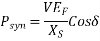
A measure of effectiveness is given by synchronizing power coefficient. It is defined as the rate at which the synchronous power P where is with the load angle  it is also called stiffness of coupling, rigidity factor, or stability factor and is denoted by
For salient pole machine
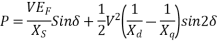
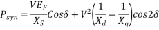
For cylindrical rotor machine neglecting saturation and stator resistance
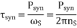
Synchronizing torque coefficient
Synchronizing power coefficient gives rise to synchronizing torque coefficient at synchronous speed. That is, the synchronizing torque is the torque which at synchronous speed gives the synchronizing power. If  in the synchronizing torque coefficient.
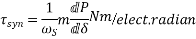
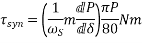
m=Number of phases of the machine.


Key takeaway
Synchronous machine whether a generator or a motor when synchronized to infinite bus bar has an inherent tendency to remain in synchronism.
Examples
Q1) Two 550kVA alternators operate in parallel to supply the following loads (i) 250kW at 0.95 power factor lag (ii) 100kW at 0.8 power factor lead One machine is supplying 200kW at 0.9 power factor lag. The power factor of the other machine must be (A) 0.89 lead (B) 0.95 lead (C) 0.95 lag (D) 0.89 lag
A1) Total KVA Supplied to Load = 𝟐𝟓𝟎 𝟎.𝟗𝟓 ∠ − 𝐜𝐨𝐬−𝟏 𝟎. 𝟗𝟓 = (250-j82.17) kVA
Total KVA Supplied to M2 = 𝟏𝟎𝟎/𝟎.𝟖 ∠ 𝐜𝐨𝐬−𝟏 𝟎. 𝟖 = (100+j75) kVA
Total KVA Supplied to M1 = 𝟐𝟎𝟎 𝟎.𝟗 ∠ 𝐜𝐨𝐬−𝟏 𝟎. 𝟗 = (200-j96.864) kVA
Using Power Conversation:
(250-j82.17) kVA + (100+j75) kVA = (200-j96.864) kVA +S2
S2 = 174.65 ∠30.814
Positive Sign Indicates Leading P.F
P.F = Cos (30.8140) = 0.8588 Lead
Q2) A round rotor generator with internal voltage E1=2.0p. u and X1=1.1p. u is connected to a round rotor synchronous motor with internal voltage E2=1.3. u and X2=1.2p.u. The reactance of the line connecting the generator to the motor is 0.5p.u. When the generator supplies 0.5 p.u. Power, the rotor angle difference between the machines will be (A) 57.42o (B) 1o (C) 32.58o (D)122.58o
A2)
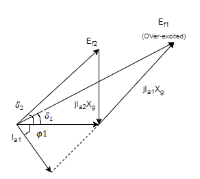
Assuming resistance of the armature to be zero. In first case, the generator is feeding a partly inductive load. It means that generator is supplying lagging power. The generator is supplying lagging power current when it is overexcited which is represented by Ef1. In second case, a capacitor is connected across the load to completely nullify the inductive current. It means the generator supplies no reactive power and unity power factor current is drawn from the generator. The excitation (Ef2) corresponding to unity. From the phasor diagram Ef1>Ef2 and as the field current approximately directly proportional to excitation, the field current has to be reduced.
Q3) The phasor diagram of the synchronous machine connected to an infinite bus is shown in Figure. The machine is acting as a: (A) Motor and operating at leading PF (B) Generator and Operating at lagging PF (C) Motor and Operating at a lagging PF (D) Generator and operating at leading PF
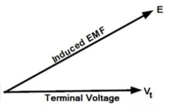
A3) The voltage regulation of an alternator is defined as the change in its terminal voltage when the full load is removed, keeping field excitation and speed constant, divided by the rated terminal voltage. So, if Vph = Rated terminal voltage Eph = No load-induced e.m.f Regulation = (Eph -Vph)/Vph The value of the regulation not only depends on the load current but also on the power factor of the load. For lagging and unity p.f. Conditions there is always a drop in the terminal voltage hence regulation values are always positive. Hence option B
Q4) Consider two alternators are running in parallel now if the excitation of the one of the alternators is changed then it will
(A) Change power factor
(B) Change frequency
(C) Reduce speed
(D) Change load demand
A4) Suppose the excitation of the alternator is decreased below normal excitation then reactive power will change and active power output (W or KW) of the alternator will remain unchanged. The under-excited alternator delivers leading current to the infinite bus bar. It is because the leading current produces an adding m.m.f to increase the under excitation. Similarly, an overexcited alternator operates at lagging power factor and supplies lagging reactive power to an infinite bus bar. Conclusion: From both of the above condition i.e., whether the excitation is increased or decreased its power factor changes. Hence option A.
Q5) A three-phase alternator is connected to a delta-delta transformer. The hysteresis and eddy current losses of the transformer are, respectively, 300 W and 400W. If the speed of the alternator is reduced by 10%, then the hysteresis and eddy current losses of the transformer will be?
A5)
Given 
Now 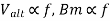 and assuming
  we have


Q6) A 6-pole, three-phase alternator running at 1000 rpm supplies to an 8-pole, three-phase induction motor which has a rotor current of frequency 2 Hz. The speed at which the motor operates is (A) 1000 rpm (B) 960 rpm (C) 750 rpm (D) 720 rpm
A16)
Given that  , therefore
 this frequency is generated by alternator
Thus 

And 
For a eight pole motor of 50Hz the speed 
The speed of induction motor
Q7) The salient-pole construction for field structure of an alternator is generally used for ................ Machine. (A) 2-pole (B) 8-pole (C) 4-pole (D) 10-pole
A7) The salient pole rotors are driven by low-speed water turbines or diesel engines. It is because the salient-pole type construction is difficult to build to withstand the stresses at high speeds. Because a salient pole rotor turns at low speed (50 to 300 r.p.m.) and because a frequency of 50 Hz is required, we must place a large number of poles on the rotor. The speed of an alternator is given as
N = 120f/P
Hence the speed of an alternator is inversely proportional to the number of poles. As discussed above the salient pole alternator turns at low speed, therefore, the number of poles required to be more.
Q8) In case of leading power factor, the terminal voltage of the alternator will: (A) Rise on removing the full load
(B) Fall on removing the full load
(C) Fall on adding the full load
(D) Rise on adding the full load
A8)
- Under the load condition, the terminal voltage of the alternator is less than the induced e.m.f(Eph). So, if the load is disconnected, Vph (per phase rated terminal voltage) will change from Vph to Eph, if flux and speed are maintained constant. This is because when the load is disconnected, Ia is zero hence there are no voltage drops and no armature flux to cause armature reaction. This change in the terminal voltage is significant in defining the voltage regulation.
- The voltage regulation of an alternator is defined as the change in its terminal voltage when the full load is removed, keeping field excitation and speed constant, divided by the rated terminal voltage.
- So, if Vph = Rated terminal voltage
- Eph = No load-induced e.m.f
- Regulation = (Eph -Vph)/Vph
- The value of the regulation not only depends on the load current but also on the power factor of the load.
- For lagging and unity p.f. Conditions there is always a drop in the terminal voltage hence regulation values are always positive.
- While for leading capacitive load conditions, the terminal voltage increases as load current increases. Hence the regulation is negative in such cases. Hence the terminal voltage will fall on removing the full-load
References:
1) M.G. Say, Performance and Design of A.C. Machines (3rd Ed.), ELBS
2) J B Gupta - Theory and performance of Electrical Machines, S K Kataria Publications
3) Samarjit Ghosh, Electrical Machines, Pearson Publication.
4) Bhag S Guru and Huseyin R Hiziroglu, Electrical Machinary and Transformer, 3rd Edition, Oxford University Press.
5) E G Janardanan, Special Electrical Machines, Prentice Hall of India.
6) Suvarnsingh Kalsi Application of high Temperature super conductors to electric power equipments (Rotating Machines) Wiley publication.


