Unit 5
Three Phase Induction Motor
There are two main parts of induction motor:
a) Stator
b) Rotor
a) Stator:
It is stationary part of induction motor. It has number of stampings. It is wound with three phase winding which is fed from 3-phase supply. The number of poles here are defined, they are selected according to the speed required. If required speed is greater than we need a smaller number of poles. The stator produces an alternating flux when fed with 3-phase supply which revolves with synchronous speed (Ns = 120f / P). The synchronous speed is inversely proportional to number of poles.
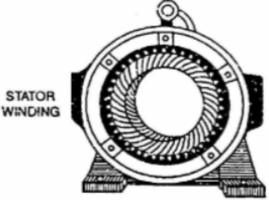
Fig. 1: Stator
b) Rotor: It is rotating part of induction motor. There are two types of rotor –
i) Squirrel cage rotor:
The rotor consists of a cylindrical core with parallel slots for carrying the rotor conductor. Each slot has one copper or aluminium bar. Each end of all bars is joined with metal ring. The entire construction resembles a squirrel cage. The rotor is not connected electrically to the supply it has induced current from stator. Almost 90% of induction motors are squirrel cage type. But is has a disadvantage of low starting torque, because the rotor bars are permanently short-circuited.
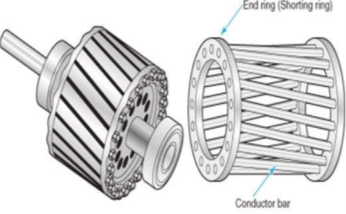
Fig. 2: Squirrel cage rotor
Ii) Phase-wound rotor:
It has laminated cylindrical core and the windings are uniformly distributed in the slots which are usually star connected. The other three winding terminals are brought out and connected to three insulated slip rings mounted on shaft with brushes resting on them. The three brushes are connected to a 3-phase star-connected rheostat as shown in Figure below.
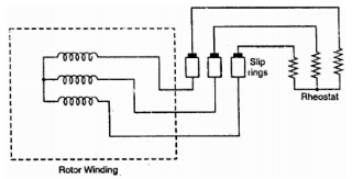
Fig. 3: 3-phase star connected
At starting, the external resistances are included in the rotor circuit to give a large starting torque. These resistances are gradually reduced to zero as the motor runs up to speed. The external resistances are used during starting period only. When the motor attains normal speed, the three brushes are short-circuited so that the wound rotor runs like a squirrel cage rotor.
Key takeaway
The stator is stationary part of machine and rotor is the rotating part.
The 3-phase windings are displaced by 120º in space, are fed by three phase currents, and displaced by 120º in time as well. They produce magnetic flux.
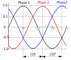
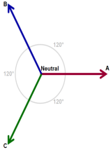
Fig. 4: Three phase winding
Let φm be the maximum value of lux. The resultant flux is the vector sum of individual fluxes φ1, φ2, φ3 due to three phases.
i) When  i.e point 0, in above graph
φ1=0 φ2= φm and φ3=
 φm
φm
φr= 2 x  φm x cos30
 φm
φm
Ii) When  (i.e blue line curve)
φ1= φm φ2=
 φm and φ3=0
The resultant flux φr= 2 x  φm x cos30
 φm
φm
The resultant flux gain is rotated clockwise through 
Iii) When  (red line curve)
φ1= φm φ2=
 and φ3=
 φm
φm
The resultant flux is φr= 2 x  φm x cos30
 φm
φm
The resultant again has same value but further rotated clockwise 
Iv) When 
φ1=0 φ2= φm and φ3=
 φm
φm
The resultant again is φr= 2 x  φm x cos30
 φm but has rotated clockwise through
Key takeaway
When 
φ1=0 φ2= φm and φ3=
 φm
φm
When 
φ1= φm φ2=
 φm and φ3=0
When  (red line curve)
φ1= φm φ2=
 and φ3=
 φm
φm
When 
φ1=0 φ2= φm and φ3=
 φm
φm
The fundamental principle of induction machine is the creation of rotating and sinusoidally distributed magnetic field in the air gap. Three phase balanced power supply is fed to the three-phase stator winding creates a synchronously rotating magnetic field. Due to relative speed between rotating flux and stationary conductors, an emf is induced. The frequency to induced emf is same as supply frequency.
As shown in below fig., the stator field is assumed to clockwise. The relative motion of rotor w.r.t stator is anticlockwise. From Right-hand rule, the direction of induced emf in rotor is outwards. By the effect of combined field as shown in fig b the rotor experiences a force tending to rotate it in clockwise direction. Hence rotor rotates in the same direction as the stator field.
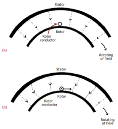
Fig. 5: Rotating Field
The speed of this rotating field is called synchronous speed. If the rotor is initially stationary, its conductors will be subjected to a changing magnetic field, inducing current in the short-circuited rotor at the same frequency. The interaction of air gap flux and rotor mmf produces torque. At synchronous speed rotor cannot have any torque.
Key takeaway
The speed of this rotating field is called synchronous speed. If the rotor is initially stationary, its conductors will be subjected to a changing magnetic field, inducing current in the short-circuited rotor at the same frequency
Slip:
The rotor can never have same speed as that of stator. If it occurs then there will not be relative speed between the two, hence no rotor emf, no rotor current and so no torque to maintain rotation. Due to this reason speed of rotor is always less than the stator field. The difference between the synchronous speed Ns and the actual speed N of the rotor is called as slip.
% slip s=
Therefore, rotor speed N=Ns(1-s).
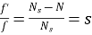
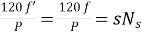
Frequency of rotor current:
When rotor is stationary its frequency is same as the supply frequency. But when rotor revolves its frequency depends upon the slip-speed. Let frequency of rotor current be f’
Ns-N=
But Ns=
Rotor current have same frequency

=
MMF produced by rotor current:
a) For standstill condition:
Let E2=emf induced per phase of rotor at standstill
R2=resistance per phase of rotor.
X2=reactance per phase of rotor at standstill=2 f1L2
f1L2
Z2=rotor impedance per phase
I2=rotor current per phase
Z2=R2+jX2
 =
=
Power Factor cosφ2= =
=
b) Rotor current at slip s:
Induced emf per phase in rotor winding at slip s is E2s=sE2
Rotor winding reactance per phase at slip s will be X2s=2 f2L=sX2
Rotor winding impedance per phase at slip s is Z2s=R2+jX2s=R2+jsX2
Rotor current at slip s, I2s=
Power factor at slip s is cosφ2s=
Key takeaway
Rotor speed N=Ns(1-s).
Power Factor cosφ2= =
=
Rotor current at slip s, I2s=
Power factor at slip s is cosφ2s=
Que) The stator of a 3-phase induction motor has 5 slots per pole per phase. If supply frequency is 50Hz. Calculate a) number of stator poles produced and total number of slots in stator. b) Speed of rotating stator flux.?
Sol: a) P=2n=2*5=10 poles
Total number of slots= 5 slots/pole/phase * 10 poles * 3 phase=150
c) Ns= =120x50/10=600rpm
Que) A 3-phase induction motor is wound for 5 poles and is supplied from 50 Hz. Calculate a) synchronous speed b) rotor speed when slip is 4% c) rotor frequency when rotor runs at 500 rpm?
Sol: a) Ns= =120x50/5=1200 rpm
b) rotor speed N=Ns(1-s) = 1200(1-0.04) = 1152 rpm
c) when rotor speed is 500 rpm, slip s=(Ns-N)/Ns= (1200-500)/1200 = 0.58
Rotor current frequency f’=sf=0.58x50=29.17 Hz
Que) A 3-phase, 50 Hz,3-pole induction motor has a slip of 4%. Calculate a)speed of rotor. B) frequency of rotor emf. If the rotor as a resistance of 2ohm, and standstill reactance of 4 ohm, calculate the power factor c) at standstill and d) at a speed of 1200rpm?
Sol: Ns= =120x50/3=2000 rpm
a) Speed of rotor N=Ns(1-s)=2000(1-0.04)=1920 rpm
b) Frequency or rotor = f’=sf=0.04x50=2Hz
R2=2ohm, X2=4ohm
Z2=R2+jX2=2+j4=4.47 63.43o ohm
c)Power factor cosφ2=0.44(lag)
Slip at speed 1200rpm s= 2000-1200/2000=0.4
Rotor impedance at slip s=0.4 is
Z2s=R2+jsX2=2+jx0.4x4=2.56 oohm
oohm
c) Power factor at 1200rpm is cos φ2s=cos38.66o=0.78(lag)
The torque developed at the moment when motor starts is called as starting torque. As we already know the motor torque Ta α φ Ia. An induction motor develops gross torque Tg due to gross rotor output Pm. Then in terms of rotor input
Tg=
In terms of rotor output the gross torque is Tg=
Due to rotor friction and windage losses the shaft torque Tsh is less than Pm
Tsh= (N, Ns are in rpm)
Tg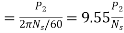 N-m
N-m
Tsh =
= N-m
N-m
For induction motor the torque is also proportional to the product of flux per stator pole and the rotor current, in addition to the power factor.
Starting Torque
T α φ I2 cos φ2
Or T=k φ I2 cos φ2
I2=rotor current at standstill
φ2=angle between rotor emf and rotor current
E2=rotor emf at standstill.
Also, E2 α φ
So, T α E2I2 cos φ2
T=k1 E2I2 cos φ2
The starting torque Tst= k1 E2I2 cos φ2
From above section we know,  =
= , cosφ2=
 =
=
Tst= k1 E2.  =
=
For supply voltage constant, flux and E2 both are constant
Tst=
k1=
Therefore, Tst=
Torque-Slip Relation:
The torque slip characteristics is shown below. For low value of slip the curve is approximately a straight line. As slip increases the torque also increases and becomes maximum when s= R2/X2. This torque is called pull-out or breakdown torque Tb. From above section we already know
T=
T α 
When slip increases more with motor load R2 becomes negligible. So, for large value of slip
T α  α
α 
Key takeaway
Tg=
Tg N-m
N-m
Tst=
T=
Torque of rotor in running condition is given as
T= = k1
= k1 
Condition for maximum torque will be obtained by differentiating the above equation, we will get 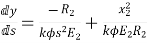 =0
=0
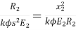
 =s2
=s2 
s=R2/X2
When rotor resistance per phase is equal to rotor reactance per phase under running condition, we have maximum torque. The above torque equation can be written as
Tmax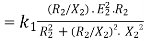 =k1
=k1
k1=
Hence, maximum torque is given as
Tmax =  N-m
N-m
Que) A 3-phase induction motor star connected rotor has an induced emf of 70volts between slip rings at standstill on open circuit. The rotor has a resistance and reactance per phase of 1ohm and 5ohm respectively. Calculate current/phase and power factor when slip rings are short circuited?
Sol: Standstill emf/rotor phase=70/
Rotor impedance/phase= ohm
ohm
Rotor current/phase=40.4/5.09=7.92A
Power factor cosφ=0.99
Que) A 3-phase induction motor star connected rotor has an induced emf of 70volts between slip rings at standstill on open circuit. The rotor has a resistance and reactance per phase of 1ohm and 5ohm respectively. Calculate current/phase and power factor when slip rings are connected to star connected rheostat of 2ohm?
Sol: Rotor resistance/phase=2+1 = 3 ohm
Rotor impedance/phase = = 5.83 ohm
Rotor current/phase = (70/ )/5.83 = 6.93A
Cosφ=3/5.83=0.514
Que) A 6-pole, 3-phase induction motor operates from a supply whose frequency is 50Hz. Calculate i) speed at which the magnetic field of stator is rotating. Ii)speed of rotor when slip is 4%. Iii)frequency of rotor current when slip is 3%?
Sol: i) Stator revolves at synchronous speed. So, Ns=120f/P=120 x 50/6=1000rpm
Ii)rotor speed N=(1-s)Ns=(1-0.04) x 1000=960rpm
Iii)frequency of rotor current f’=sf=0.03 x 50=90rpm
The below curve can be divided into three regions.
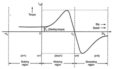
Fig. 6: Torque-Slip Characteristics
i) Motoring Region(0≤s≤1): The induction motor rotates in the same direction as that of the field. Here the speed decreases and torque increases till breakdown torque is reached. In this region air-gap flux is nearly constant. After breakdown torque Tmax, torque decreases and slip increases.
Ii) Generating Region(s<0): In this machine operates as a generator. The rotor rotates at a speed greater than synchronous speed in same direction as that of rotating magnetic field. Due to super synchronous speed the slip becomes negative and creates negative regenerative torque.
Iii) Plugging Region(1≤s≤2): Here slip becomes greater than unity. So, motor rotates in the opposite direction of the rotating magnetic field. Here the stator field is reversed by changing the phase sequence of input supply, due to this the direction of rotating magnetic field also changes. Here torque is positive but speed is negative. So, plugging torque appears as breaking torque. This method of breaking is called plugging.
Key takeaway
Motoring Region(0≤s≤1), Generating Region(s<0) and Plugging Region(1≤s≤2)
A high rotor resistance will provide a high starting torque, leading to rapid acceleration of the mechanical system. This is desirable because short acceleration times reduce the stress on the power system caused by high starting currents. While high starting torques are desirable, high rotor resistance results in a relatively high slip during normal running operation. The high resistance causes increased losses and reduced efficiency during normal operation. For most applications, it is desirable to have high starting torque and high efficiency at rated speed. However, designs with high starting torque will have low efficiency at rated speed and designs with high efficiency will have low starting torque.
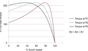
Fig. 7: Torque-Speed characteristics
Key takeaway
For most applications, it is desirable to have high starting torque and high efficiency at rated speed.
Starting torque and maximum torque
Starting torque is given as Tst= (section 5.5)
Maximum Torque Tmax =k1 
Tst α 
Tmax α 
 =
= =
=  =
=
a= =
= per phase.
Full load torque and maximum torque
Let sf be slip for full load torque.
Tf α 
Tmax α 
Dividing numerator and denominator by 
 =
=
Key takeaway
Starting torque and maximum torque
 =
= =
=  =
=
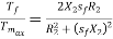
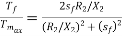
Full load torque and maximum torque
 =
=
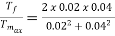
Que) A 12-pole, 3-phase, 600V, 50Hz, star connected induction motor has rotor-resistance and standstill reactance of 0.04 and 0.6 ohm per phase respectively. Calculate i) speed of max. Torque ii) ratio of full load torque to max torque, if full load speed is 495rpm?
Sol: Ns=120f/P=120 x 50/12=500 rpm
For r=0.04 and x=0.6 ohm, slip torque is
Smt=a=r/x=0.04/0.6=0.067
i) Speed =(1-Smt)N=(1-0.067) x 500=466.67 rpm
Ii) Full load speed = 495rpm, slip=0.01, at full-load
 =
= =
= =0.29
=0.29
Que) A 3-phase 400/200V, Y-Y connected wound rotor induction motor has 0.05 ohms resistance and 0.2 ohm stand still reactance per phase. Find the additional resistance required in the rotor circuit to make starting torque equal to the maximum torque of motor?
Sol: 
Given Tst=Tmax
1= , a=1
, a=1
a=
1=
r=0.15 Ω
Que: A 50hz ,6-pole induction motor has full load slip of 4%. The rotor resistance/phase = 0.02ohm and standstill reactance/phase=0.1 ohm. Find the ratio of maximum to full load torque and the speed at which the maximum torque occurs?
Sol: 
a=R2/X2=0.02/0.1=0.02
 = 0.8
= 0.8
Ns = 120 x 50/6 = 1000rpm, sm= a(for maximum torque) = 0.02
N = (1-0.02) x 1000 = 980rpm
In general, we can categorise losses as:
i) Constant losses: They remain constant over the normal working range of induction motor. By no-load test we can find these losses. The losses falling in this category are Iron or core loss, Mechanical Loss and Brush Friction loss.
a) Iron or core loss: The core losses depend on the frequency of supply voltage. As the frequency of rotor is always less than that of stator. Hence, core loss in rotor is less compared to that of stator. The core loss can be further classified as hysteresis and eddy current losses.
b) Mechanical and Brush Friction Loss: These are low at starting and increases with increase in speed. In induction motor speed is usually constant hence these losses also remain constant. Mechanical losses occur in bearings and brush friction losses occur in wound rotor induction motor.
Ii) Variable losses: These losses occur due to current flowing in stator and rotor windings. As the load changes, the current flowing in rotor and stator winding also changes and hence these losses also change. Therefore, these losses are called variable losses. The copper losses are obtained by performing blocked rotor test on three phase induction motor.
Key takeaway
The losses are constant loss, iron loss, mechanical and brush friction loss and variable loss.
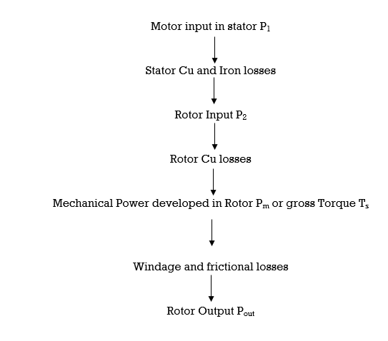
Stator input P1=stator output + stator losses
P2=stator output
Rotor gross output Pm= P2 – rotor cu loss
The rotor output is converted to mechanical energy producing gross torque Tg. Due to windage and friction losses in rotor some torque is lost. The remaining is shaft torque Tsh.
Tg = 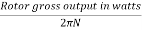 (1)
(1)
When no cu loss than rotor output is equal to rotor input.
Tg =  (2)
(2)
But Pm = Tg ω=Tg * 2
P2 = Tg ωs=Tg * 2 s (3)
s (3)
Rotor cu loss= P2 - Pm=Tg x 2 s-
s- (4)
(4)
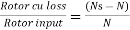 =s
=s
Rotor cu loss = s x rotor input=sP2 (5)
Pm=P2-rotor cu loss=input – s x rotor input
=(1-s) input P2 (6)
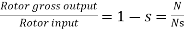
Therefore, 
 =
= (7)
(7)
Key takeaway
Pm=P2-rotor cu loss=input – s x rotor input
=(1-s) input P2
Que) The power input to a rotor of 440V, 50Hz, 6-pole, 3-phase, induction motor is 60kW. The rotor force is observed to make 80 alterations per minute. Calculate i) slip ii) rotor speed iii) rotor cu loss per phase?
Sol: 80 alterations per minute=80/60 cycles per second=1.333Hz=sf
i)slip=1.333/50=0.027 P.u.=2.7%
Ii)Rotor speed N=(1-s) Ns = (1-0.027) x 1000=973.33rpm
Ns=120f/P=120 x 50/6=1000rpm
Iii)rotor cu loss/phase= =
= =0.54kW
Que) The power input to a 3-phase induction motor is 80kW. The stator loss is total 1kW. Find the mechanical power developed and the rotor cu loss per phase if the slip is 3%?
Sol: P2= stator input – stator losses=80-1=79kW
Pm=(1-s)P2==(1-0.03) x 79=76.63kW
Total rotor cu loss=sP2=0.03 x 79=2.37kW
Rotor cu loss per phase=2.37x1000/3=790W
Que) The power input to a rotor of a 400V, 50hz,6-pole, 3-phaseinduction motor is 15kW. The slip is 4%. Calculate i) frequency of rotor current. i)rotor speed. Iii)rotor cu loss iv) rotor resistance/phase if rotor current is 50A?
Sol: i) frequency of rotor current=sf=0.04 x 50=2Hz
Ii) Rotor speed N=(1-s) Ns=(1-0.04) x 1000=960rpm
Ns=120f/P=120 x 50/6=1000rpm
Iii) rotor cu loss=s x rotor input=0.04 x 15=0.6kW
Iv)rotor cu loss/phase=0.6 x 1000/3=200W
602R2=200
R2=0.055Ω
Rotor Efficiency= =
=
3-phase induction moor efficiency= =
=
References
[1] Edward Hughes “Electrical Technology”, ELBS, Pearson Education.
[2] Ashfaq Husain, “Electrical Machines”, Dhanpat Rai& Sons.
[3] S. K. Bhattacharya, “Electrical Machine”, Tata McGraw Hill publishing Co. Ltd, 2nd Edition.
[4] Nagrath & Kothari, “Electrical Machines”, Tata McGraw Hill.
[5] Bhag S Guru, Husein R. Hiziroglu, “Electrical Machines”, Oxford University Press.
[6] K Krishna Reddy, “Electrical Machines- I and II”, SCITECH Publications (India) Pvt. Ltd. Chennai.


