UNIT 1
Transformers
A transformer is a stationary device which works on the principle of Mutual Induction. It is used to transform electric power from one circuit to another having same frequency. It can lower or higher the value of voltage in any circuit but in correspondence to change in current.
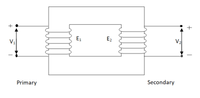
An ideal transformer has no losses i.e. its winding has no magnetic leakage and no ohmic resistance. Hence, an ideal transformer has only two purely inductive coils wound on a loss-free core.
Fig. 1: Ideal Transformer
For above transformer when secondary is open and primary is having input sinusoidal voltage V1. An alternating current flow due to difference in potential. As primary coil is purely inductive so, Iµ current is drawn through it. This current is very small and logs V1 by 900.
The current Iµ produces magnetic flux φ and hence are in same phase. The flux is linked with both the windings and hence, self-induced emf is produced E1 which is equal and opposite of V1. Similarly, E2 is induced in secondary which is mutually induced emf E2 is proportional to rate of change of flux and number of secondary windings.
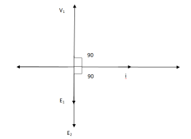
The phasor is shown below.
Fig. 2: Phasor for Ideal Transformer
Emf Equation of Transformer:
N1 = No of primary turns
N2 = No of secondary turns
Φm = max flux in cone (wb)
Φm = Bm x A
f = Frequency of input(ac) Hz
Average rate of change of flux
= Φm / ¼
= 4 ΦmF volts
Average emf per turn = 4F ΦmV
As Φ varies sinusoidally rms value of induced emf is given as
Form factor = r.m.s value / average value = 1.11
r.m.s value of emf/turn = 1.11 x 4f Φm
= 4.44 f Φm volt
r.m.s value of induced emf in primary winding
= (induced emf/turn) x No of primary turns
E1 = 4.44 fN1 Φm
E1 = 4.44 fN1BmA
r.m.s emf induced in secondary
E2 = 4.44 fN2 Φm
E2 = 4.44 fN2BmA
E1/E2 = N1/N2 = K
K – voltage transformation
(i). If N2 > N1 i.e K > 1 STEP UP TRASFORMER
(II). If N1 > N2 i.e K<1 STEP DOWN TRASFORMER
FOR Ideal Transformer
V1 I1 = V2 I2 = 1/K
Hence, current is inversely proportional to the voltage transformation ratio.
Key takeaway
r.m.s value of induced emf in primary winding E1 = 4.44 fN1 Φm
r.m.s emf induced in secondary E2 = 4.44 fN2 Φm
(i). If N2 > N1 i.e K > 1 STEP UP TRASFORMER
(II). If N1 > N2 i.e K<1 STEP DOWN TRASFORMER
FOR Ideal Transformer
V1 I1 = V2 I2 = 1/K
They are compact in size. They have minimum losses. They have adequate mechanical strength. In this a simple rectangular core is used with cylindrical coils which are either circular or cylindrical form.
Q1>. A 25 KVA transformer has 500 turns on primary and 50 on secondary. The primary is connected to 2000V, 50 Hz supply. Find full load primary and secondary currents, the secondary emf and max flux in core. Neglect leakage drop and no load primary current.
Sol: K = N2/N1 = 50/500 = 1/10
I1 = 25,000/2000 = 12.5 A
I2 = I1/K = 10 x 12.5 A = 125 A
Emf/turn on primary side = 2000/500 = 4 V
E2 = KE1
E2 = 4 x 50 = 200 v
E1 = 4.44fN1 Φm
2000 = 4.44 x 50 x 500 x Φm
Φm = 18.02 m Wb
They have magnetic cores with a ring or donut (toroidal) shape. Because of the core design the electrical performance increases effectively. Due to the symmetry the leakage flux outside the core is low, hence it is more efficient.
USES: Used in power supplies, inverters and amplifiers i.e. majorly in TVS, radio, computers and audio system.
Topic covered in below section.
1.6.1 Transformer with winding Resistance but no magnetic leakage
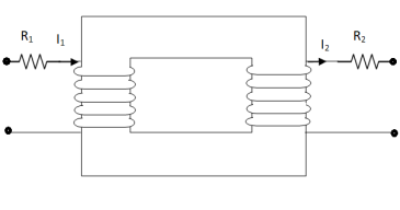
A practical transformer is supposed to have some resistance in both windings and due to this resistance, there is some voltage drop in both winding.
Fig. 3: Transformer with Resistance
V2 = E2 – I2R2
E1 = V1 – I1R1
V2 = Secondary terminal voltage
E2 = Secondary induced emf
R2 = Secondary resistance
E1 = Primary induced emf
V1 = Primary terminal voltage
R1 = Primary Resistance
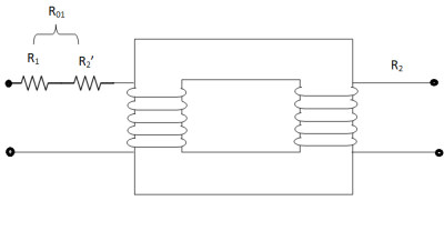
 If both the terminal resistances are concentrated on same side, it helps to reduce the calculations. So, the equivalent circuits referred to primary side and secondary side are shown below.
Fig. 4: Equivalent resistance referred to primary
I12 R’2 = I22 R2
R’2 = (I2/I1)2 R2
R’2 = R2/K2
R01 = R1 + R’2
R01 = R1 + R2/K2
The total equivalent resistance referred to primary is
R01 = R1 + R2/K2
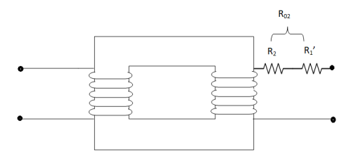
 Similarly, effective resistance referred to secondary is shown below,
Fig. 5: Equivalent resistance referred to secondary
I22R’1 = I21 R1
R’1 = (I1/I2)2 R1
R’1 = K2R1
Total transformer resistance referred to secondary
R02 = R2 + R’1
R02 = R2 + K2R1
1.6.2 Leakage Flux
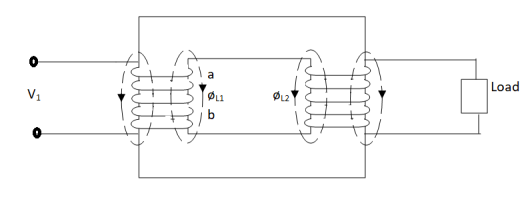
The flux linked with primary does not links with the secondary. Some part of the flux completes its magnetic circuit by passing through air, rather than core. This is known as primary leakage flux.
Fig. 5: Leakage flux in Transformer
From above figure we can conclude that
(i). Leakage flux produced in primary exists between a and b. The flux φL1 is in phase with I1.
(ii). φL1 induces and emf eL1 in primary and not in secondary windings.
(iii). Leakage flux in secondary is produced between c and d. The flux φL2 is in phase with I2 and produces induced emf eL2 in secondary only.
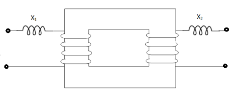
We can also say that a transformer with magnetic leakage is equivalent to an ideal transformer with inductive coils connected in both primary and secondary circuits.
Fig. 6: Ideal transformer with inductive coils
X1 = eL1/I1, X2 = eL2/I2
X1 – Primary leakage reactance
X2 – Secondary leakage reactance
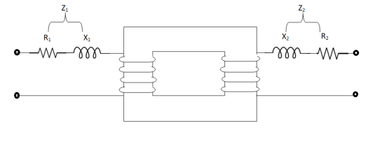
1.6.3 Transformer with Resistance and Leakage Reactance
Fig. 7: Transformer with resistance and leakage reactance
Z1 = √R21 + X21
Z2 = √R22 + X22
Z1 – Primary impedance
Z2 – Secondary impedance
But there is I1X1 and I1R1 drop in primary so,
V1 = E1 + I1(R1 + jX1)
V1 = E1 + I1Z1
Similarly, for secondary side,
E2 = V2 + I2 (R2 + jX2)
E2 = V2 + I2 Z2
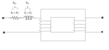
As in above article we have seen that resistance can be transferred to either sides of transformers to reduce the calculations. Similarly, we can do with the reactance also,
Fig. 8: Equivalent resistance and reactance referred to primary
Z01 = √R201 + X201
X’2 = X2/K2
R’2 = R2/K2
X01 = X1 + X’2 = X1 + X2/K2
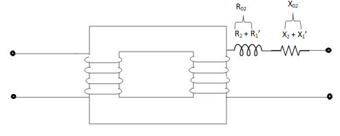
For secondary we have
Fig. 9: Equivalent resistance and leakage reactance referred to secondary
Z02 = √R202 + X202
X’1 = K2X1
X02 = X2 + X’1 = X2 + K2X1
R02 = R2 + R’1 = R2 + R1K2
Key takeaway
For Primary windings
Z01 = √R201 + X201
For Secondary windings
Z02 = √R202 + X202
1.6.4 Their effect on voltage regulation and efficiency
VOLTAGE REGULATION OF TRANSFORMER:
It can be explained in terms of various parameter of transformer.
(1). When transformer has constant primary voltage.
In this case secondary voltage decreases
0V2 = No-load secondary terminal voltage
0V2 = E2 = EK1 = KV1
V2 = secondary voltage on full-load.
Voltage Regulations is change in secondary terminal voltage from no-load to full load per unit full load voltage.
% regn down = 0V2 – V2/0V2 x 100
% regn up = 0V2 – V2/V2 x 100
(2). Voltage regulation in terms of primary values.
The secondary no-load terminal voltage as referred to primary is E’2 = E2/K = E1 = V1
For secondary full load voltage referred to primary is V’2 = V2/K
% regn = V1 – V’2/V1 x 100
% regn = I1 R01 cosφ + I1 X01 sinφ / V1 x 100
(3). As the transformer is loaded, to maintain a constant output voltage, the primary voltage should be increased. Here the regulation is given as
% regn = V’1 – V1 / V1 x 100
It can also be defined as the change in primary voltage from no-load to full-load at given power factor to maintain a constant output per unit primary voltage.
Key takeaway
The total equivalent resistance referred to primary is
R01 = R1 + R2/K2
For secondary full load voltage referred to primary is V’2 = V2/K
% regn = V1 – V’2/V1 x 100
% regn = I1 R01 cosφ + I1 X01 sinφ / V1 x 100
% regn = V’1 – V1 / V1 x 100
Q. A – 100 KVA transformer has 500 turns on primary and 80 turns on secondary. The primary and secondary resistances are 0.3 and 0.01 Ω respectively and the corresponding leakage reactances are 1.1 and 0.035 Ω. The supply voltage is 2400 V. Find
(i). Equivalent impedance referred to primary
(ii). Voltage regulation and the secondary terminal voltage for full load having pf 0.8 lagging?
Sol. Equivalent impedance referred to primary
Z01 = √R201 + X201 = R01 + jX01
R01 = R1 + R2/K2 = 0.3 + 0.01/K2 = 0.69 Ω
K = 80/500 = 4/25
X01 = X1 + X2/K2 = 1.1 + 0.035/(0.16)2 = 2.467 Ω
Z01 = 0.69 + j2.46
(ii). Secondary terminal voltage Z02 = K2 Z01
Z02 = 0.018 + j 0.063
= 0.065 ( 74.050
No-load secondary voltage = KV1
= 0.16 x 2400 = 384 V
I2 = 100 x 103/384 = 260.42 A
Full load voltage drop referred to secondary
= I2 (R02 cosφ – X02 Sinφ)
Cosφ = 0.8
Φ = 36.860
Sinφ = 0.6
= 260.42(0.018 x 0.8 – 0.063 x 0.6)
= - 6.094 V
% regn = -6.094/384 x 100
= -1.587
Secondary terminal voltage on-load
= 384 – (-6.094)
= 390.09 V
Resistance, reactance & Impedance:
(i) % resistance at full-load
% R = I1R01/V1 x 100 = I21 Ro1/V1I1 x 100
= I22 R02/V2I2 x 100 = % w – loss at full load
(ii) % Reactance at full-load
% X = I1 X01/V1 x 100 = I2 X02/V2 x 100
(iii) % impedance at full-load
% Z = I1Z01/V1 x 100 = I2 Z02/V2x 100
% Z = √%R2 + %X2
The effect on efficiency is cleared in practice questions.
Q >. A 50 KVA, 2200/200 V, 50 Hz transformer has a high voltage winding resistance of 0.1 Ω and leakage reactance of 0.22 Ω. The low voltage winding resistance is 0.035 Ω and leakage reactance is 0.012 Ω. Find equivalent winding resistance, reactance and impedance referred to
(i). H.V. Side (ii). L.V. Side
Sol. R1 = 0.1 Ω, X1 = 0.22 Ω
R2 = 0.035 Ω, X2 = 0.012 Ω
K = 200/2200 = 1/11
(i). From primary side (H V side)
R01 = R1 + R’2
= R1 + R2/K2 = 0.1 + 0.035/(1/11)2
R01 = 4.335 Ω
X01 = X1 + X’2
= X1 + X2/K2
= 0.22 + 0.012/(0.091)2
X01 = 1.67 Ω
Z01 = √R201 + X201
Z01 = 4.64 Ω
(ii). R02 = R2 + R’1 = R2 + K2R1 = 0.0358 Ω
X02 = X2 + X’1 = X2 + K2 X1 = 0.0138 Ω
Z02 = √R202 + X202
Z02 = 0.0383 Ω
Q>. A transformer with a 10:1 ratio and rated at 100 KVA, 2200/200 V, 50 Hz is used to step down the voltage of a distribution system. The low-tension voltage is to be kept at 240 V. What is the impedance connected to low-side having pf 0.8 lagging. What is value of impedance and current referred to H.V. Side?
Sol. Load impedance Z2 = V/I2
Z2 = 240/I2
I2 = 100 x 103 / 240 = 416.7 K
Z2 = 240/416.7 = 0.576 Ω
K = 200/2200 = 1/11
Low voltage side here is secondary so secondary impedance referred to primary is,
Z’2 = Z2/K2 = 0.576/(1/11)2
Z’2 = 69.69 Ω
Secondary current referred to primary is
I’2 = KI2 = 1/11 x 416.7 = 37.88 A
Q>. A 50 KVA, 1-φ transformer has 250 turns on primary and 50 turns on secondary winding. The primary is connected to 1500 V 50 Hz main. Calculate (i). Primary & secondary current on full load (ii). Secondary emf (iii). Maximum flux in the core.
Sol. Let V2 = Secondary emf
(i). V2/1500 = 50/250
V2 = 300 V
(ii). Primary current = 20 x 103/1500 = 33.33 A
Secondary current = 50 x 103/300 = 166.67 A
(iii). If Φm is maximum core flux
V2 = 4.44 FN2 Φm
1500 = 4.44 x 50 x Φm x 250
Φm = 27.02 m Wb
The basic transformer and its equivalent circuit both are shown below,
Fig. 10: Equivalent Transformer Circuit
Iµ - magnetising component of current
Iw = working component
R0 – Non- inductive resistance
I0 – No load current
X0 = E1/I0. R0 = E1/Iw
E2/E1 = N2/N1 = K
E’2 = E2/K = E1
V’2 = V2/K
I’2 = K I2
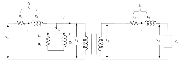
The total equivalent circuit is again given as,
Fig. 11: Total Equivalent Circuit
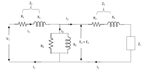
But the above circuit is exact equivalent but harder to solve so, it can be further simplified as,
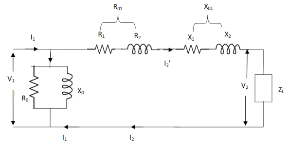
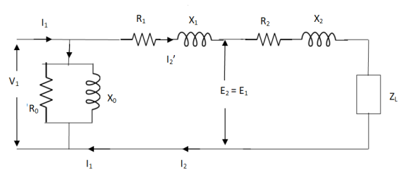
Fig. 12: Simplified Equivalent Circuit
Z = Z1 + Zm || ( Z’2 + Z’L )
= Z1 + Zm(Z’2 + Z’L)/Zm + (Z’2 + Z’L)
Z’2 = R’2 + jX’2
Zm = impedance of exciting circuit
V1 = I1[ Z1 + Zm(Z’2 + Z’L) / Zm + (Z’2 + Z’L) ]
Key takeaway
X0 = E1/I0. R0 = E1/Iw
Z’2 = R’2 + jX’2
V1 = I1[ Z1 + Zm(Z’2 + Z’L) / Zm + (Z’2 + Z’L) ]
1.8.1 Transformer on No Load
When an actual transformer is put on load, we get losses (iron loss) in core and (copper loss) in primary and secondary windings. In NO LOAD (primary current is not purely reactive) the input current has to supply iron loss to core and small amount of copper loss in primary.
The no-load power is W0 = V1 I0 cos Φ0
I0 – no load primary input current
Cos Φ0 – power factor at no-load condition
I0 lags V1 by Φ0 < 900
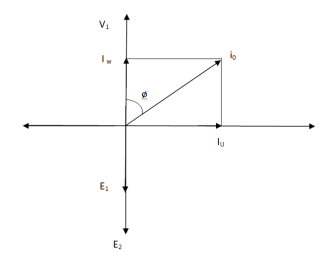
The phasor is shown below.
Fig. 13: Phasor for No-Load Transformer
From above figure we can conclude that I0 has two components Iw(in phase with V1) Iµ in quadrature with V1
Iw = I0ws φ0 (iron loss component)
Iµ = I0 cos φ0 (magnetising component)
I0 = I2µ + I2w
Key takeaway
The no-load primary current I0 is very small as compared to full-load primary current. And hence, no-load cu loss is very small. So, primary input is practically equal to iron loss of transformer.
Q1>. A 2500/200 V transformer draws a no-load primary current of 0.5 A and absorbs 400 W. Find magnetising and loss currents.
Sol: Iron-loss current = No load input(W) / Primary voltage
= 400/2500 = 0.16 A
I20 = I2w + I2µ
Iµ = √I20 – I2w
= √ (0.5)2 – (0.16)2
Iµ = 0.473 A
Q2>. A 1-φ transformer has 1000 turns on primary and 200 on secondary. The no load current is 4 amp at p.f of 0.2 lagging. Find primary current and pf when secondary current is 280 A at pf of 0.6 lagging.
Sol: cos-1 0.6 = 53.130 (sin φ = 0.8)
I2 = 280/-53.130A
Φ = cos-1 0.2 = 78.50
Sin φ = 0.98
I1 = I0 + I’2
I’2 = (I2/K) ( -53.130
K = N1/N2 = 1000/200 = 5
I’2 = 280/5 (-53.130
I’2 = 56(-53.130
I1 = I0 + I’2
= 4(0.20 – j0.98) + 56(0.6 – j0.8)
= 0.80 – j3.92 + 33.6 – j44.8
I1 = 34.4 – j48.72
I1 = 59.64 ( -54.770
I lags supply voltage by 54.770
1.8.2 Transformer On Load
When secondary winding is loaded then the current in it is setup(IQ). The current I2 is in phase with V2 if load is non-inductive it lags if load is inductive & leads if load is capacitive.
Fig. 14: Transformer with Secondary connected to Load
An mmf is set up at secondary and hence φ2 flux is induced which is in opposition to main flux φ due to I0. The flux φ2 weaken φ and hence primary back emf E1 is reduced. An additional primary current I’2 is introduced exactly at instance when I2 is introduced. So, that magnetic effect of I2 is neutralized by I’2.
Φ2 = φ’2
N2 I2 = N1 I’2
I’2 = N2/N1 x I2 = K2 I2
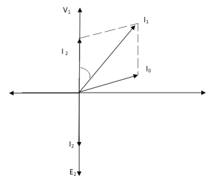
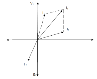
The phasor is shown below,
(a) (b)
Fig. 15: Phasor for Load Transformer
From fig (a) (non – inductive load)
I2 is in phase with E2(=V2)
I’2 is antiphase with but equal in magnitude
I1 is vector sum of I’2 and I0, but lags V1
From fig (b), Inductive load
I2 lags V2
I’2 is not in phase with I2 but equal in magnitude
I1 is vector sum of I’2 & I0 but lags V1
Key takeaway
I’2/I2 = I1/I2 = N2/N1 = K
Q>. A 1- φ transformer with ratio of 440/110-V takes a no-load current of 6 A at 0.3 pf lagging. If secondary supplies 120 A at pf of 0.8 lagging. Find current taken by primary.
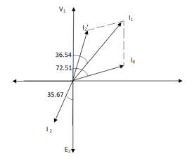
Sol>.
Cos φ2 = 0.8
Φ2 = 36.540
Cos φ0 = 0.3
Φ0 = 72.540
K = V2/V1 = 110/440 = ¼
I’2 = KI2 = 120 x ¼ = 30 A
I0 = 6A
Angle between I0 & I’2
= 72.54 – 36.54
= 35.670
From vector diagram,
I1 = √(62 + 302 + 2 x 6 x 30 cos 35.67)
I1 = 35.05 A
As total transformer loss ( loss +Cu loss)
Depends on VA and has no relation with phase angle between voltage and currents. But  loss depends on current and iron loss on voltage; hence, rating is always KVA.
Q. A 10000/ 250 V, 120KVA 1- Transformer 50 h z supply has core loss of 1.2 KW nas F.L
  loss of 1.8 KW . Find (2) KVA load for max efficiency and value of max. Frequency at unity P.F (2) the efficiency at half F.L 0.8 PF lagging?
Solution: (1) load KVA for max efficiency
= F.L KVA *  = 120 *
  =
=
= 97.98 KVA
At  cu loss = Iron loss
Total Loss = 1.2+1.2 = 2.4kw
Output = 97.98*1 = 97.98kw
 =
=  =1.59%
2) cu Loss at half full load =1.8*( )2=0.45 kw
Total loss =1.2+0.45=1.65kw
Half F.L output at 0.8 pf = *0.8= 48 kw
n= = 0.97
1.10.1 Losses in a Transformer
(1) Core or Iron Loss:
This includes both hysteresis loss and eddy current loss. Iron or core loss is found from open circuit test.
Hysteresis Loss(Wh) = nB1.6max f V Watt
Eddy current Loss(We) = P B2max f2 t2 Watt
(2) Copper Loss:
This is due to ohmic resistance of the transformer windings.
Total cu loss = I21 R1 + I22 R2
= I21 R01 + I22 R02
Cu loss α I2
The value of cu loss is found from short-circuit test.
1.10.2 Their variation with Load, Voltage & Frequency on no Load Losses
Effect on losses due to change in frequency and voltage
i) When the frequency is increased/decreased keeping voltage constant
The hysteresis loss is proportional to the frequency. The hysteresis loss should increase with an increase in the frequency; however, the hysteresis loss remains almost unchanged. The reason is that the flux density in the core gets decrease in the same proportion of the increased frequency.
In a similar way, the hysteresis loss should decrease with decrease in frequency, however the hysteresis loss remains almost unchanged because of increased flux density in the core.
The eddy current loss is proportional to the square of the flux density and frequency. With an increase in the frequency the eddy current remains unchanged because the product of B2m f2 remains unchanged as flux is proportional to ratio of V/f. With decrease in frequency the flux density in the core gets increased in the same proportion of frequency decrease and thus the eddy current loss remains unchanged.
Ii) When the voltage is increased/decreased keeping frequency constant
The hysteresis loss is directly proportional to the voltage and flux density. The hysteresis loss increases with increase in voltage. The magnetic flux density is also proportional to the voltage. Thus, the hysteresis loss is proportional to square of voltage if the frequency is kept constant.
Thus,
Hysteresis loss, Wh ∝ V2
Eddy current loss, We ∝ V3
Iii) When the frequency is increased/decreased and voltage is also increased/decreased in the same proportion
If the frequency is increased and voltage is also increased in the same proportion then the flux density in the core remains unchanged and, in this case the hysteresis loss will increase proportionally to the increase of frequency, the eddy current loss will increase in the square proportion of the increased frequency.
Iv) When the frequency is increased/decreased and voltage is also increased/decreased in different proportion
In this situation the eddy current and hysteresis loss will increase or decrease because of the following reasons.
- Increase/decrease of frequency
- Increase/decrease of flux density
Key takeaway
Hysteresis Loss(Wh) = nB1.6max f V Watt
Eddy current Loss(We) = P B2max f2 t2 Watt
Cu loss α I2
1.11.1 Efficiency
Basically, efficiency is defined as
n = output/input
But for transformer there are small amount of losses so the improved way to find efficiency is
n = output/output + losses
n = output/output + cu loss + iron loss
Or n = Input – losses/Input
= 1 – Losses/Input
1.11.2 Condition for maximum efficiency
For n to be maximum dn/dI1 = 0
(Ww) cu loss = I21 R01 or I22 R02
Iron loss = Hysteresis loss + Eddy current loss
= Wn + We = Wi
n = Input – losses/Input
Primary Input = V1I1 Cosφ1
n = V1 I1 Cosφ1 – losses/V1 I1 cos φ1
n = V1 I1 cos φ1 – I21 R01 – Wi / V1I1 cosφ1
= 1 – I1R01/V1cosφ1 – Wi/V1I1cosφ1
Differentiating w.r.t I1 both sides of above equation we have
Dn/dI1 = 0 – R01/V1cosφ1 + Wi/V1I21 Cosφ1
For max value dn/dI1 = 0
R01/V1cosφ1 = Wi/V1I21 cosφ1
Wi = I21 = I21 R01
Hence,
Wi = Wcu
Iron loss = copper loss
The value of output current for maximum efficiency will be
I2 = √Wi/R02
The maximum efficiency can also be given as,
nmax = full load x √ Iron loss / F.L. Cu loss
Or
nmax = R’ x full load KVA x pf / R’ x full load KVA x pf + Wi + Wcu x 100
R’ = ratio of actual to full load KVA
Wi = iron loss (KW)
Wcu = copper loss (KW)
Key takeaway
nmax = R’ x full load KVA x pf / R’ x full load KVA x pf + Wi + Wcu x 100
n = output/output + cu loss + iron loss
Or n = Input – losses/Input
Q1). In a 50 KVA, 2200/200 V, 1-φ transformer, the iron and full-load copper losses are 400 W and 450 W respectively. Calculate n at unity power factor on (i). Full load (ii). Half-full load?
Sol. (i). Total loss = 400 + 450 = 850 W
F.L output at unity power factor = 50 x 1
= 50 KVA
n = 50 / 50 + .850 = 50/50.850 = 0.98 = 98%
(ii). Half full load, unity pf
= 50 KVA/2 = 25 KVA
Cu loss = 400 x (1/2)2 = 100 W
Iron loss is same = 450 W
Total loss = 100 + 450 = 550 W
n = 25/25 + 0.55 = 25/25.55 = 0.978 = 97.8 %
Q>. A 40 KVA 440/220 V, 1- φ, 50 Hz transformer has iron loss of 300 W. The cu loss is found to be 100 W when delivering half full-load current. Determine (i) n when delivering full load current at 0.8 lagging pf (ii) the percentage of full-load when the efficiency will be max.
Sol. Full load efficiency at 0.8 pf
= 40 x 0.8/(40 x 0.8) + losses
Full load cu loss = (440/220)2 x 100
= 400 W
Iron loss = 400 + 300
= 700 W
n = 40 x 0.8/(40 x 0.8) + 0.7 = 97.8 %
(ii). KVA for maximum / F.L KVA = √ iron loss / F.L cu loss
= √300/400 = 0.866
Usually transformer efficiency is given as
n=
But there are few transformers in which their primary winding is energized for whole day. And their secondary supplier no load. So, the core loss occurs for whole day and loss occurs only when transformer is loaded. now n becomes.
 =
=
Q. Find all day efficiency of 500KVA distribution transformer whose loss and iron loss are 5.5 kW and 4.5 kW. During day it is loosed as
No of hours | Loaded in kw | Power factor |
6 | 400 | 0.8 |
10 | 300 | 0.75 |
4 | 100 | 0.8 |
4 | 0 | - |
|
|
|
Solution:  loss at full load of 500 KVA =5.5KW
Load at 400kw 0.8 pf =  =500KVA
Load at 300kw 0.75 pf =  =400KVA
Load loss at 400 KVA =0.8= =125KVA
 Loss at 400KVA =5.5 *
  2
2
=3.52 KW
 . Loss at 125KVA=5.5*(
 )2
)2
=0.345KW
Total  loss in 24 hr = (6*5.5) + (10*3.52) + (4*0.345) + 0
= 66.38kwh
Iron loss in 24hr =24*4.5 =108 kwh
Total transformer loss =66.38+108
=174.38 kwh
Transformer output 24hr= (6*400) + (10*300)
= (4*100)
=5800 kwh
 =
=
=  =0.97
=0.97
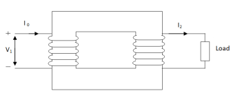
1.13.1 Auto Transformer
It is a transformer in which only one winding is common it both primary and secondary because it has one windy it uses loss copper and is cheaper.
It can be step -up and step-down auto transformer. The circuit for both is shown below.
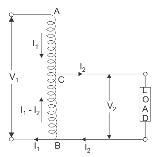
Fig. 16: Auto Transformer
AB-Primary winding
BC- Secondary windings
Negating iron loss and no-load current-
 =
= =
= =K
=K
The current in CB( ) is vector difference (
 -
- )
)  >
>
Key takeaway
An auto transformer when compared to as ordinary 2- winding transformer having same output, given higher efficiency and is smaller in size with superior voltage regulation.
1.13.2 Rating and Application
Rating
As total transformer loss ( loss +Cu loss)
Depends on VA and has no relation with phase angle between voltage and currents. But  loss depends on current and iron loss on voltage; hence, rating is always KVA.
Applications
The applications of an auto transformer include:
- Compensating voltage drops by boosting supply voltage in distribution systems.
- Auto transformers with a number of tapping are used for starting induction and synchronous motors.
- Auto transformer is used as variac in laboratory or where continuous variable over broad ranges are required.
Key takeaway
Rating is always KVA
FOR AUTO TRANSFORMER:
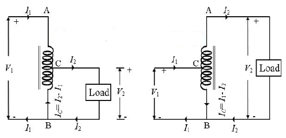
Fig. 17: (a) Set-Up Auto-Transformer Fig. 17: (b) Step-down Auto-Transformer
From above fig 17 (a)& (b)
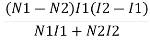
Weight of copper in AC  (N1-N2)I1
Weight of copper in BC (N2(I2-I1)
Total weight of copper  (N1-N2) I1+N2(I2-I1)
  auto transformer
For 2- winding transformer:
Weight of  on primary
  N1I1
N1I1
Weight of  on primary
  N2I2
N2I2
Total weight of  N1I1+N2I2

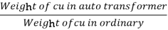 =
=
=  = 1-
= 1- =1-k
=1-k
 = K ,
= K ,  =
=
Weight  in auto transformer =(1-k)*(weight of
  in ordinary transformer)
Saving = Wo-Wa
= W0-(1-k)W0
Saving = Kwo
Key takeaway
Power transformer inductively =(1-k) input hence, saving will increase at K approaches unity.
Q. An auto transformer suppliers load of 4KW at 100v at unity pf. IF the applied primary voltage is 220v. Calculating power transferred to load (a) Inductively (b) conductively.
Sol: Power transferred inductively = Input(1-k)
Power transferred conductively = K* Input
K=  =
=
Input= Output =4KW
Inductively transferred power =4( )
)
=3.82KW
Conductively transferred power =  *4
*4
= 0.182 kw
References
[1] Edward Hughes “Electrical Technology”, ELBS, Pearson Education.
[2] Ashfaq Husain, “Electrical Machines”, Dhanpat Rai & Sons.
[3] S. K. Bhattacharya, “Electrical Machine”, Tata McGraw Hill publishing Co. Ltd, 2nd Edition.
[4] Nagrath & Kothari, “Electrical Machines”, Tata McGraw Hill.
[5] Bhag S Guru, Husein R. Hiziroglu, “Electrical Machines”, Oxford University Press.
[6] K Krishna Reddy, “Electrical Machines- I and II”, SCITECH Publications (India) Pvt. Ltd. Chennai.


