Unit 6
Other sources and grid connection
Biomass is an organic matter from plant, animals and microorganisms grown on land and water and their derivatives. The energy obtained from biomass is called biomass energy.
Biomass resources
1) Concentrated wastes
A) Municipal solid
B) Sewage wood product
C) Industrial waste
D) Manure at large lots
2) Dispersed waste residue
A) Crop residue
B) Logging residue
C) Disposed manure
3) Harvested biomass
A) Standing biomass
B) Biomass energy plantation
The gas turbines cannot run directly on biomass fuels since the resulting combustion products would damage the turbine blades, so an intermediate step would have to be introduced. By gasifying the fuel first and then cleaning the gas before combustion, it would be possible to use biomass with gas turbines.
Biomass can be converted into biogas by an aerobic decomposition of organic waste by suitable bacteria. It mainly consists of (55-65)%  , (30-40%)
  & reminder other gases. It has a calorific value of 21000 to 23000KJ/Kg. Biogas can be used in S.I. Engines coupled to a generator to produce electricity.
Method to obtain energy from biomass
1) Combustion
2) Anaerobic digestion
3) Pyrolysis
4) Hydrolysis and ethanol fermentation
5) Gasifier
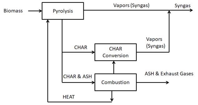
- Biomass gasification process-
A two-step process for gasifying biomass fuels is illustrated in Figure. In the first step, the raw biomass fuel is heated, causing it to undergo a process called pyrolysis in which the volatile components of the biomass are vaporized. As the fuel is heated, moisture is first driven off; then at a temperature of about 400 C the biomass begins to break down, yielding a product gas, or syngas, consisting mostly of hydrogen (H2), carbon monoxide (CO), methane (CH4), carbon dioxide (CO2), and nitrogen (N2) as well as tar. The solid byproducts of pyrolysis are char (fixed carbon) and ash. In the second step, char heated to about 700
 C reacts with oxygen, steam, and hydrogen to provide additional syngas. The heat needed to drive both steps comes from the combustion of some of the char.
The relative percentages of each gas vary considerably, depending on the technology used in the gasifier, and so does the heating value of the mix.
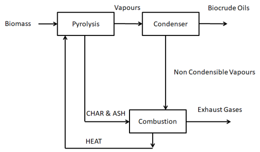
b. Biomass pyrolysis used to create liquid biocrude oil-
Pyrolysis reactions can also be used to convert biomass to liquid, as diagrammed in Figure. Different temperatures and reaction rates produce energyrich vapors that can be condensed into a liquid “biocrude” oil with a heating value about 60% that of diesel fuel.
c. Anaerobic digestion-
Another technology for converting biomass to energy is based on the anaerobic (without oxygen) decomposition of organic materials by microorganisms to produce a biogas consisting primarily of methane and carbon dioxide. The biochemical reactions taking place are extremely complex, but in simplified terms they can be summarized as
CnHaObNcSd + H2O + bacteria → CH4 + CO2 + NH3 + H2S + new cells
The domestic waste in the cities is usually sent to landfill sites located for away from the centre of the city. Large cities like Delhi, Bombay have large amount of waste and increasing waste disposal problems.
The emerging solution is to produce used thermal and electrical energy by waste to energy plant located in the heart of city.
Serve the following function
1) Supplier of economical disposal of urban waste.
2) Supply of electrical and thermal energy to the consumers in the city.
3) Environmental protection from urban waste.
Biomass energy=> thermal energy=> electrical energy
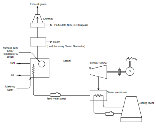
Figure waste to energy plant for municipal solid waste
Geothermal energy is primary heat energy from earth own interior. Geothermal energy from the earth interior is almost in exhaustible as solar or wind energy so long as its sources are actively sought and economically tapped.
● As we traveled down earth surface radially there exist a temperature gradient of 0.03°C per metre. Thus a 30°c increases in temperature can be obtained per kilometre depth from the earth crust.
● Generally available deep inside the earth at a depth of more than 60 km. Hence not possible to extract.
● In a few location in the world comedy posit are at depths of 300 to 3000 m. Such as location are called geothermal fields.
● most of the world volcanic activities and geothermal site are located in circum Pacific belt known as rim of Fire. It start from New Zealand, Philippines, Japan, North America Mexico etc.
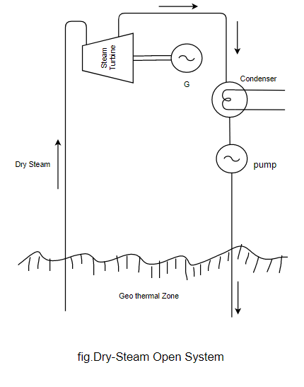
Dry steam open system or vapour dominated
The vapour dominated reservoir produce dry saturated steam of pressure above atmosphere and at high temperature about 350°c.
● Steam extracted from the well is cleaned in centrifugal separator which removes solid matters.
● The cleaned steam is then supplied directly into the steam turbine. The exhaust steam from steam turbine is wet steam (i.e. mixture of water and steam) which passes through the condenser. The condenser condensers wet steam into water.
● This system used in Landerallo (Italy) & Geyser (USA).
Binary cycle system
The binary cycle concept isolates the steam turbine from corrosive or non corrosive material or to accommodate higher concentration of non condensable gases.
This is basically a Rankine cycle with an organic working fluid.
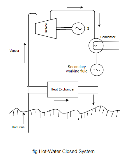
About 50% of hydro thermal water is in the temperature range 153°C to 205°C. In this system heat exchanger is used to transfer a fraction of the brine enthalpy to vaporize the secondary working fluid. Expansion through a turbine to a lower pressure is fixed by the heat rejection temperature which provide the mean for power generation.
● In this system there are no problems of corrosion.
● This system was first installed in the Soviet Union 1967 -680KW
Ocean energy:-
The ocean, large lakes and bays are use reserve wires useful and renewable energy source. World total estimated Ocean energy reserve via our about 
Due to rapidly depleting fossil fuel sources the ocean energy is likely to gain a significant importance during coming decades.
Ocean energy sources
A) Tidal energy
It refers the hydro energy in Ocean tide Ocean tides occurs due to gravitational attractive forces from sun and moon. The level of ocean water rises periodically during high tides and drops during low tide.
The difference in head of water during height tide and low tide is used for rotating hydro turbine generator unit installed within barrages to obtain electrical energy.
The periodic rise and fall of the water level of sea which are carried by the action of the sun and moon on water of the earth is called tide.
Power generation from tidal plant
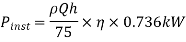
h=available height at the instant, m
 for sea water
 =Overall efficiency
Q =Average discharge
Site requirement:-
1) The site should have a large tidal range.
2) Capable of staring a large quantity of water for energy production.
3) Site should be located in an estuary or creek.
4) It should be near to load centre.
Tidal power plant
A tidal power plant consists of the following component
1) Dam or dyke (low wall)
2) Sluice ways
3) Power house
Single basin tidal plants
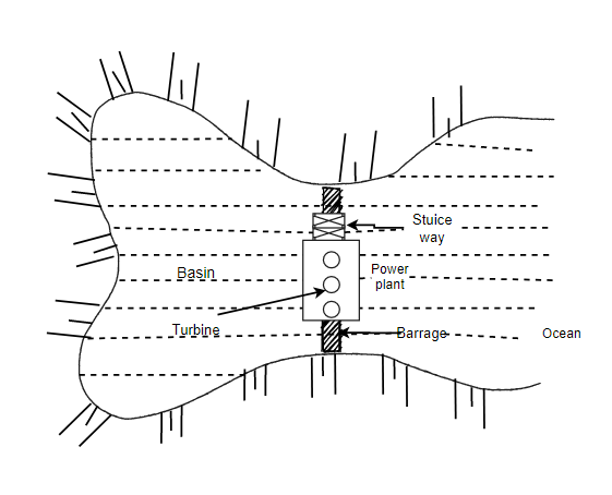
● A barrage separates the basin from the sea.
● A sluice where is opened during high tide to fill the basin.
● The turbine generators units are mounted with the ducts inside the barrage.
● Power house is built on the barrage.
Fuel cell:-
A fuel cell is an electrochemical device in which the chemical energy of a conventional field is converted directly and efficiently into low voltage, direct current electrical energy.
● Fuel cell system generally operates on pure hydrogen and air to produce electricity.
● The essential difference between the primary/secondary cell & fuel cell is of continuous energy input and output of fuel cell. A fuel cell system requires continuous supply of fuel and a oxidizer and generate DC electric power continuously.
Advantages:-
1) Conversion efficiencies are high-55%
2) Require little attention and less maintenance
3) Fuel cell is odorless and does not make noise.
4) A little time is needed to go into operation.
5) Space requirement considerably less.
6) Simple and safe
7) Pollution free
8) No cooling water needed
9) Capacity can be increased as demand grows
10) Long life
Disadvantages
1) High initial cost
2) Low service life
3) Problems for refilling in vehicles
Applications
1) Domestic use
2) Automotive vehicles
3) Central power station
4) Defense application
5) Space project
● Fuel cell primary suited for low voltage and high current application.
Component and working theory of fuel cell
1) Anode
2) Cathode
3) Electrolyte
4) Container
5) Separator
6) Sealing
7) Fuel supply
8) Oxidizer

At negative 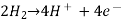
At positive 
The fuel gas diffuses through the anode and is oxidized, thus releasing electrons to the external circuit.
● The oxidizer diffuses through the cathode and is reduced by the electrons that have come from the anode by way of the external circuit.
● the fuel cell is a device that keep the fuel molecules from mixing with the oxidizer molecule permitting however, the transfer of electrons bimetallic path that may contain load.
● Of the available fuels, hydrogen has so far given the most promising results, although cell consuming coal, oil or natural gas would be economically much more useful for large scale application.
Some possible reaction
Hydrogen/oxygen 1.23V 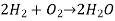
Hydrazine 1.56V 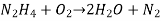
Carbon (coal) 1.02V 
Methane 1.05V 
Electrode-Nickel
Electrolyte-Sulphuric acid or potassium hydroxide
Catalyst-platinum
Which break the fuel compound into more reactive atoms.
Fuel cell storage requirement electrolyte
1) It should be conductive to ions.
2) It should be electrically non-conductive.
3) Ions should be free to move through the electrolyte.
4) The composition of electrolyte should not get changed during operation.
Electrode
1) It should be electrically conductive.
2) It should not react with electrolyte to prevent corrosion.
3) It should able to withstand high temperature.
4) It should also act as catalyst to convert hydrogen and oxygen molecules into their ions.
Selection criteria:-
1) It should have high energy conversion efficiency.
2) It should be flexible to choose any fuel.
3) Cost
4) Availability of fuel and its heat.
5) Size/volume of cell
6) Transportability
Fuel cell power plant
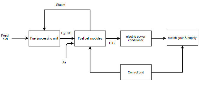
● The primary fossil fuels are used to generate electrical energy in fuel cell power plant.
● The fossil fuel is supplied to the fuel processing unit, where fuel is purified and then supply to fuel cell module.
● The fuel cell module converts fuel energy electrochemically into DC power.
● A number of fuel cell are stacked to form a module and several module are interconnected to form a power producing unit
● The power conditioning unit converts DC output to AC output using inverter and the standard rated supply being
● Module of size 200-250kW are commonly available.
When the grid isn’t nearby, electricity suddenly becomes much more valuable and the extra cost and complexity of a totally self-sufficient, stand-alone power system can provide enormous benefit.
Figure suggests a quite general system that includes a generator backup as well as the possibility for some loads to be served directly with more-efficient dc and others with ac.
A combination charger–inverter is shown, which has the capability to convert ac to dc or vice versa. As a charger, it converts ac from the generator into dc to charge the batteries; as an inverter, it converts dc from the batteries into ac needed by the load. The charger–inverter unit may include an automatic transfer switch that allows the generator to supply ac loads directly whenever it is running.
Off-grid systems must be designed with great care to assure satisfactory performance. Users must be willing to check and maintain batteries, they must be willing to adjust their energy demands as weather and battery charge vary, they may have to fuel and fix a noisy generator, and they must take responsibility for the safe operation of the system. The reward is electricity that is truly valued.
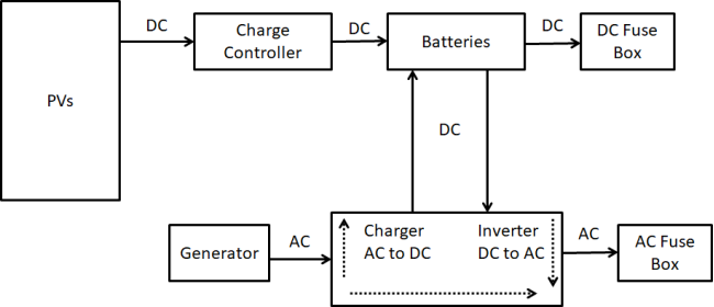
Figure-Off grid Stand alone system
a. Hybrid stand-alone system-
Hybrid systems include more than one sources of power. It is always desirable to design a system with additional source of power.
The most common type of hybrid system contains a gas or diesel powered engine generator.
Sometimes the PV or Wind system is used to provide the power demand, which adds the more advantages to the systems. These systems consist of the following:
- Solar panels mounted on the roof or in open spaces. Photovoltaic modules produce direct current (DC) electrical power.
- Batteries to store DC energy generated by the solar panels.
- Charge controller to prevent overcharging the battery.
- Specially designed inverter to transform the PV generated DC electricity to the grid electricity (which is of AC) at the grid voltage.
The following diagram shows PV system powering AC loads. This system is connected to utility power supply & diesel generator and having battery storage for backup.
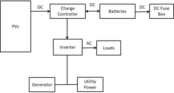
Figure-Hybrid Stand alone system
b. Grid connected stand alone system-
A grid connected photovoltaic system will be interacted with utility grid. The main advantage of this system is that power can be drawn from the utility grid and when power is not available from grid, PV system can supplement that power. These grid connected systems are designed with battery or without battery storage. These systems consist of the following:
- Solar panels mounted on the roof or in open spaces. Photovoltaic modules produce direct current (DC) electrical power.
- Batteries to store DC energy generated by the solar panels.
- Charge controller to prevent overcharging the battery.
- Specially designed inverter to transform the PV generated DC electricity to the grid electricity (which is of AC) at the grid voltage.
The following diagram shows PV system powering AC loads. This system is connected to utility power supply and having battery storage for backup.
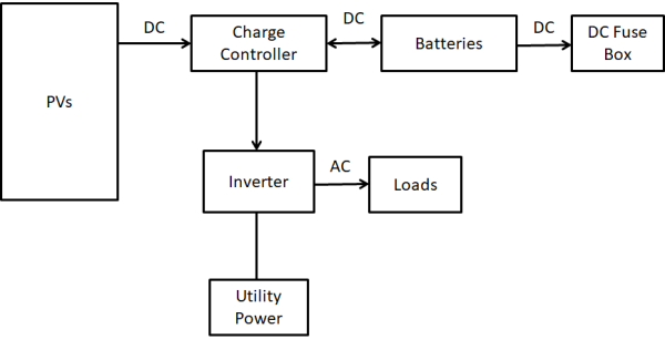
Figure-Grid Connected Stand alone system
Reference Books:
- [R1] Arora and Domkundwar, “A Course in Power Plant Engineering”, Dhapat Rai Publication.
- [R2] Dr. S. P. Sukhatme, “Solar Energy”, Tata McGraw Hill Publication.
- [R3] Mukund Patel, “Wind and Solar Power Plants”, CRC Press.
- [R4] Gilbert Masters John, “Renewable Energy”, Wiley and sons’ publications.
- [R5] Robert Foster, Majid Ghassemi, Alma Cota “Solar Energy” CRC Press


