Unit 3
Hydroelectric power plant
A generating station which utilizes the potential energy of the water at high level for the generation of electricity is known as HPS.
Basic principle of HPS:-
PE->KE->ME->EE
1) We know that water is stored in a dam by using rainwater. This stored water contains potential energy due to height or head of the dam.
2) Hence this water flows toward turbine at the time the movement causes kinetic energy.
3) This kinetic energy is converted to mechanical energy.
4) the turbine or prime mover is mechanically coupled with the generator whenever turbine starts to rotate with the help of high pressure water automatically generator starts to rotate.
5) And electrical energy is produced.
The factors that should be considered.
For selecting the side of HP’s:-
1) Quantity of water required:-
The HPS totally runs on water so ample of water is should be continuously available throughout the year.
2) Hilly area required:-
For storage of ample quantity of water on both side of the dam hilly area of strong mountains are required for storage.
3) Civil work:-
It should have a strong foundation and the cost of foundation should be as low as possible.
4) Large catchment area :-
Large catchment area is required so that the water in it should never for below the minimum level.
5) Transportation facility:-
For the workers and civil material required, better transportation facility should be their.
6) Near to load centre:-
To reduce the cost of transmission and distribution the plant should be located near the load centre.
7) Availability of material:-
At the time of erecting the dam and powerhouse, a huge amount of civil material should be easily available without storage.
8) Area free from earthquake:-
Area should be free from earthquake because flood may occur.
9) Accommodation facility:-
For operational and maintenance staff better facility of accommodation should be provided at the reasonable rate.
10) Future expansion:-
For increasing per megawatt capacity of plant, the space should be available for the future expansion.
Basic definition
The system which is related to water is called hydrology. It is related to head of water, flow of quantity of water, mass of water.
The above data is useful to decide the installed capacity of HPS.
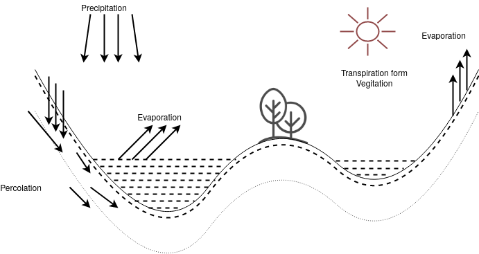
Surface runoff:-
It is the portion of precipitation which makes its way towards stream, lakes or oceans, runoff can be possible when the rate of precipitation exceeds the rate at which water infiltrates in the soil.
R=P-E
R=runoff water
P=precipitation
E=evaporation
Evaporation:-
It is a transfer of water from liquid to vapour state.
Precipitation:-
It includes all types of water falls from atmosphere to earth surface.
1) Liquid precipitation (rain fall)
2) Solid precipitation (snow)
Significance of precipitation on the capacity of power plant
1) The quantity of water is available to store in dam
2) To know the head
3) To know the quantity of water available per second order per hour.
4) It helps to determine the power in KW
5) To know the installed capacity of power plant
HPS are classified as follow
a) Based on availability of head
● Low head plants.
● Medium head plants
● High head plants
b) Based on the nature of load
● Base load plants
● Peak load plants
c) Based on quantity of water available
● Run of river plants without Pondage
● Storage type plants
● Pumped storage peak load plants
● Mini and micro hydro plants
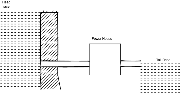
Low head hydroelectric plants
● The low head plants have the water head below 30 meters
● A low power plant store water by construction of dam across the river or lake.
● The powerhouse is installed on the downstream side
● The villages which regulating gates are provided to flow offs the excess water in the river or lake
● In low head hydroelectric power plant frands , propeller or plant types of hydraulic turbine are used
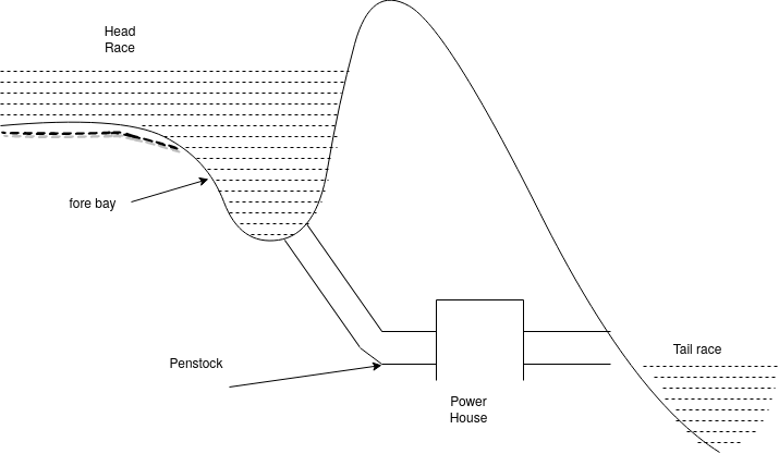
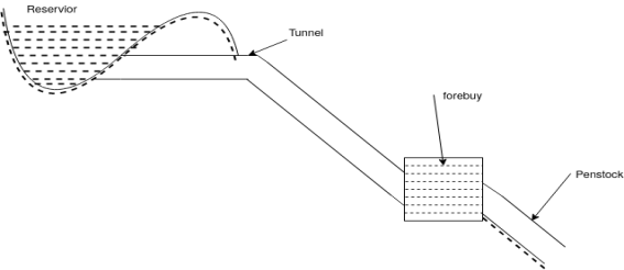
Medium head hps
● Medium head plants have the water head in between 30 to 100 meters.
● The water is lead to the turbines from fore bay by the penstocks (this maybe steel pipes)
● Forebay also shares the rejected water when the lord on the turbine decreases.
● Francis turbines are used for this plant.
High head power plant
● When the power plant have the water head more than 100 metres and up to 2000 then it is called as high head power plants.
● The civil works include the surge tank (the function of surge tank) is to fulfill the requirement of water when fluctuation is load occurs.
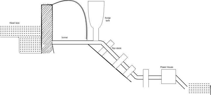
● The plant uses transistor been when the water is lead up to 300m and the plant uses pelton wheel when the water head is more than 300 m.
Base load plants
● The unvaring load which occurs almost the whole day on the station is called as base load
● From figure it is clear that 20m of the load to be supplied by the station at all times of the day and night that is throughout 24 hours.
● So 20m is the best load of the station it is constant in nature
● The base load plant has largest capacity and load factor.
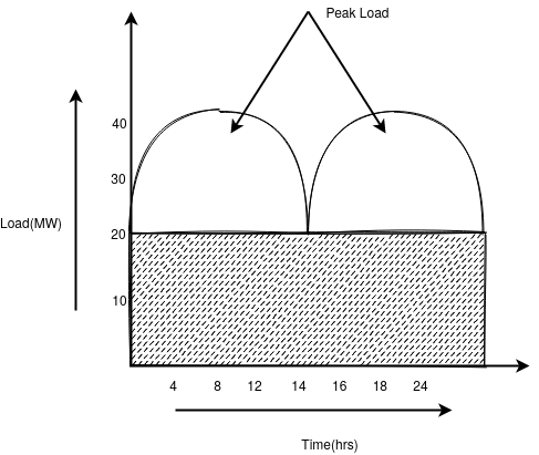
Peak load plant
● The various speed demands of the load over and above the base load on the station is gold as peak load
● Run off river plants with the pondage can be used as peak load
Run off river plants without pondage
● In this type of HP is the availability of water from river or lake is not stored in Pond.
● whenever the water is available from the river or lake it is directly used to run the water turbine
● The capacity of such plants depends upon the rate of flows of water.
● Such plant may run during rainy season
Run off river plant with pondage
● Run off river plants without pondage have limitations to overcome this drawback in this type of HPS the available water from river or lake is stored in the pond.
● Due to the storage of water in a pond it is useful to run the plants during off Peak and peak period.
● The capacity of such HPS depends on the size of pond .
Storage type plants (reserve air plants)
● This type of HPS is different from the above mentioned plant
● In this type reserve air is provided this reserve near is contains ample quantity of water during rainy season and useful throughout the year
● Such type of plant have better capacity and can be used as base load plants
The pumped storage plant
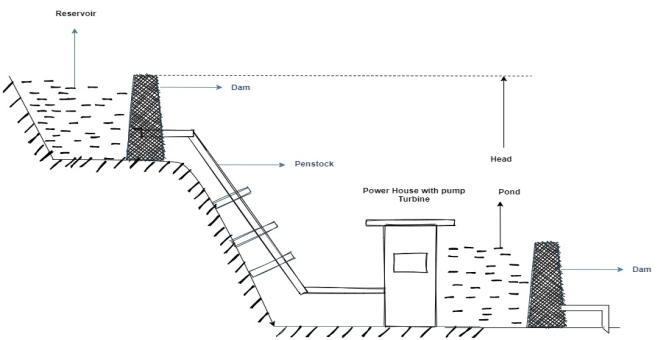
● This type of power plant is useful where the availability of water for power generation is not sufficient.
● Generally there are two poles one is in the head race level and other is in the tail race level.
● This stone water from the head respond is useful for electrical power generation.
● When the water flows towards turbine it starts the rotate .
● The discharged water from turbine is stored in trail race pond.
● During off-peak period the water from the tail race pond is pumped to the head race pond again with the help of motors.
● The cycle is continuously repeated hence it is called as pump storage hydroelectric power plants
● In this plants very little water is required for its open as compared to other plants
(The additional water is only required in case see page and evaporation from the storage reserve air)
Mini and micro hydal power plant
● to overcome the present power crisis up to certain extent in a country mini and micro hydro power plant can be built
● Mini power plant work in the range of 5 to 20 m head
● Micro hydro plant work under the head less than 5 M
● Since the capital k cost per k/w is high for such plants such low head mini hydro plants have not been explode except in the state of UP HP and Arunachal Pradesh.
● The estimate suggests that the potential of these many plants all over the country may be as much as 20000 KW.
● Such plants of lease capacity can be built in a very short time
● Mini hydal plants use special type of turbine called as bulb type turbine.
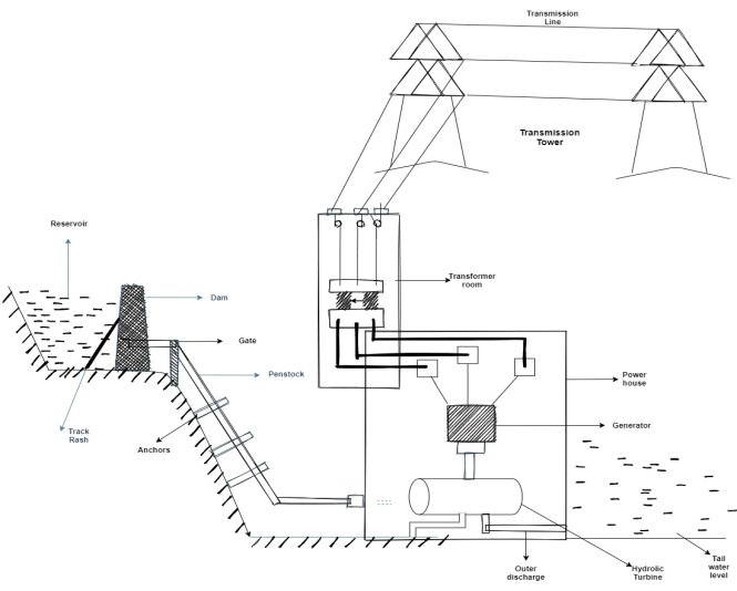
The thief requirement for hydroelectric power plant is the availability of water in huge quantity at sufficient head and this requirement can be met by constructing a dam across a river or lake. The schematic arrangement of a typical hydroelectric power plant is shown in figure.
An artificial storage reservoir is formed by constructing a dam across the river or lake and a pressure tunnel is taken off from the reservoir to the wall house at the start of the penstock.
The valve house contains main sluice valves for controlling water flow to the power station and automatic isolating valves for cutting off water supply in case the penstock bursts.
A Surge tank is also provided just before the house for better regulation of water pressure in the system.
From the reservoir the water is carried to valve house through pressure tunnel and from valve house to the water turbine through pipes of large diameter made of steel for reinforced concrete called the penstock.
The water turbine converts hydraulic energy into mechanical energy and the alternator coupled to the water turbine converts mechanical energy into electrical energy.
Function of different components used in HPS
Catchment area
● By collecting the rainwater to surrounding heavily area it is stored in one place this is known as catchment area.
● More is the catchment area larger will be storage
Reservoir
● The function of reserve air is to store water near dam
● The water is useful to drive the water turbine
● The deserve air is useful to provide a head of stored water
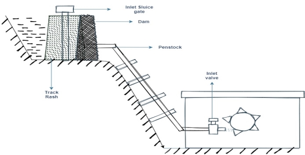
Track rash
● It is used in HPS to filter the water before it flows towards turbine
● The unwanted impurities like fish, plastic present in the stored water should be avoided to flow towards turbine
Head race level
● The water surface in the reserve year up to the dam is called as head race level
Turbine
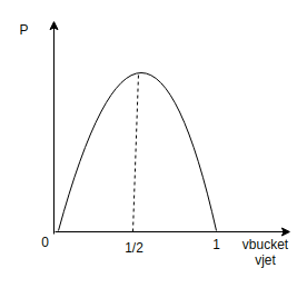
Pelton wheel turbine (impulse)
V bucket=
P =f impulse ×v bucket
Types of turbines:-Turbines in the HPS acts as prime mover of the generator the classification is as follow.
a) According to type of flow of water
● Axis along the shaft of machine.
● Axis along the radius
● Axis along the tangential direction
b) According to action of fluid
● Impulse
● Reaction
Impulse:-
● Such type of turbines are used for high heads
● In impulse turbine the entire press sure of water is converted to kinetic energy in nozzle and the velocity of jet drives the wheel
● Eg:- Pelton wheel
Reaction turbine:-
● They are used for low and medium heads
● in the reaction turbine water enters the runner partly with pressure energy and velocity
● Reaction turbines are classified into two types
i) Francis turbine
Ii) Caplan turbine
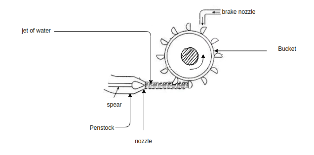
Palton wheel turbine:-
● Pelton wheel is impulse type turbine
● It is used at high head (90-1100m)
● It is specific speed is 10 to 40 m
● It consists of the rotor equipped with elliptical pockets along the whole peripheri
● Tiles and wheel turbine consists of runner, bucket, nozzle, needle value and shaft.
● The buckets are made up of stainless steel cast iron and bronze material.
● In this type of turbines one or two jets are used to force the water through buckets
● The nozzle are used to increase the pressure of water flow towards turbine.
● The short is useful for mechanical coupling with generator
● The direction of flow of water is tangent.
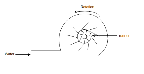
Francis turbine:-
● It is a reaction type of turbine is mostly used for medium head water (14 to 300m)
● The specific speed of Francis turbine is to 250 MP.
● It consist of outer and inner rings plates will accept the outer ring consists of stationary guide leaves which are fixed to the casing.
● the inner ring consists of rotating blades the water flows in Francis turbine in radial direction.
● Sometime draft tube is used for discharge of water directly into trail race.
● Francis turbine is of both horizontal and vertical type horizontal turbines are used for highest speed and vertical are used for higher capacity.
● The diameter and weight of the turbine is less the blades in both the direction according to flow of water.
● At highest speed it is very efficient.
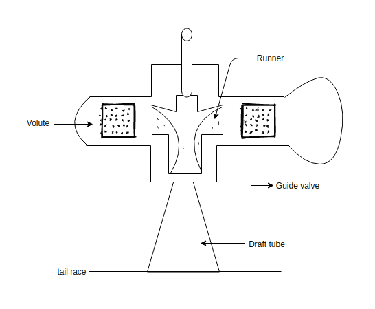
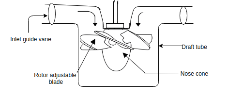
● The Kaplan turbine is a reaction type of turbine and it is used for low head 3 to 30m.
● Specific speed of Kaplan turbine is 550 to830 RPM Kaplan turbine consists of runner blades, casing, guide blades, guide wheels, draft tube and shaft.
● It consists of 3 to 6 plates.
● In the Kaplan turbine water strikes in axial direction.
● The guide vanes are used to control the speed of water
● This type of turbines have higher efficiency at all loads
● It is used for low health but to run this turbine the quantity of water required is large.
● Draft tube is useful to discharge the water to trail race level.
● The shaft is useful for mechanical coupling between turbine and generator.
Governing and hydraulic turbines
● The regulation of the speed of turbine within prescribed limit according to the variation of load on the turbine is called as governing of the turbine.
The function of the turbine governors are
● It should control the speed of turbine when load fluctuates at synchronous speed of the generator.
● It helps to start and shutdown the turbine unit by opening and closing the nozzles of the pelton wheel and gales in case of reaction turbine.
Governing mechanism:-
● The rate of discharge of the water in the turbine is adjusted by changing the floor area of the nozzle in order to meet or fulfill the changing load requirements with the help of governor mechanism.
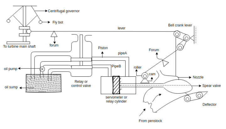
Consider a case,
When a load on the generator increases then the speed of the generator and that of turbine will decrease.
● As the governor is driven by a turbine shaft its speed will also decrease as a result the fly ball of the governor will move in words because the centrifugal force on the Bola decreases.
● Show the sleeve of the governor will move in the downward direction.
● The downward motion of the sleeve will be transferred to the main lever through its fulcrum.
● Hence piston rod of the relay valve will move upward and simultaneous will bell and crank lever will also move upward.
● Due to the upward motion of piston rod of control e valve, the pressurized oil flows through pipe A through the railway cylinder and exerts a force on face. The piston of servo motor.
● It moves the piston to the left hence the square rod with its valve will also move towards left direction.
● It will increase the nozzle area and the rate of flow of water to the turbine increases.
● Hence input to the turbine and ultimately its speed increases.
● When piston of the servo motor moves towards left, the oil present in the cylinder towards face B is transferred to the oil. Sum p through pipe B and relay valve.
● When the speed of the turbine finally adjusted to the normal speed the system returns to the original position.
● Exactly opposite will be the case when lord on the generator.
Comparison between Impulse and Reaction Turbine
Sr. No. | Impulse turbine | Reaction turbine |
1) | It works on the principle of impulse | It works on principle of impulse as well as reaction |
2) | Water from the nozzles comes in the form of jet which impinges on the bucket of runner. | Water is guided by the guide blades to flow over the moving vanes.
|
3) | Flow of water over the runner is at constant atmospheric pressure | The flow of water over the runner is under the pressure which slowly decreases from inlet to outlet |
4) | All the available head is first converted into kinetic energy in nozzle | Only a part of available head is converted into kinetic energy in the guide vanes |
5) | Possible to regulate the flow of water without loss. | It is not possible to regulate the flow of water without loss. |
6) | Suitable for high heads. | Suitable for medium or low heads. |
7) | The work is done due to change in kinetic energy of jet. | Most of the work is done due to the change in pressure head and a very small work is done due to the change in kinetic energy. |
Comparison between Francis and Kaplan Turbine
Sr. No. | Francis | Kaplan |
1) | Water enters the runner radially | Water enters the runner axially. |
2) | Only guide pens are adjustable | Guide vanes and moving vanes are both adjustable |
3) | Frictional resistance is high | Frictional resistance is less due to less number of vanes . |
4) | Number of blades are 16 to 24 is general | Number of blades are generally 3 to 4 |
5) | It is big in size | It is compact in size |
6) | High efficiency is obtained only at high loads | High efficiency is obtained even at part loads |
7) | Specific speed range 50 to 250 | Specific speed range 250 to 850 |
The selection of a water turbine depends upon our factors such as working head, available discharge, speed, output and nature of load.
The effective head under which the turbine is to operate give the first Guide to the selection of the type of turbine.
For very high head i.e. 500 metres and above, Pelton turbine is usually employed.
Reaction turbines are not suitable for such type heads as due to high velocity of water, there will be a rapid wear and friction losses.
For medium heads that is about 30 metres and below 500, Francis turbine is usually adopted but impulse turbine may also be adopted even at the expense of efficiency.
For low heads i.e. below 70 metres, popular type of turbine is used.
In case of considerable variation in heads and load Kaplan turbine gives improved efficiency as compared to to the fixed blade propeller turbine.
Even for the same head to different types of turbines may be employed. for example for a head of 200 either of the pelton or Francis turbine can be used.
It is a general practice to select a runner of higher specific speed.
For a larger output but at low head, a runner of highest specific speed is used to keep the size of the turbo alternator and power house smaller and economical.
● It is used to store the water
● It provide suitable head to the stored water.
● This stored water is used throughout year to run HPS
● Dam is made up of cement concrete and sand material.
● When heavy rainfall occurs the door of dam others to follow the water.
● Dam is one of the main structure in the HPS it is a thick wall made of RCC ,earth ,and stone masonary
● To increase the water level for storage of high head
● It is usually built across a river
● The factor that should be considered for selection of site for dam
a) Material for construction of dam should be easily available and accessible for site.
b) Soil bearing capacity should be high
c) Site should have transformation and communication facility
d) It should be located at the neck of river.
e) It should be away from earthquake zone.
f) It should be economical to construct
g) Good catchment area should be available on upstream side.
Classification of dam
Field dams.
● Earth dam
● Backfield dam
Masonry dams
● Gravity dam
● Buttress dam
● Arch dams.
Timber dams.
Gravity dam:-
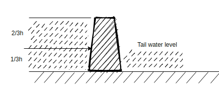
● Gravity dance are constructed by RCC or stone masonry.
● The water thrust is resisted by gravity
● the cross section of solid gravity dam is shown in the figure because of its high weight it requires a solid rocky Foundation
Advantages
● Such type of dam can be constructed faster with high quality of construction
Buttress dam
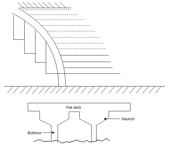
● Buttress dam has flat deck which is lead on mounted on supporting structure called as buttress
● It is also called as hollow gravity type dam
Advantage
● This dams are cheaper as it require much less concrete
● Weight of the water P on the deck is transmitted to buttress as thrust .
Arch dams
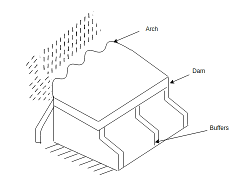
● Such type of dams are not used generally because construction of such dams required a very narrow valley with sleep slops solid rocks.
● So that it can resist large thrust of water.
Earth dam
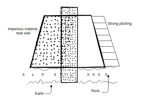
● Such dams are constructed for the small hydro plant up to 70 M height.
● This construction is made of the earth filled with wide base.
● The cross-section of the earth dam is shown in the figure as such type of dam required a large volume of earth material such material should be available near the side of dam construction.
● The side slope of the dam are done by stone pitching.
Advantages
● These are cheap in construction as compare to masonry dams.
● It has long life is protected from corrosion.
Disadvantage
● More seepage losses
● It may be subjected to a serious damage from erosion by water.
● It is not suitable for spillway structures
Rockfield
● It is constructed from loose rock of all sizes
● It has trapezoidal shape with wide base with water tight section to reduce seepages.
● It is suitable for mountainous region where all sizes of rocks are easily available
It is provided to controlling flow of water from reservoir to hydraulic turbine through penstock.
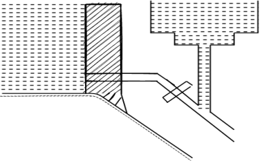
Forebays:-it is a small water reserve air at the end of water passage from reserve air and before the water is fed to turbine through penstock.it stores water when load on the plant reduces and these started water can be supplied to the turbine when load increases so it act as temporary regulating reserve air.
● When the loads on the turbine decreases the gates supplying water to the turbine are closed so it reduces water flow and pressure increases in the penstock
● This sudden action is called as water hammer
● On the other hand when load on the turbine increases the gates supplying water to the turbine are suddenly open
● So what arise from penstock to the turbine and vacuum is created in the penstock.
● Due to sudden decrease in the lord on the turbine penstock is subjected to the positive pressure (water hammer) and due to sudden increases in the load on turbine penstock is subjected to negative pressure.
● Hence surge tank is used located near the power house on high ground to provide better regulation of water pressure in system.
● When turbine gates are closed and water flow to the turbine reduces, water increases in the search think so velocity of the water into the penstock reduces.
● As soon as this velocity of the water reduces to the value corresponding to the level of turbine level of water into the surge tanke reduces and fluctuates up and down until its motion is stamped out by fiction.
● On the other hand when the load increases on the turbine additional water flows from surge tank to turbine.
● This producers accelerating head which increases the velocity of water in the penstock
● Surge tank help in reducing the water hammer effect and the velocity and pressure in the penstock
Waterway and penstock
● To water way is used to flow the water from dam to the power house.
● It includes canal and penstock (closed pipe) or (tunnel).
● Penstocks are made up of steel or reinforced can concrete (which are designed to withstand the high pressure)
● Paint stocks are supported by anchors.
● Sharp bends should not be there into the penstock because it can create hydraulic losses.
Spillways
● It is used to discharge the flood water and to keep the level of water below the designed maximum level in the reservoir.
● So spillways are used to protect the dam from damage during floods
Power house
● It contains hydraulic and electric equipment when water energy is converted to electrical energy.
● It is usually located underground whenever possible like Koyana power house in Maharashtra.
Hydraulic turbines
● It is used to convert kinetic energy of the water into mechanical energy
Draft tube
● It is a passage which connects the exit from the turbine runner down to the tail race water level
● Other purpose of the draft tube is to permit the setting of runner of reaction turbine wheel at the level above that of water in the tail race under high water and flood conditions of the river.
Trial race
● Trial race is the waterway to discharge the water from turbine to river.
● Spillways are provided to discharge the flood water during the rainy season if the water level raises above the design the maximum level in the reservoir solid gravity or over all spillways.
1) Excess water above the full reserve air flows over the crest in the form of rolling sheet.
2) This spillway is built within the body of dam.
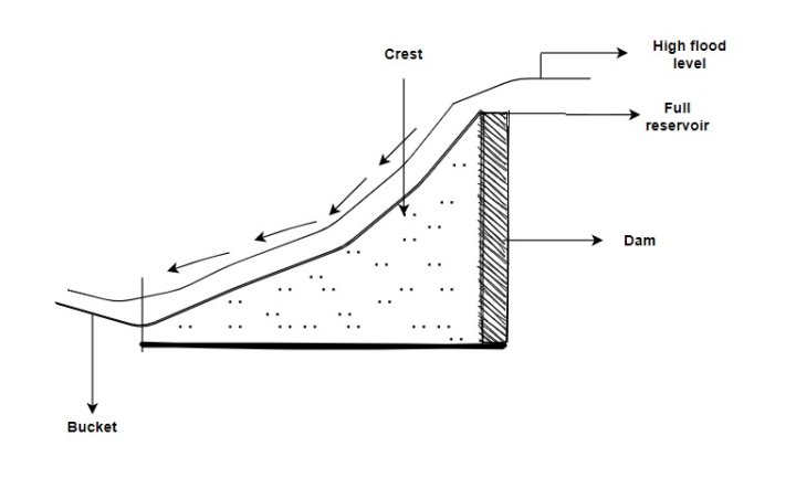
3) The water bucket provided at the end of spillway changes the direction of fast moving water and its energy is destroyed
Trough or chut spillway
● it is similar to the solid gravity or over or spillway only the difference is that at the end of spillway tough or channel is provided to meet the river channel downstream of the dam.
● such type of spillways are suitable for the construction when the valley is too narrow to accommodate the overall spillway in the body of dam
Side channel spillway
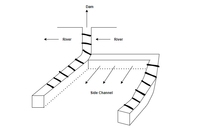
● Such spillways are provided in a situation when the valley is too narrow to accommodate even the tough or chute spillway.
● By using the side channel spillway the undesirable flow of water over the dam is avoided
● The flow of water in the site channel is either used as a channel or it meets the river or downstream side
Saddle spillway
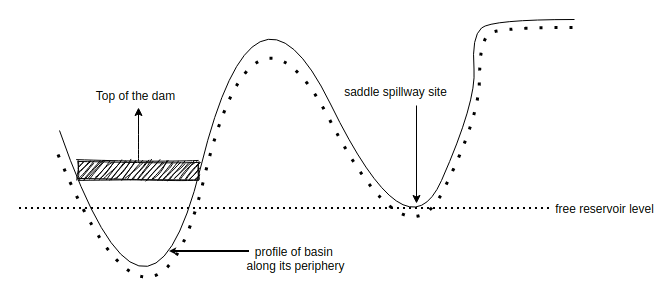
● When any of the above types of spillways are not favourable the saddle spillways are constructed.
● Where maybe some natural depression or saddle on the periphery or reserve air away from the dam.
Shaft spillway
● The shape of spillway is like a funeral constructed adjoining the dam.
● Its lower and is turned at right angles and is taken out horizontally below the dam
● The excess water above the reserve a level spill over the circular raised and then enters into the vertical shaft finally this water flows below the dam and comes out horizontally in a tunnel which meets the downstream water.
Siphon spillway
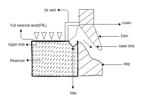
● It is constructed in the form of Siphon as shown in the figure the crest of the spillway is kept at full reserve a level of water.
● In case if the water rises above frl,it enters into the spillway and discharge through the siphon.
● If the water level falls below the lower end of the upper limb, the air enters into the lower limb and its shops the siphon action hence it stops the flow of water from reserve air
● The upper limbs kept slightly below frl so that floating debris and foreign material does not enter into the siphon.
Intake - Gates on the dam open and gravity pulls the water through the penstock, a pipeline that leads to the turbine. Water builds up pressure as it flows through this pipe.
Outflow - Used water is carried through pipelines, called tailraces, and re-enters the river downstream.
The water in the reservoir is considered stored energy. When the gates open, the water flowing through the penstock becomes kinetic energy because it's in motion. The amount of electricity that is generated is determined by several factors. Two of those factors are the volume of water flow and the amount of hydraulic head. The head refers to the distance between the water surface and the turbines. As the head and flow increase, so does the electricity generated. The head is usually dependent upon the amount of water in the reservoir.
Reduction in load on the generator causes the Governor to close the turbine gates and thus create an increased pressure in the penstock. This may result in water hammer phenomenon and may need pipes of extraordinary strength to which stand it otherwise penstock may burst.
To avoid this positive water hammer pressure, some means are required to be provided for taking the rejected flow. this may be accomplished by providing a small storage Reservoir or tank for receiving the rejected flow and thus relieving the conduit pipe of excessive water hammer pressure. Is storage Reservoir called the surge tank is usually located at close to the power station at possible, preferably on ground to reduce the height of the tower.
A decrease in load demand causes rise in water level in the Surge tank. This produces a retarding head and reduces the velocity of water in the penstock.
Increase in load on the plant causes the Governor to open the turbine Gates in order to allow more water to flow through the penstock to supply the increased the load and there is a tendency to cause a vacuum or negative pressure in the penstock.
Again under such conditions the additional water flows out of the surge tank.
Thus surge tank helps in stabilizing the velocity and pressure in the penstock and reduces water hammer and negative pressure or vacuum.
Numerical 1:-Hydroelectric power station is supplied from a reservoir of capacity  at the head of 150. Determine the total energy available in kWh if the overall efficiency of the plant is 70%.
Solution-
Water head, H=150 m
Quantity of water, 
Density of water, w=1000 kg/
Overall efficiency of the plant, =70%=0.7
Electrical energy available=wQH watt-secs


 kWh
kWh
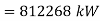
Numerical 2:- Hydroelectric power plant operates under an effective head of 50 m and a discharge of 94  . Determine the power developed.
Solution-
Discharge, 
Head, 
Density of Water, 
Power developed, 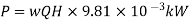


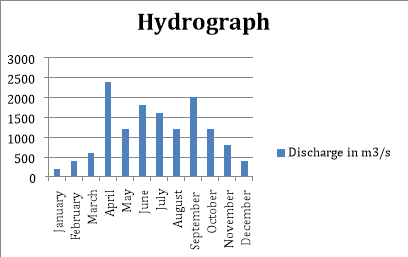
Numerical 3:-The mean monthly discharge at a particular site is given below:
Month | Discharge in  | Month | Discharge in  |
January | 200 | July | 1600 |
February | 400 | August | 1200 |
March | 600 | September | 2000 |
April | 2400 | October | 1200 |
May | 1200 | November | 800 |
June | 1800 | December | 400 |
Draw the hydrograph, flow duration curve and mass curve.
Determine the average inflow and the power that can be developed at an effective head of 90 m. Determine the capacity of the storage Reservoir based on the above 1 year data neglecting the losses due to seepage, evaporation etc. Assume overall generation efficiency to be 80 %.
Solution-
The average in flow is obtained by adding the 12 monthly charges and dividing by 12
Average inflow, 

Power developed, 

The hydrograph is plotted using the table given in the numerical.
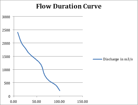
From the hydrograph plotted, the flow duration curve can be drawn by finding the length of time, during which certain flows are available. This information is tabulated in the following table and the flow duration curve is plotted.
Discharge in m3/s | Duration in Months | Percentage Time |
200 | 12 | 100.00 |
400 | 11 | 91.67 |
600 | 9 | 75.00 |
800 | 8 | 66.67 |
1200 | 7 | 58.33 |
1600 | 4 | 33.33 |
1800 | 3 | 25.00 |
2000 | 2 | 16.67 |
2400 | 1 | 8.33 |
During January, February and March, the discharge being less 950, e 750 E and 550 the excess discharge during.
The excess discharge during April, May, June, July, August, September and October would completely filled the reservoir so that the deficiency during November and December of the Year and January, February and March of next year can be made by drawing water from reservoir.
The storage capacity of the Reservoir is evidently the excess flow during April, May, June, July, August, September and October i.e.
Total of 3350 second-meter-months.
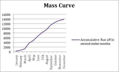
To obtain mass curve the total second meter months at the end of various months of the Year are determined as below.
Months | Discharge in m3/s | Accumulative Run off in second-meter-months |
January | 200 | 200 |
February | 400 | 600 |
March | 600 | 1200 |
April | 2400 | 3600 |
May | 1200 | 4800 |
June | 1800 | 6600 |
July | 1600 | 8200 |
August | 1200 | 9400 |
September | 2000 | 11400 |
October | 1200 | 12600 |
November | 800 | 13400 |
December | 400 | 13800 |
Reference Books:
- [R1] Arora and Domkundwar, “A Course in Power Plant Engineering”, DhapatRai Publication.
- [R2] Dr. S. P. Sukhatme, “Solar Energy”, Tata McGraw Hill Publication.
- [R3] Mukund Patel, “Wind and Solar Power Plants”, CRC Press.
- [R4] Gilbert Masters John, “Renewable Energy”, Wiley and sons’ publications.
- [R5] Robert Foster, Majid Ghassemi, Alma Cota “Solar Energy” CRC Press


