Unit 1
Thermal power plants
Thermodynamics cycles:-
Basic terms:-
1) Thermodynamics:-
The branch of science which deals with the study of different forms of energy and quantitative relationship between them.
2) Types of thermodynamics process:-
The thermodynamic occurs when system changes from initial state to the final state.
1) Isothermal process:-
When the temperature of the system remains constant during the process known as thermal process.
Heat may flow in or out of the system during isothermal process.
2) Adiabatic process:-
No heat can flow from the system to surrounding or vice versa in adiabatic process.
3) Isochoric process:-
It is the process during which volume of system remains constant.
4) Isobaric process:-
It is the process during which the pressure of the system remains constant.
5) Reversible process:-
The process which is carried out infinitesimally slowly so that all changes occurring in the direct process can be reversed and system remains constant or in almost a state of equilibrium with the surrounding at every stage of process.
6) Isentropic process:-
It is an idealized thermodynamics process that is both adiabatic and reversible. The work transfers of the system are frictionless and there is a no transfer of heat or matter.
The term isentropic means the constant entropy.
7) Entropy:-
It has no limits or requirements and its change is measured by the division between the heat change of chemical process and the temperature.
8) Enthalpy:-
Enthalpy is the measure of the heat change of the reaction occurring at the constant pressure.
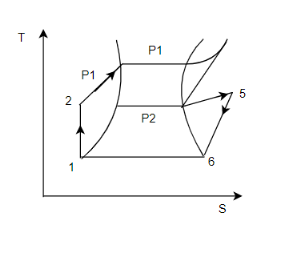
Carnot cycle:-
It is the most efficient cycle operating between specified temperature limits.
Process 1 to 2 :-
1) White vapour at pressure pv dryness is compressed in a vapour compressor isentropically (reverse adiabatically up to boiler process P such that it becomes saturated liquid).
2) The work supplied is wp and the temperature of the steam is increased for 
Process 2 to 3:-
1) Saturated liquid enters the boiler where heat is absorbed isothermally at t.
2) At temperature  steam becomes dry saturated represented by step (3) steam being in a vapour state, its temperature
  and pressure
  remains constant.
Process 3 to 4:-
1) Saturated dry steam at pl enters the steam turbine where heat expands isentropically up to the condenser pressure Pb and work  temperature of steam drops from
Process 4 to 1:-
The wet steam enters the condenser where it rejects heat  isothermally. Also at constant pressure to the cooling water circulated in condenser.
Then system returns to the original state 1.
Advantages of rankine cycle over Carnot cycle:-
1) It is not practically possible to build the power plant on carnot cycle, due to its inherent difficulties in carrying out the process of condensation and compression.
2) A carnot cycle cannot use superheated system due to practical difficulty of healing the steam isothermally with expansion in the boiler. (No such difficulty is experienced in Rankine cycle)
3) The work ratio is very high as compared to the carnot cycle since the pump work is small compared to compression work in case of carnot cycle.
4) Steam red (SR) for Rankine cycle is low compared to carnot cycle.
5) The main advantage of Rankine cycle with reheaters is it prevents vapor condensation which damages turbine plate.
6) High turbine efficiencies can be achieved by using superheated system.
7) long plant lives are achieved due to reduction in turbine erosion and low mechanical stresses.
Latent heat of vaporization:-
1) It is defined as the heat required to change the one mole of liquid at its boiling point under standard atmospheric pressure (Kg/mol)
2) When material is in liquid state is given energy, it changes its face from liquid to vapour and the energy absorbed in this process is called as heat of vaporization.
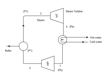
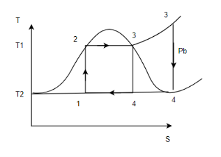
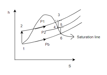
The Rankine cycle is an ideal reversible cycles for steam power plant corresponding to carnot cycle.
The cycle consists of following processes.
Process 1-2
Pumping of feed water to boiler from pressure Pb to pl, compression process is reverse adiabatic.
Process 2-3
Conversion of feed water into steam at constant pressure equal to boiler pressure p1 the heat supplied during the process is q1.
Process 3-4
Reversible adiabatic (isentropic expansion) of the system in turbine from boiler pressure p1 to back pressure pb (condenser pressure Pb or exhaust pressure) Turbine work is (
Process 4-1
The steam is condensed at constant pressure in condenser steam rejects the latent heat of vaporization to the cooling water=
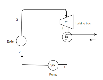
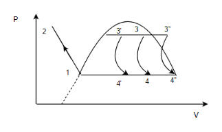
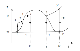
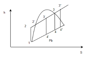
1) We can improve the efficiency of Rankine cycle by reheating the steam in between the stages of expansion.
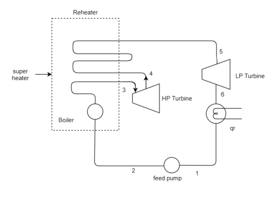
2) In this cycle the steam is extracted after the expansion in Hp turbine at a suitable point and these steam is heated in the reheater at constant pressure usually to its original temperature so that 
3) The reheating of stream in reheater is either done with the help of flue gases from the boiler furnace or in separate super heater by other sources of heating like electric heating.
Advantages of Reheat cycle:-
1) It improves the condition of steam at the the exhaust of Lpturbine so that the tendency of blades erosion caused by the liquid particles in the Lp turbine is reduced.
2) The desirable maximum moisture in the steam is considered to be 10 to 12%.
3) it improves the thermal efficiency of plant since the additional heat is supplied at higher temperature.
4) It increases the output of turbine.
5) It reduces the steam rate/kWh.
Disadvantage:-
1) Increase in the cost and size of the plant due to inclusion of reheater and its long piping.
2) It increases the size of condenser based on unit mass flow of the steam due to improved quality of steam at exhaust from Lpturbine.
Heat rate is one measure of the efficiency of electrical generators/power plants that convert a fuel into heat and into electricity. The heat rate is the amount of energy used by an electrical generator/power plant to generate one kilowatthour (kWh) of electricity.
The U.S. Energy Information Administration (EIA) expresses heat rates in British thermal units (Btu) per net kWh generated. Net generation is the amount of electricity a power plant supplies to the power transmission line connected to the power plant.
To express the efficiency of a generator or power plant as a percentage, divide the equivalent Btu content of a kWh of electricity (3,412 Btu) by the heat rate. For example, if the heat rate is 10,500 Btu, the efficiency is 33%. If the heat rate is 7,500 Btu, the efficiency is 45%.
The maximum (or ideal) heat engine efficiency (Emax).
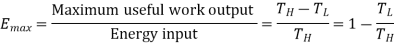
In a power plant, the steam from the boiler reaches the turbine at a temperature of 700 °C. The spent steam leaves the turbine at 100 °C. Calculate the maximum efficiency of the turbine.
Solution.
From the above expression and noting that 700 °C = 973 K and 100 °C = 373 K, we have:

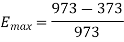
= 0.62 (62%)
1) Availability of raw material
Modern steam power plants using coal or oil as fuel require very large amount of fuel per annum.
On rough estimates, a steam power plant of 300 MW capacity requires about 3000 tones of coal per day. Therefore it is necessary to locate the plant as far as possible near to the coal fields to reduce the cost of transportation as fuel.
2) Nature of land and its cost
- The site selected should have high bearing capacity of at least 10
 to withstand dead load of the plant. It would reduce the cost of the foundation of plant.
 - To reduce civil engineering cost, the land selected should not need much leveling off site i.e. it should not require filling or blasting.
3) Availability of water:-
- Steam power plants use water as working fluid which is repeatedly evaporated and condensed. It also needs about 2% of steam generated as makeup water due to its loss. Also considerable amount of water is needed for condenser setting steam in condenser.
Therefore, it is necessary to locate the thermal power plant near a place where required.
Thermal power plant
4) Load centre:-
- Power plant must be located near to load to which the power is supplied. However, it is not possible to locate the power plant near all load.
- The location of plant at C.G. Of loads reduces The lost of transmission line and losses occurring in it.
5) Transportation facilities:-
The power plant should be located where the adequate transport facilities are available for transportation of fuel and heavy machinery for installation.
6) Future expansion:-
The site selected should be such that it allows economic extensions of the plant with the estimated growth of loads.
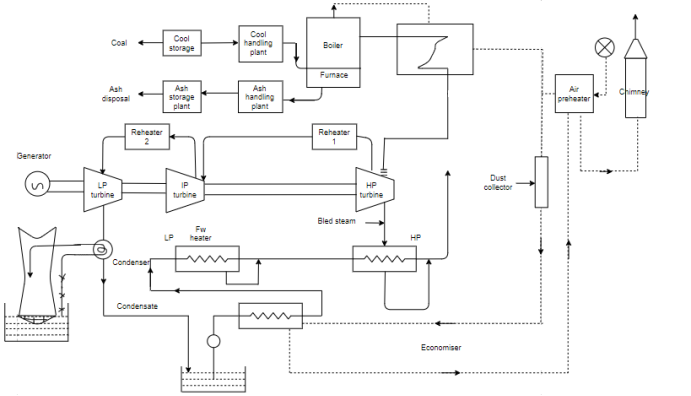
Cool and ash circuit:-
Coal is first collected in coal storage system by coal handling process through fuel handling devices. Then this coal is supplied to boiler furnace after combustion of coal, ash is collected from the boiler furnace.
Through ash handling equipment it is removed to ash storage yard.
Air and gas circuit:-
Air from the atmosphere is supplied to a combustion chamber of the boiler through the action of force draught/ or induced draught fan. First year is passed through air preheater where it is heated by the heat of flue gases(which are then pass through chimney) then this air is passed through the boiler. High temperature flue gases which are formed in the combustion chamber of the boiler are used for transferring heat to the feed water and steam in the boiler tubes and steam in the super heater tubes.
The flue gases caring ash are passed through dust collector device in order to remove the ash and finally these are passed over economizer and air preheater.
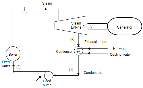
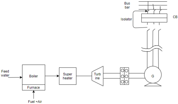
Feed water and steam circuit:-
Steam generated in the boiler tubes and superheated in super heater tubes is fed to high pressure.  turbine to develop mechanical power when steam is expanded in hp turbine.
1) A part of steam is bled for feed water heating in Hp feedwater heater.
2) And remainder is passed through reheater for reheating the steam.
This steam is now passed through the intermediate pressure turbine for further expansion. After expansion,
1) Part of steam is bled for feed water heating in Lp feed water heater.
2) And remainder is given to low pressure turbine for further expansion.
Mechanical power developed by turbine is supplied to alternator (generator) where mechanical energy is converted to electrical energy.
Cooling water circuit:-
We have to condense the steam of exhaust through condenser the quantity of cooling water required to be circulated in the condenser is about 50 kg of cooling water per kg of steam.
This water is taken from various resources live river, lake or see, if sufficient quantity of water is not available the heated water (coming out from the condenser) is cooled in the cooling towers by elaborated cooling and it is recirculated to cooling. Condensers maybe
1) Direct or jet type condenser.
2) Indirect type or surface type of condenser.
Jet condenser or direct condenser:-
In this type the exhaust steam and the cooling water comes in direct contact and as a result steam is condensed.
The temperature of the condensate and the coolant is same i.e. while leaving the condenser. So it is called as direct contact condensers. These condensers can’t bi used more because condensate collected can't be reused due to impurities of the coolant in the condenser. So it will reduce the efficiency of boiler because the impure condensate will corrode the plant tubes and will give rise to scale formation in the boiler tubes.
If the condensate is to be used as feed water to the boiler it is essential that the cooling water is treated before it is supplied to the condenser such condensers are used for small power plants.
Surface condensers (in direct type)
These are used in plants where the tubes water flows in the tubes and exhaust steam is passed over the tubes.
The exhaust steam being pure can be used as a feed water in the boiler.
Advantages:-
1) thermal power station has less initial cost as compared to hydroelectric power station.
2) Less space required as compared to HPS.
3) Fuel cost is less as compared to gaps.
4) It can be located at any location irrespective of coal mines. The coal can be transported to the site by rail or road.
5) huge amount of power can be generated.
Disadvantages:-
1) Running cost is more than Hps.
2) Pollution occurs due to smoke fumes flue gases.
3) Maintenance cost is more.
4) Coal and ash handling process is a serious problem.
5) Large quantity of water is needed.
6) Skilled persons are required for etecting and maintaining the power station.
7) Starting time is very high (6-7 hrs) from cold condition hence not suitable for peak loads.
8) Efficiency is quite low.
Feed water treatments:-
1) Mechanical
2) Thermal
3) Chemical
1) Mechanical:-
1) Sedimentation
2) Coagulation (Al, sulphate, sodium) etc.
3) Filtration
2) Thermal
1) Dearation process
2) Evaporation process
3) Chemical
1) Internal
2) External
Thermal process (treatments):-
1) The dissolved gases like  air and other gases are responsible for corrosion because these gases reacts with impurities and forms acids.
2) Sothe gases areremoved from the water before supplied to boiler by the methods of thermal treatments.
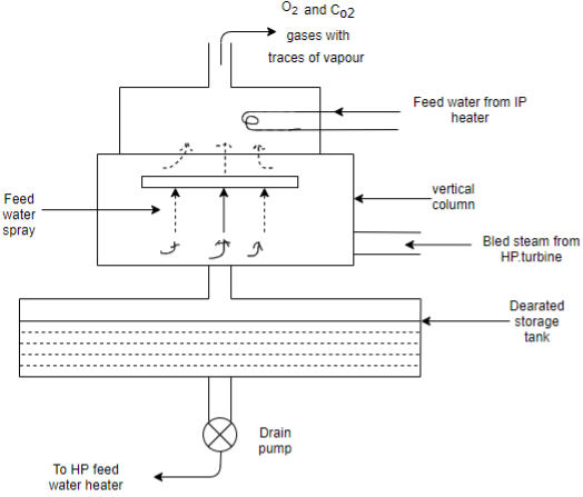
A) DEARATION PROCESS:-
1) It is also called as degasification process as mentioned above it is the most important method of feed water treatment. For the removal of 
2) Because this gases make the water corrosive (as they react with metal to form iron oxide)
3) the presence of these dissolved gases in water decreases with increase in the temperature and their magnitude becomes almost negligible at about 100°C (saturation temperature of steam at atmospheric pressure)
4) Feed water from ( heater is spread from the top and the bleed system Hp turbine from the bottom of the dearator.
5) These two comes in direct contact and as a result steam condenser and feed water is heated.
6) The dissolved gases along with vapours are released during heating and removed from the dearator from top connection.
7) The dearator works at about 1 to 1.25 bar (medium pressure) (40-50) bar and dearatorworks at about 5-8 bar for the high pressure boiler (greater than or equal to 100°)
B) Evaporation method:-
1) This method is used when the makeup water requirement for the boiler are smaller.
2) The pretreated water (raw water) is evaporated with the help of bled steam from the boiler.
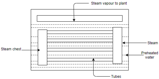
3) Both evaporated water and condensed steam from evaporator are fed back to steam power plant as a makeup water.
4) In this evaporator, pretreated raw. Water is supplied from the above and bled steam is fed into steam chest.
5) The steam flows into the tubes and transfers heat to the outside raw water and get condensed.
6) The water gets evaporated from the top of the surface into the vapour which are withdrawn and supplied to the plant.
7) The condensate along with pure saturated water is returned to boiler and makeup water.
Chemical treatments:-
A) Internal treatments:-
1) It is a suitable treatment for feeding the water to boiler (up to 20 bar pressure)
2) In this suitable salts(responsible for scale formation) are converted to soluble compounds.
3) These compounds are removed from the boiler by blow down process.
4) Various reagents like trisodium phosphate and disodium phosphate are added to keep this sludge in the fluid stage.
5) It prevents the sludge from adhering to boiler surface.
B) External treatments:-
1) these treatments are carried out externally in a tank where the raw water is received and the reagents are mixed.
2) in addition to accelerate the process of water treatments, water is heated before the addition of agents.
3) Some of the methods are
a) Lime soda treatments
b) Zeolite treatments
Assessments of heat recovery systems:-
1) The condensation of steam in condenser requires about (15Kg) of cooling water/Kg of steam.
2) This waste energy is dissipated to the conventional bodies like rivers, lakes, ponds and sea.
3) Alternately it is dissipated to the surrounding in cooling towers by heated air.
4) This waste energy (as latin heat) in exhaust steam can be utilized or received in the following ways.
a) Utilizing waste heat in process industries like paper, textile, chemical industries for heating purpose.
b) Using heat recovery boiler to generate. The organic fluids for further generation of the power.
Fuel handling:-
The steam power plant usually operates on the following type of fuels
1) Solid fuel (i.e. coal)
2) Liquid fuel (i.e. oil)
3) Gaseous fuel (i.e. natural gas)
A major amount of operating cost of Tps involves the cost of fuel handling system. It depends on the location of plant.
1) Storage of fuel
2) Rate at which fuel is bum.
Coal transportation:-
1) A large amount of coal per day is needed for the large capacity power plants.
2) The coal is transferred from the coal mines to the site of power station.
Following are methods:-
1) Sea or river
2) By rail
3) By roadways
4) By pipelines
3) the coal is transported by ships to the power plant which is nearer to the sea share.
4) for the power plants away from mines the coal is transported to main or nearest station. From their by small rail lines or by roadways, the coal is transported to the small power plants.
5) The coal transportation by pipeline is the most economical and speedy method.
Advantages of coal transportation by pipeline
1) More reliable
2) Easy to install
3) Noise and dust problem is considerable e reduced
4) Supply is continuous
5) Economical over large distances
6) Labour requirement is low
7) Loss of coal by theft during the transportation is totally avoided.
8) Safety in operation.
Requirements of good coal handling plant:-
1) It should be reliable.
2) It should require less maintenance.
3) It should be simple in construction.
4) It should have minimum where in running equipments. Due to the action of coal particles.
5) There should be the continuous supply of coal as demand of power plant.
Coal handling:-
1) The demand of coal for large power plant is very high about 7200 tonnesof cal per day is required for 600 Mow power plant.
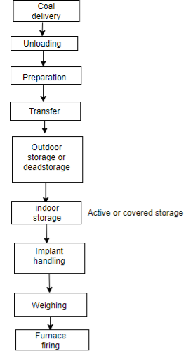
1) Coal delivery:-
The coal from coal mines is transported to the plant by ships, boats, rails, roads, trucks (when a rail facility is not available)
2) Unloading:-
1) The unloading is totally depends on the medium of transport of coal to the power plant.
2) When ship is used then unloading treatments are.
a) Coal towers
b) Unloading bridges
c) Coal asterators
d) Portable conveyors
e) Self unloading boats
3) If a coal is delivered by trucks there is no need of unloading device, because trucks can unload coal to the outdoor storage directly.
4) When coal is draught by railways weagonsthen unloading devices are
a) Car shakes
b) Rotary car dumpers
3) Preparation:-
1) The cold that we get from the coal mines is of different sizes and shapes.
2) But this is not only suitable for feeding into furnace of boiler, hence the coal is processed in this cluster to get required size.
3) Then crushed coal is passed through sizers which removes the coal of bigger sizes than required.
4) Transfer:-
Some equipments are used to transfer the coal are as follows:-
1) Belt conveyors:-
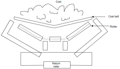
1) Smooth and clean operation.
2) Cheap maintenance
3) Low cost and low power consumption.
4) Large quantity coal can be handled continuously.
5) Rate of coal transfer can be changed by changing belt speed.
6) Maximum inclination of the belt conveyors for the transfer of coal is 20°, it runs at the speed of 400-500 Rpm. It can transfer the coal 50000 Kg/hrto 100000 Kg/hr continuously.
2) Screw conveyor:-
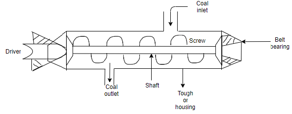
1) It requires small space.
2) Cheap
3) Simple and compact.
4) It can be made dust tight.
1) It requires high power consumption/tonn of coal transfer.
2) Wear and tear of screw is high.
3) Can be used for the transfer of coal over short distances.
Bucket elevator:-
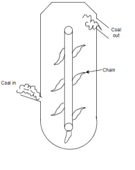
1) It consists of rotating chain structure.
2) Coal is going inside of elevator from one side and going outside from another side.
3) As the chain rotates the coal is used in forward direction and then outside of the bucket elevator.
4) In this way the coal is transferred to the site.
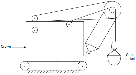
Grab bucket elevator:-
Flight conveyors or scrappers:-
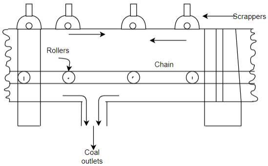
1) It consists of two or more stands of change to which steel scrappers are attached.
2) This scrapper scratches the coal at identical shape.
3) The coal is discharged in the bottom.
Advantages:-
1) It can transfer ash and coal.
2) Low capital cost.
Disadvantages:-
1) More wear and tear.
2) High maintenance cost.
Skip hoist method:-
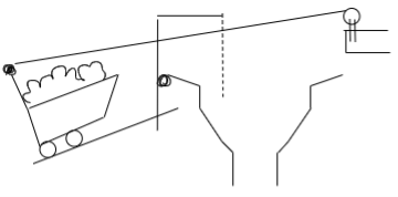
1) This is the most conventional method, old and simplest method of transfer of coal.
2) It is used for high lifts.
3) Simple, cheap and low operation and maintenance cost.
Cold storage:-
1) Outdoor coal storage.
A) Stalking the calls in piles:-
1) In this process of cold storage the coal is stored in the form of piles up to the height of 10 to 12 meter directly on the concrete ground surface to avoid the flow of air from bottom.
2) These piles consists of thick and compact layer of coal so that air can pass to coal piles.
B) Underwater storage:-
1) In this system coal is stored under water to avoid spontaneous ignition particularly in case of Ignite coals.
2) Indore/live/active coal storage:-
1) In this process coal is stored in vertical cylinders bunkers or cold bins.
2) These bunkers are usually made of steel or reinforced concrete to store the live coal.
3) Protective coating is given to inside of these bunkers to avoid corrosion due to sulphur present in the coal.
4) In Indore coal storage system the coal is stored in the plant for 2 to 3 days as per requirements of power plants and this requires negligible handling of coal.
Difference between outdoor and indoor coal handling
Sr. No. | Outdoor handling | Indoor handling |
1. | There is a large effect of weathering deterioration on coal. | There is a less effect of weathering or deterioration on coal. |
2. | Coal is usually kept on ground in the form of pile for long time | Coal is stored for one or two days as per requirements of the power plant. |
In plant handling:-
1) It means feeding of coal from live storage to furnace.
2) It is done through belt conveyors, screw conveyors.
Coal weighing:-
1) different methods are used to measure the weight of coal at the delivery point and for the amount of coal fired in the various boilers.
2) In general movable weight lorry is used to weight the coal.
Cool weighing methods:-
1) Mechanical
2) Pneumatic
3) Electronic
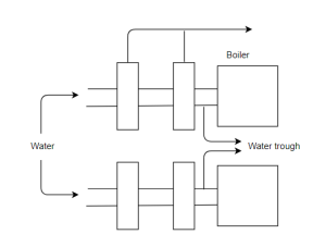
Super heaters:-
1) Super heater is a heat transfer device which consists of set of tubes.
2) The wet steam flows through these tubes and takes up heat from the flue gases passing over the steam pipe.
3) During this process wet steam is converted into superheated steam.
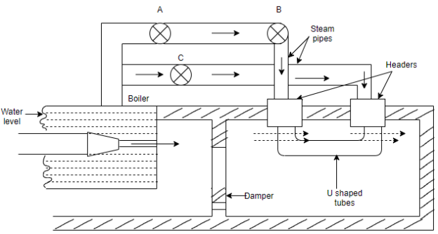
4) These tubes are made up of steel in U shape which are connected to two main headers.
5) Stop valve A is closed and B&C are open then wet steam flows from boiler to the right hand header through stop valve B
6) If superheated steam is not required stop valves B&C are closed and a is open then steam is directly taken out from stop valve A.
7) Superheating of steam can be controlled by controlling the quantity of flow of flue gases by operating the damper manually.
8) After superheating the steam in tubes, it flows into the left hand header and it is withdrawn from stop valve B.
9) the function of the super heater is to increase the temperature of steam above the saturation temperature.
10) It improves the overall thermal efficiency of plant.
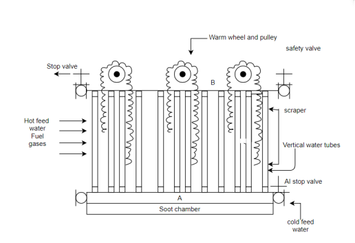
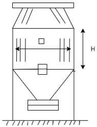
Economizer-
1) Economizer is there is a heat transfer device to heat the feed water by the heat of flue gases.
2) It consists of a large number of vertical tubes joint with the horizontal pipe at the bottom and B at the top.
3) Cold feed water is pumped into horizontal pipe a through stop valve.
4) hot flue gases from the boiler passes over this vertical tube and these gases transfer heat to the cold water in the tubes.
5) Finally the feed water is heated and these hot feed water is again provided to boiler through valve of pipe B.
6) Safely valve is mounted to the other end of the pipe be to prevent the system from extra increasing high pressure.
7) Sootformation in the tube will affect the thermal conductivity and so heat transfer rate decreases and decrease the efficiency of economizer.
8) scrappers of two adjoining pipes are coupled by rod and change and this change process over the pulley.
9) Scrapers are provided to remove the deposit of soot from each vertical tubes these scrappers slide over the pipe by worm wheel and pulley arrangement at the rate of 0.75 metre per minute hence sootis removed and collected in soot chamber.
Advantages:-
1) Increases steam evaporation capacity of boiler.
2) Fuel saving
3) Decrease scale formation in water tube boilers.
Air preheater:-
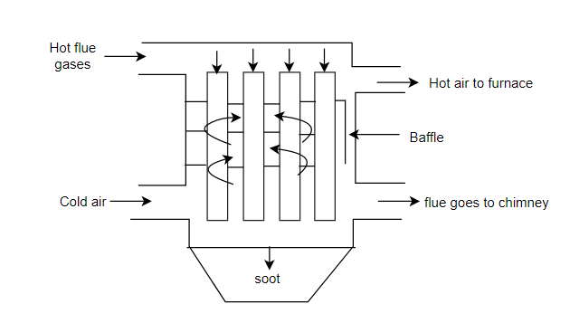
1) The device which uses waste heat of flue gases (from economiser) to heat that air to be supplied to boiler.
2) The flue gases are finally discharged to chimney from air preheater such device improves combustion efficiency of plant.
3) Hot flue gases passed through the tube and cold air is passed over the tubes.
4) Baffles are provided to increase the duration of contact for proper heat transfer between flue gases and cold air.
Ash handling system:-
Requirements of Ideal ash handling plants:-
1) Plant should be noiseless as far as possible.
2) Capital investment operation and maintenance charges should be low.
3) Equipments should be corrosion and wear resistance.
4) Equipments should be able to handle clinkers, dust particles, soot dust etc. smoothly
1) Hydraulic ash handling plant
1) Ash from the furnace grade fails into the system of water (having high velocity) and it carries ash to sums.
2) In sums water and ash are separated.
3) The ash is them loaded to wagons or trucks by means of belt conveyors or grab bucket and transferred to dumpsite (materials used for trough and sums should be corrosion and where resistance because when ash dissolved into the water it forms acid).
Advantages:-
1) Used for large power plants
2) Clean, dust less and totally indoor.
3) Doesn't harm working people in the system.
Pneumatic ash handling systems:-
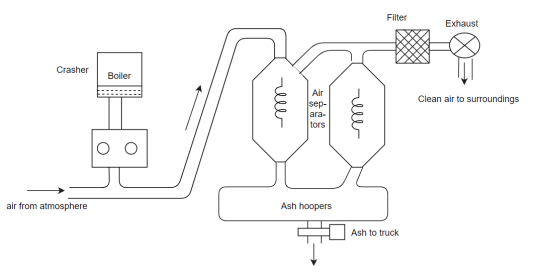
1) Ash from the boiler furnace. Falls into the crusher where large as particles are divided into small ash particles.
2) A high velocity air stream created by an exhausted carries and ash and dust particles to primary separators.
3) ash is collected in ash hooper the air with left over as passes to the secondary as separator.
4) The air leaving the separator is passed through the filter which again removes the dust particles.
5) Hence clean and clear air is passed to the atmosphere through exhauster.
Advantages:-
1) Used when ash has to be transported at considerable distance from the site.
2) Cheap and occupies less space.
3) System can handle fine and abbressive dust
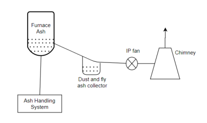
Mechanical ash handling system:-
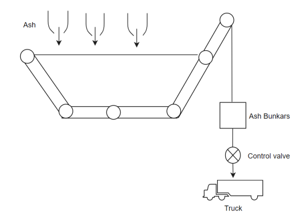
1) The hot ash released from the boilers is furnace is allowed to fall over the belt furnace conveyors. After cooling it through water.
2) This cold ash is transported through belt conveyors and falls in ash bunkers.
3) From ash bunkers ash is removed to dumping site with the help of truck.
Draught system:-
1) draught system is required to provide the sufficient amount of air for the proper combination of fuel to furnace grade.
2) Draught system is necessary for
i) To draw resultant gases from the system.
Ii) To discharge these gases from chimney to surrounding.
Iii) It is required to maintain the static pressure difference at grade which will cause the flow of air and gases take place.
Iv) This static pressure difference maintenance is called as boiler draught.
Natural draught:-
1) It is called as also chimney draught.
2) static pressure difference is developed into the chimney due to the difference in weight column of hot gases inside the chimney and weight of equal column of cold air outside chimney.
3) As density of cold air outside chimney is greater than the density of hot gases into the chimney, it follows that pressure just outside the level of chimney base would be greater than pressure inside chimney at its base.
4) this pressure difference is responsible for the flow of air from the surrounding to furnace grate.
5) The amount of draught produced by the chimney depends on
i) Chimney height
Ii) Temperature of flue gases
Iii) Temperature of surrounding cold ash.
Where,
H=height of chimney
 =temperature of cold air
 temperature corresponding to 0°c 273 Kelvin
 =mean temperature of hot gases inside the chimney.
h=draught required in mm or water coil.
m=mass of air supplied per kg of fuel
m+1=mass of flue gases per kg of fuel.
Artificial draught:-
1) The draught required to natural power plant is sufficiently high (300 mm of water) and to meet the high drought requirement or the system, there should we use of artificial draught than natural draught.
It is also called as mechanical or forced draught.
2) Because of insufficient head and lock of flexibility the use of natural draught is limited to small capacity boilers only.
A) Forced draught:-
1) In forced draught system, blower (fan) is installed near the base of boiler and air is forced to pass through the furnace, economiser, air preheater and two stack.
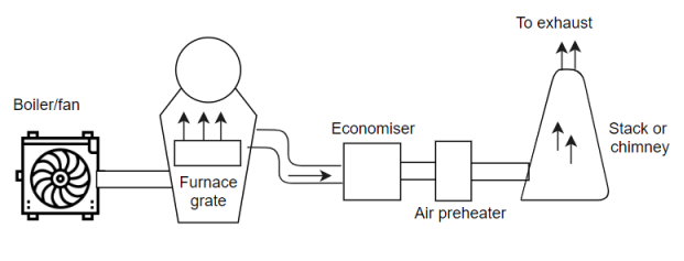
2) This draught system is also known as positive draught system be cause the air is forced to flow to the system.
3) The function of chimney is to discharge the gases, high in the atmosphere to prevent contamination.
4) The chimney is not much significant for producing draught in this type. So height is chimney is a not very much.
B) Induced draught:-
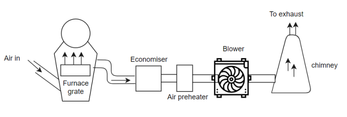
1) In this system the blower is located near the base of the chimney and air is sucked in the system.
2) induced draught fan sucks the bond gases from the furnace and pressure inside the furnace is reduced below the atmospheric pressure.
3) This induces the atmospheric air to flow through this furnace.
4) The action of induced draught is similar to action of the chimney.
5) the draught produced by the system is independent of temperature of hot gases.
6) Total draught produced in induced draught system is the sum of droughts reduced by the ton and the chimney.
C) Balanced draught:-
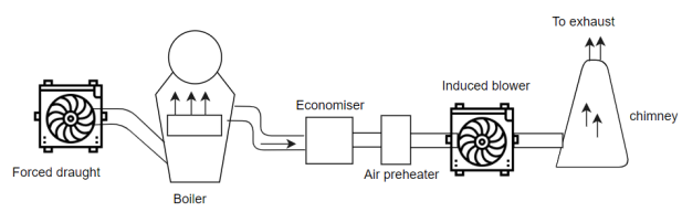
1) Instead of using forced draught or induced draught alone it is always preferable to use the combination of both.
2) If the forced draught is used alone than furnace can't be opened either for fitting for inspection, because the high pressure air inside the furnace will try to blow out suddenly.
3) And there is a chance of blowing out the fire completely and furnace stops.
4) If induced draught is used alone than the furnace can't be opened for firing or inspection, because the cold air will try to rush into the furnace as the pressure inside the furnace is below the atmospheric pressure.
5) It reduces the effect of drought and reduces combustion.
6) To overcome these difficulties we have balanced draught. The forced draught overcomes the resistance of fuel belts so sufficient air is supplied to fuel belt for proper and complete combustion.
7) The induced draught fan removes the gases from furnace and maintain the pressure in furnace below atmospheric pressure.
8) This prevents flow of flames when doors are open as to leakage of air is inward direction.
Advantages of artificial draught:-
1) It reduces smoke.
2) Reduces necessary height of chimney.
3) It provides better control of combustion and increases plant and combustion efficiency.
4) It increases the evaporative capacity of boiler due to increase in quantity of fuel burner per metre square of grate area.
5) It allows to burn the low gradefuel also.
Disadvantages of artificial draught:-
1) Initial installation cost is low but the running cost is more due to blowers ( as per is required)
2) Maintenance is high due to wear and repair.
Electrostatic preceptor:-
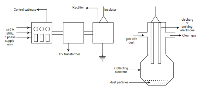
1) Dr FG Cottrell had introduced the electrostatic precipitator in 1905 and commercialized in 1937.
2) It consists offsets of electrodes insulated from each other one set is of electrical parallel plates called as collection electrodes.
3) The second set of electrodes consists of wires called as discharge for emitting electrodes.
4) The emitting electrodes posses negative high voltage (40-80Kv) from external DC source.
5) The dust laden gas is passed between two sets of oppositely charged electrodes and gas becomes ionised.
6) the positive and negative ions are formed positive ions travel to the negatively charged wire electrodes (discharged).
7) the electrons follow the electric field towards grounded electrons but their velocity decreases as they move away.
8) Gas molecules captures the low velocity electrons and becomes negative ions.
9) When these ions move to the collecting electrodes they collide with fly ash particles in the gas and give them negative charge.
10) the negatively charged fly ash particles are driven to the collecting plate by electrostatic force and separated from the gas.
11) The use of electrostatic precipitator is increasing day by day due to strict pollution.
Boiler classification: -
Boiler is a device used for producing steam under pressure.
Boilers are classified on various basis: -
1) Depending upon position of water and flue gases.
A) Fire tube boiler
In this type of boilers hot gases or flue gases from the furnace are passed through the tubes surrounded by the water outside which is to be evaporated.
Eg.
Cochron boiler,
Lancashire boiler
Locomotive boiler
B) Water tube boiler
In this boilers water to be evaporated passes through the tubes and gases from the furnace are passed over the furnace of the tubes.
Eg
Babcock
Willcocks
Stirling
2) Depending upon the position of furnace
A) Internally fired boilers
In this the furnace is inside the body of boiler shell
Eg
Loncashire
Locomotive
B) EXTERNALLY FIRED BOILERS
In this the furnace is outside the boiler shell.
Eg
Stirling
Babcock Willocks
Loeffler
3) Depending upon the position of axis of the boiler
A) Vertical boiler:-
In this type axis of the boiler shell is in vertical plane.
B) Horizontal boilers:-
In this type axis of the boiler shell is in horizontal plane.
4) depending upon the service in which the boilers are like in stationary portable
Eg
Locomotive
Marine
5) Depending upon the sources of the heat
Sources of heat may be due to
A) Heat generated due to combustion of solid liquid and gaseous fuel.
B) Hot waste gases or electrical energy or atomic energy.
6) According to the method of circulation of water and steam
A) Natural circulation:-
In case of natural circulation of steam boilers are the water is circulated by natural circulation convection which are set up due to heating of water.
Water flows from high density to low density.
Eg.
Babcock will cocks boilers
B) Forced circulation:-
In forced circulation of boiler, the water is circulated with the help of centrifugal action pump driven by external source of power. Search method of water circulation is usually employed in high pressure boilers.
Eg
Lamont boiler
Loeffler boiler
7) According to the nature of drought employed
When the fuel is burnt on the furnace of boiler due to natural circulation of air, the drought is called as natural or chimney draught.
If the air is circulated driven by external source of power is called as artificial draught.
8) According to the pressure of steam generated
The boilers which generates steam at less than 20 bars pressure are caused as low pressure boiler.
Eg .
Cochron
Lancashire
Locomotive
The boilers which produce steam above 20°p are called as high pressure boilers.
Eg.
Babcock Wilcock
Stirling
Lamont
Dust collection system:-
- The flue gases which are generated in coal fired boilers contain certain particles of solid matter is called as smoke or dust.
- Fly ash remains in suspension with flue gases.
- If the particles in suspension have the size from 1 to 100 microns it is called as dust or smoke.
- If the particles have size more than 100 microns it is sinder.
- It is very necessary to clean the gas from dust, smoke or sinder particles before it is to be discharged through chimney.
Types:-
- Electrostatic dust collector.
(Electrostatic precipitator)
- Mechanical dust collectors.
Mechanical dust collectors are classified as
1.Dry type (gravitational and Cyclone separators)
2. Wet type scrubers.
- Dry type
Gravitational dry type dust collector:-
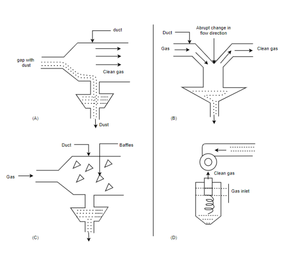
1) The basic principle of dry type dust collector is shown in figure a,b&c
2) The gas with dust is passed through the passage of in these area in order to reduce the velocity of the gas with dust.
3) Hence the heavy dust particles are separated and are collected separately.
Cyclone type mechanical dust collector:-
1) Figure is shown in D
2) The laden gas is passed in a vortex along the sides of coal.
3) The cleaned gas leaves in the inner vortex. Up words and the dust is collected at the bottom.
4) the performance of the cyclone dust collector depends on the volume of gas handled, diameter to height ratio of the cyclone chamber, inlet velocity and temperature, loading of the dust particles in the gas & gas characteristics.
Advantages:-
1) It is easy to operate.
2) Simple and cheap
3) Maintenance cost is low.
4) Dust and Sinder particles can be removed easily by this method.
5) Efficiency increases with increased loading of dust particles.
Disadvantages:-
1) It requires power to operate, hence operational cost is more as compared to other type of dust collectors.
2) Efficiency is low when it operates with very fine dust particles.
3) It requires more space.
Wet type (scrabblers):- dust collectors:-
1) In this type, dust is washed by water sprays.
2) this method of dust collection is not suitable for large power plant because huge quantity of water is required.
3) Polluted water (waste water) is generated. These polluted waters should be chemically neutralized before discharging it into the water body.
4) Cost increases to build such plants.


