Unit – 1
Introduction
System programming involves designing and writing computer programs that allow the computer hardware to interface with the programmer and the user, leading to the effective execution of application software on the computer system. Typical system programs include the operating system and firmware, programming tools such as compilers, assemblers, I/O routines, interpreters, scheduler, loaders and linkers as well as the runtime libraries of the computer programming languages.
System programming is a collection of programs that support a computer's activities. This program allows the user to concentrate on an application or a problem that needs to be solved. System programs (such as compilers, loaders, macro processors, and operating systems) were created to better adapt computers to their users' needs.
Component of System Software:
System software is a type of computer program that is designed to run a computer’s hardware and application programs. If we think of the computer system as a layered model, the system software is the interface between the hardware and user applications.
Components are:
● Text editors
● Loaders
● Assemblers
● Macro processors
● Compilers
● Debuggers
● Machine Structure
● Machine language and Assembly Language.
Key takeaway:
System programming involves designing and writing computer programs that allow the computer hardware to interface with the programmer and the user, leading to the effective execution of application software on the computer system.
The system program is an operating system component. It sits between the user interface and the system calls in most cases. System programs, not system calls, determine the user perspective of the system because that is what they engage with because system programs are closer to the user interface.
System programs create an environment in which programs can be written and run. System programs, in the most basic sense, serve as a link between the user interface and system calls. They are, in fact, far more complicated. A compiler, for example, is a sophisticated system software.

Fig 1: Software hierarchy
System software - system software controls for processing activities and make sure that resources and the power of the computer are used in the most efficient manner. The major purpose of system software is to control the execution of program and help in the development of software.
Function of system software
- Supports the development of other application software.
- Support the execution of other applications software.
- Monitors the effective use of various hardware resources such as CPU, memory, Peripherals etc.
- Communicates with and controls the operation of peripheral devices, such as printer, disk, tape etc.
Types of system software
System software can be classified into three categories
- Operating system
- Language processor
- Utility software
● Operating system - An operating system is a series of programs which organizes and controls a computer. an operating system is a master control program that runs the computer and at as a scheduler. it controls the flow of signals from the CPU to various part of the computer.
Some tasks are as follows
- Operating system control the hardware such as keyboards, the printer and the screen.
- Operating system perform job scheduling and monitoring.
- Operating system control the processes that store data on disk and take data from disk.
- Controls the operation of application software.
- Organize the hard and floppy disk, so they can store data.
● Language processor or language translator - A translator is a program which convert statement written in one language into statement in another language.
Assembler - An assembler is a program that convert program written in assembly language in equivalent machine code so that computer can understand and execute it.
Compiler - Compiler translate whole high level language source code into to a machine code. This object code is loaded into memory after linking process and is executed.
Interpreter - Interpreter translate one statement at a time of the High-level language source program into a machine code. This object code is loaded into memory and it is executed later on next statement it is read and is translated and executed.
● Utility software - It is a set of programs that support the operating system by providing the additional services that the operating system does not provide. There are many tasks which are performed by utility programs some are hard disc backup, disk Optimization, File recovery, safe formatting and resource editing. utility software is also known as service program aur utility routine. It is specially designed to help in managing and tune the computer hardware, operating system or application software, and perform a single task or a small range of task. Some important utilities are disk defragmenter, virus scanner/ antivirus, disk compression, file management tools, file manager etc.
Application Software: Application software products are created to meet a specific need in a specific setting. Application software encompasses many of the software programs produced in the computer lab. Typical applications include word processing, medical software, database, educational software etc. Applications are almost always independent programs from the operating system.
Customized or general-purpose application software is usable.
● Customized Application software: The software which is developed to meet all the requirements of a specific user or organization. For example, software prepared to automate the result process of any institute is an application software.
● General Application software: The software which is developed by keeping all the general requirements in mind for carrying out a specific task. These are software which are developed by a group of people. For e.g., word processing software, electronic spreadsheet etc.
The most commonly used packages are -
Word processor - A word processor manager text-based documents. It allows the user to enter, edit, view, to store and retrieve the next material. this text material may be letter, reports or book etc. word processor varies from simple to the complex. an advanced word processor must contain all the features needed for entering, editing and formatting the text as well as support macros to simplify complex or routine task. it also includes facility for spell checking, dictionary etc. Microsoft Word and what perfect are example of fully featured word processor.
Spreadsheet - The spreadsheet or worksheet consists of rows and columns of cells. the row are usually identified by number and columns by letters. each cell can hold a numeric value, text label for a formula that produce values contained in the other cells. chart can be created and database related operation could be performed. MS Excel is example of spreadsheet software.
Graphics software - A graphic software enables us to use a computer system for creating, editing, storing and viewing, printing, designing, drawing, pictures, graphs and anything else what can be drawn in the traditional manner.
Personal assistant software - A personal assistant software allows us to use personal computers for storing and retrieving our awesome information, planning and managing our schedules, contact financial and inventory of important items.
Key takeaway:
System software controls for processing activities and make sure that resources and the power of the computer are used in the most efficient manner.
Application software products are created to meet a specific need in a specific setting.
An operating system is a series of programs which organizes and controls a computer.
- System Software: The device software is a set of programs that run, monitor, and expand the computer's processing capabilities. The majority of system software is created by the computer manufacturers. The purpose of system software is to insulate the application programmer as much as possible from the details of the particular computer complex being used, especially memory and other hardware features, and such accessory devices as communications, printers, reader, keyboard etc.
- Application Software: Application software products are created to meet a specific need in a specific setting. Application software encompasses many of the software programs produced in the computer lab. Typical applications include word processing, medical software, database, educational software etc. Applications are almost always independent programs from the operating system.
Customized or general-purpose application software is usable.
● Customized Application software: The software which is developed to meet all the requirements of a specific user or organization. For example, software prepared to automate the result process of any institute is an application software.
● General Application software: The software which is developed by keeping all the general requirements in mind for carrying out a specific task. These are software which are developed by a group of people. For e.g., word processing software, Electronic spreadsheet etc.
Difference between system software and application software
System Software | Application Software |
It consists of low-level programs that Interact with the computer at the very basic level. | It sits at the top of the system Software because it is unable to run Without the operating system & system utilities. |
It controls and coordinates the computer Operations. | It is used for special and general Purpose Operations. |
Functions: □ Programs □ Manages Resources □ Controls I/O □ Communications | Function: - Word Processing - Desktop Publishing - Spreadsheets - Databases - Telecommunications |
Key takeaway:
System software controls for processing activities and make sure that resources and the power of the computer are used in the most efficient manner.
Application software products are created to meet a specific need in a specific setting.
All the conventional modern computers are based upon the concept of stored program computer, the model that was proposed by John von Neumann.
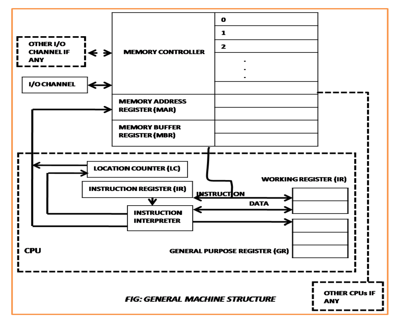
Fig 2: Machine structure
The above structure consists of
1. Instruction interpreter
2. Location counter
3. Instruction register
4. Working register
5. General register
The Instruction Interpreter Hardware is basically a group of circuits that perform the operation Specified by the instructions fetched from the memory. The Location Counter can also be called as Program Instruction Counter simply points to the current instruction being executed. The working registers are often called the “scratch pads” because they are used to store temporary values while calculation is in progress.
This CPU interfaces with Memory through MAR & MBR MAR (Memory Address Register) - contains address of memory location (to be read from or stored into) MBR (Memory Buffer Register) - contains copy of address specified by MAR Memory controller is used to transfer data between MBR & the memory location specified by MAR The role of I/O Channels is to input or output information from memory.
The following are the components of a generic machine:
Instruction interpreter: A group of electronic circuits carries out the intent of fetched from memory instruction.
Location counter: The location counter, also known as the program counter PC or the instruction counter IC, is a physical memory device that indicates the location of the currently executed instruction.
Instruction register: The instruction register (IR) stores a duplicate of the LC's content.
Working registers: are memory devices that act as the instruction interpreter's "scratch pad."
General register: Programmers use general registers as storage locations and for particular purposes.
Memory address registers (MAR): Stores the address of the memory region to be read or written to.
Memory buffer register (MBR): Stores a duplicate of the memory location whose address is stored in MAR. The memory buffer register is the principal interface between the memory and the CPU.
Memory controller: A memory controller is a hardware device that transfers the contents of the MBR to the core memory region whose address is provided in the MAR.
I/O channels: Think of I/O channels as distinct computers that interpret unique instructions for inputting and outputting data from memory.
Machine language:
Sometimes referred to as machine code or object code, machine language is a collection of binary digits or bits that the computer reads and interprets. Machine language is the only language a computer is capable of understanding.
The exact machine language for a program or action can differ by operating system on the computer. The specific operating system will dictate how a compiler writes a program or action into machine language.
Computer programs are written in one or more programming languages, like C++, Java, or Visual Basic. A computer cannot directly understand the programming languages used to create computer programs, so the program code must be compiled. Once a program’s code is compiled, the computer can understand it because the program’s code has been turned into machine language.
Machine language example:
Below is an example of machine language (binary) for the text “Hello World”.
01001000 01100101 01101100 01101100 01101111 00100000 01010111 01101111 01110010 01101100 01100100
Below is another example of machine language (non-binary), which will print the letter “A” 1000 times to the computer screen.
169 1 160 0 153 0 128 153 0 129 153 130 153 0 131 200 208 241 96
Key takeaway
The Instruction Interpreter Hardware is basically a group of circuits that perform the operation Specified by the instructions fetched from the memory.
Sometimes referred to as machine code or object code, machine language is a collection of binary digits or bits that the computer reads and interprets.
Text Editor:
A text editor is a type of program used for editing plain text files. Such programs are
Sometimes known as “notepad” software, following the Microsoft Notepad.
Assembler:
Assembler is a computer program which is used to translate a program written in Assembly Language into machine language. The translated program is called an object program. Assembler checks each instruction for its correctness and generates diagnostic messages, if there are mistakes in the program.
Various steps of assembling are:
- Input source program in Assembly Language through an input device.
- Use Assembler to produce object programs in machine language. 3. Execute the program.
Associate in the Nursing of the meeting application which may be a remotely the worm that interprets pc of the code packages inscribed therein of the programming language into the computing device language, code and instructions that might also be lifeless by using a laptop
Macro Processor:
A macro processor is a program that copies a stream of text from one place to another, making a systematic set of replacements as it does so. Macro processors are often embedded in other programs, such as assemblers and compilers. Sometimes they are standalone programs that can be used to process any kind of text.
A macro is that of a rule or sample that designates that alternatively an actual input sequence ought to be mapped to a supersession of the output sequence in step with that of an outlined procedure.
Compiler:
A compiler is a program that translates a program written in HLL to executable machine language. The process of transferring HLL source program in to object code is a lengthy and complex process as compared to assembling. Compilers have diagnostic capabilities and prompt the programmer with appropriate error message while compiling a HLL program. The corrections are to be incorporated in the program, whenever needed, and the program has to be recompiled. The process is repeated until the program is mistake free and translated to an object code. Thus, the job of a compiler includes the following:
- To translate HLL source program to machine codes.
- To trace variables in the program
- To include linkage for subroutines.
- To allocate memory for storage of program and variables.
- To generate error messages, if there are errors in the program.
Interpreter:
The basic purpose of an interpreter is same as that of compiler. In compiler, the program is translated completely and directly executable version is generated. Whereas interpreter translates each instruction, executes it and then the next instruction is translated and this goes on until end of the program. In this case, object code is not stored and reused. Every time the program is executed, the interpreter translates each instruction freshly. It also has program diagnostic capabilities. However, it has some disadvantages as below:
1. Instructions repeated in program must be translated each time they are executed.
2. Because the source program is translated fresh every time it is used, it is slow process or execution takes more time. Approx. 20 times slower than compiler.
Loaders:
A loader is the part of an operating system that is responsible for loading programs and libraries. It is one of the essential stages in the process of starting a program, as it places programs into memory and prepares them for execution. Loading a program involves reading the contents of the executable file containing the program instructions into memory, and then carrying out other required preparatory tasks to prepare the executable for running. Once loading is complete, the operating system starts the program by passing control to the loaded program code.
Loader is Associate with the nursing software program utility that will copies the programs on the fine-tuned disk to principal recollection (RAM).
In integration loader supplementally supersedes bodily addresses with logical addresses.
Linkers:
Linker is a program that takes one or more objects generated by a compiler and combines them into a single executable program. Loader is the part of an operating system that is responsible for loading programs from executables (i.e., executable files) into memory, preparing them for execution and then executing them.
It is the approach of commixing varied items of that of the code and records alongside to make that of one viable file that may additionally be reloaded into that of the recollection.
Debugger:
A debugger is a computer program used by programmers to test and debug a target
Program. Debuggers may use instruction-set simulators, rather than running a program directly on the processor to achieve a higher level of control over its execution.
It is an application wont to realize and take an optical canvassing of bugs (errors) within the programs (other programs). A programme is adscititious referred to as debugging implement.
A programme will sanction that of a coder that it will obviate that of a program at any of the purport and so the time to have a look at and alter that of the values of that of the program.
Operating system
Software is the Associate in Nursing interface between utilizer and hardware.
The operating system is as follows:
● A group of programs that assist you in using the computer.
● Acts as a smart assistant, controlling the flow of data between various components and applications.
● Manages program, data, and process usage, storage, and access. The OS performs a variety of tasks.
Key takeaway
A text editor is a type of program used for editing plain text files.
Assembler is a computer program which is used to translate a program written in Assembly Language into machine language.
A macro processor is a program that copies a stream of text from one place to another, making a systematic set of replacements as it does so.
Interpreter translates each instruction, executes it and then the next instruction is translated and this goes on until the end of the program.
1. Compilers and Assemblers
• AN program or that of a compiler is simply another program that may execute on your ADPS.
• the sole issue special that of AN program or that of a compiler is that it interprets programs from that of the one type (source code) to a different (machine code).
• A typical that of the x86 program, as an example, would browse that of the lines of text with that of the x86 directions, take apart every of that of the statement, so write the binary equivalent of every of that of the instruction on to memory or thereto that of a file for later execution.
• Assemblers have 2 massive blessings over committal to writing in machine code:
o First, they mechanically translate strings like
o add ax, bx
o mov ax, [1000h]
To their corresponding binary type.
o Second, and doubtless even that of the additional necessary, assemblers allow you to attach labels to that of the statements so consult with them in this of a jump direction
§ (A coder won't ought to recognize the target address of AN instruction once specifying targets of jump directions.)
2. The Assembly method
1. Aggregation the ASCII text file into that of AN object file
2. Linking the article file thereupon of the opposite modules or the libraries into AN workable program
3. Loading the program into memory
4. Running the program
3. Tiny Assembly Sample
; add_16_bytes.asm
;
.586P
; Flat memory model, normal career convention:
.MODEL FLAT, STDCALL
;
; knowledge section
_DATA section
Values sound unit sixteen DUP( five ); 16 bytes of values "5"
_DATA ENDS
; Code section
_TEXT section
START:
Mov eax, zero; clear result
Mov bl, sixteen; init loop counter
Lea esi, values; init knowledge pointer
Addup:
Add al, [esi]; add computer memory unit to add
INC esi; increment knowledge pointer
Dec bl; decrement loop counter
Jnz addup; if BL not zero, continue
Mov [esi], al; save add
Dowse; Exit
_TEXT ENDS
END START
• Listing file: add_16_bytes.lst
4. MASM statement Interface
• To assemble which of the run AN program program named myprog.asm, sort the subsequent commands:
• decision "C:\Program Files\Microsoft Visual Studio 8\Common7\Tools\vsvars32.bat"
• cubic centimetre /coff /c /Fl myprog.asm
• LINK /debug /subsystem:console /entry:start /out:myprog.exe myprog.obj ..\iolib\io.obj kernel32.lib
• myprog.exe
5. Assembling
• At assembly time, the assembler:
o Evaluates conditional-assembly directives, aggregation if the conditions are true.
o Expands macros and that of the macro functions.
o Evaluates constant expressions like MYFLAG AND 80H, subbing the calculated worth for the expression.
o Encodes directions and non-address operands. As an example, mov cx, 13; are often encoded at assembly time as a result of the instruction doesn't access memory.
o Saves memory offsets as that of the offsets from their segments.
o Places sections and segment attributes within the object file.
o Saves placeholders for that of the offsets and that of the segments (relocatable addresses).
o Outputs an inventory if requested.
o Passes messages (such as INCLUDELIB) on to the linker.
6. Linking
• Once your ASCII text file is assembled thereto of the ensuing object file is passed to that of the linker. At this time, the linker also mixes many object files into that of AN workable program. The linker:
o Combines segments in keeping with the directions within the object files, rearranging the positions of segments that share constant category or cluster.
o Fills in placeholders for offsets (relocatable addresses).
o Writes relocations for segments into the header of .EXE files (but not .COM files).
o Writes the result as AN workable program file.
7. Loading
• when loading that of the workable file into the memory, the in that of the operation system:
o Creates that of the program section prefix (PSP) header in that of the memory.
o Allocates memory for that of the program, supported the values within that of the PSP.
o masses the program.
o Calculates the right values for absolute addresses from the relocation table.
o masses the section registers SS, CS, DS, and Es with values that time to the correct areas of memory.
8. Helpful Tools and Utilities
• DUMPBIN dismantlement program
• Debuggers: OllyDbg and WinDbg
• Consol I/O: iolib.
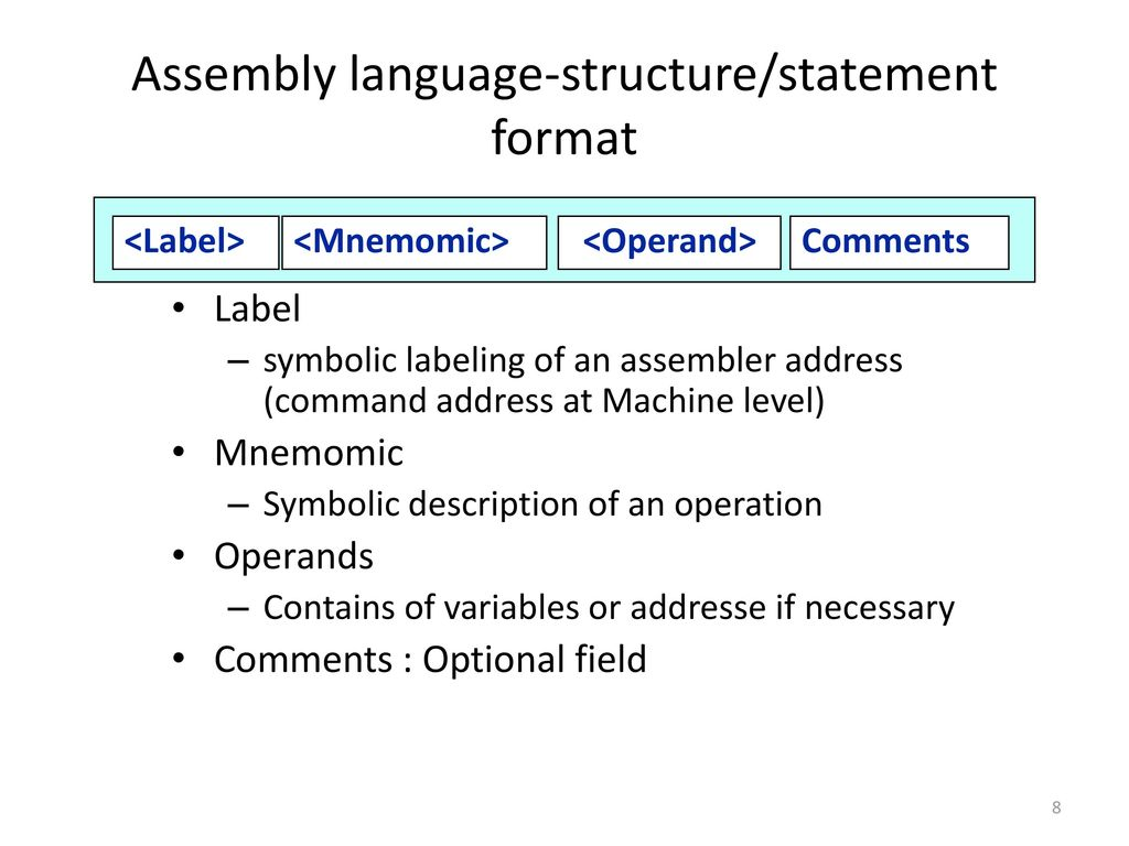
Label
Symbolic labeling of an assembler address (command address at Machine level)
Mnemomic
Symbolic description of an operation
Operands
Contains of variables or addressee if necessary
Comments
Optional field
Statement format An Assembly language statement has following format:
[Label] <opcode> <operand spec> [, <operand spec>.]
If a label is specified in a statement, it is associated as a symbolic name with the memory word generated for the statement.
<operand spec> has the following syntax:
<symbolic name> [+<displacement>] [(<index register>)]
E.g., AREA, AREA+5, AREA (4), AREA+5(4)
AREA – memory word with which name AREA is associated
AREA +5: The memory word, which is 5 words away from the word which name is AREA, here ’5’ is displacement offset from AREA
AREA (4): indexing with index register 4: the operand address is obtained by adding the content of index register 4 to the address of area
● It requires less memory and execution time;
● It allows hardware-specific complex jobs in an easier way;
● It is suitable for time-critical jobs;
● It is most suitable for writing interrupt service routines and other memory resident programs.
● Reduced errors
● Faster translation times
● Changes could be made easier and faster.
● Addresses are symbolic, not absolute \
● Easy to remember
● The use of symbolic operand specifications is one of the key advantages of assembly language programming over machine language programming.
(In comparison to a program written in machine language)
● In cases where it is desirable to use architectural aspects of a computer, assembly language programming has an advantage over HLL programming.
(When compared to a high-level language program)
● Take a look at the assembly code on the next slide. The previous slide's program computes N!, while the next slide's program computes 12 * N!, with rectangular boxes highlighting program changes.
● To implement division by two, a once statement has been placed before the PRINT command. This causes changes in the address of constants and reserve memory sections in the machine language program.
● Most of the program's instructions have to modify as a result of these addresses.
● Because operand specifications are symbolic in nature, such changes are not required in an assembly program.
A simple assembly scheme
The process of specifying an assembler is divided into two stages:
- Analysis Phase
- Synthesis Phase (the fundamental information requirements will arise in this phase)
An assembler's design specification is as follows
There are four steps to designing an assembler's specification:
1. Determine what information is required to complete a task.
2. Create an appropriate data structure for storing information.
3. Determine the processes that will be required to get and keep the data.
4. Determine the amount of processing required to complete the activity.
The essential information requirement appears during the assembler's synthesis phase. As a result, it's best to start with the information requirements of synthesis activities.
Synthesis phase
Consider the following proposition:
MOVER BREG, ONE
For this statement, the following information is required to synthesize machine instructions:
1. The address of the memory word associated with the name ONE [depends on the source program, therefore the Analysis phase makes it available].
2. The MOVER-related machine operating code [Because it is dependent on the assembly language rather than the source program, the synthesis phase may derive this information for itself].
Analysis phase
The primary goal of the Analysis phase is to create a symbol table.
- It has to figure out what addresses the symbolic names used in a program are associated with.
- Some addresses, such as the address of the program's initial instruction, can be determined directly (i.e., start).
- Additional addresses must be deduced.
- To determine the addresses of the symbolic names, we must use Memory Allocation to fix the locations of all program elements preceding it.
A data structure called a location counter is used to implement memory allocation.
Location counter (LC): The address of the next memory word in the target program is always stored in the location counter.
The constant given in the START statement is used to initialize it.
When a LABEL is met,
- it creates a new entry in the symbol table with the LABEL and the contents of LC.
LABEL – e.g., N, AGAIN, SUM etc.
- It then determines how many memory words the assembly statement need and updates the LC contents.
The lengths of the various instructions must be known by the analysis phase in order to update the contents of the LC.
- The Mnemonics table contains this information, which is supplemented with a length field.
The processing involved in maintaining the LC is referred to as LC Processing.
Pass structure of Assembler
Improve the execution speed
Register-to-register instructions
Immediate addressing: op #
Operand is already present as part of the instruction
Indirect addressing: op @m
Often avoid the need of another instruction
Key takeaway
It requires less memory and execution time.
It allows hardware-specific complex jobs in an easier way.
It is suitable for time-critical jobs.
Three Kinds of Statements
1. Imperative Statements
2. Declaration Statements
3. Assembler Directives
a) Imperative Statements: It indicates an action to be performed during the execution of the assembled program. Each imperative statement typically translates into one machine instruction.
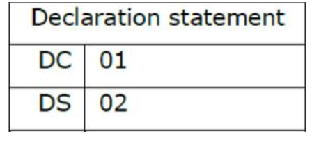
b) Declaration Statements: Two types of declaration statements are as follows
[Label] DS <Constant>
[Label] DC <Value>
The DS (Declare Storage) statement reserves areas of memory and associates names with them.
E.g. A DS 1
B DS 150
First statement reserves a memory of 1 word and associates the name of the memory as A. Second statement reserves a memory of 150 word and associates the name of the memory as B.
The DC (Declare Constant) Statement constructs memory word containing constants e.g., ONE DC ‘T
Associates the name ONE with a memory word containing the value T. The programmer can declare constants in decimal, binary, hexadecimal forms etc., These values are not protected by the assembler. In the above assembly language program the value of ONE Can be changed by executing an instruction MOVEM BREG, ONE
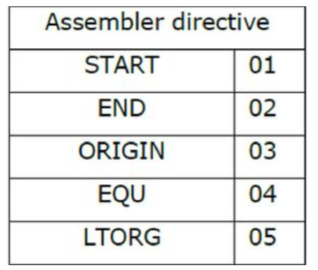
c) Assembler Directives: Assembler directives instruct the assembler to perform certain actions during the assembly of a program.
Some Assembler directives are described in the following
START <Constant>
Indicates that the first word of the target program generated by the assembler should be placed in the memory word with address <Constant?
END [ <operand spec>]
It Indicates the end of the source program
1. ORIGIN
2. EQU
3. LTROG
ORIGIN:
Syntax: ORIGIN <address spec>
<address spec> can be an <oρerand sρec> or constant
Indicates that Location counter should be set to the address given by <address spec>
This statement is useful when the target program does not consist of consecutive memory words.
Eg - ORIGIN Loop + 2
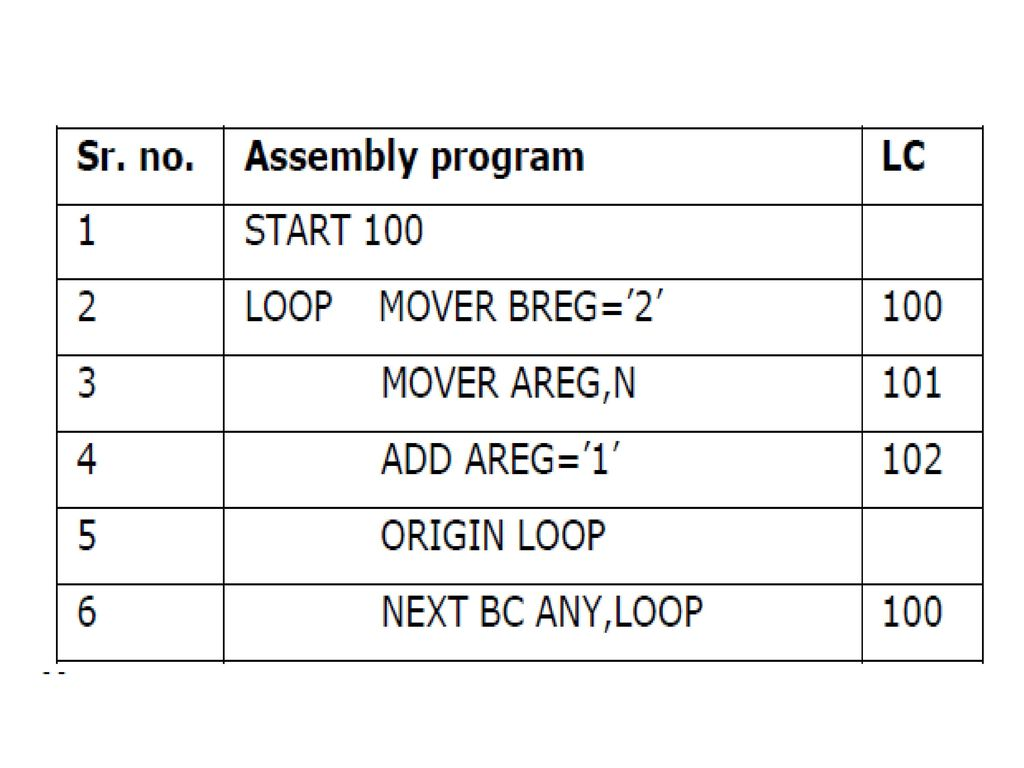
EQU:
Syntax
<symbol> EQU <address spec>
<address spec> operand spec (or) constant
Simply associates the name symbol with address specification No Location counter
Processing is implied
Eg - Back EQU Loop
LTORG: (Literal Origin)
Where should the assembler place literals?
It should be placed such that the control never reaches it during the execution of a program.
By default, the assembler places the literals after the END statement.
LTROG statement permits a programmer to specify where literals should be placed.
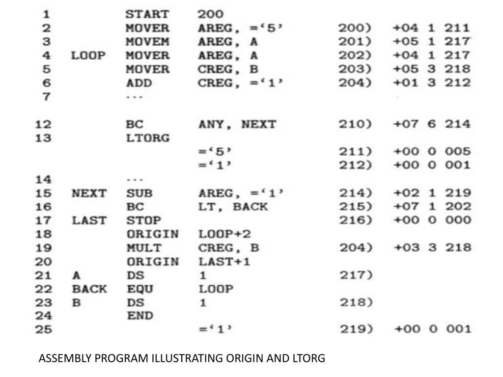
The LTORG statement allows a programmer to specify the location of a literal. Assembler defaults to placing literals after the end statement.
The assembler allocates memory to the literals of the literal pool at every LTORG statement, as well as at every END statement. Since the start of the program or the commencement of the LTORG statement, the pool holds all literals used in the program.
Literals ‘=5' and ‘=1' are added to the literal pool with addresses 211 and 212 in the preceding slide's program.
In statement 15, a new literal pool is created, and the value ‘=1' is added to it. This value is assigned to the second pool of literals at address 219, rather than the first pool's address 213.
Intermediate code is made up of a series of IC units, each of which has three fields.
1. Address
2. Representation of mnemonics opcode
3. Representation of operands

MNEMONICS filed
A pair of the form are stored in the mnemonics field.
(Statement class, code)
Where IS, DL, and AD stand for imperative statement, declaration statement, and assembler directive, respectively.
In the case of imperative statements, code refers to the machine language instruction opcode.
Code is an ordinal number within the class for declarations and assembler directives.
Assembler directive number one, which is the directive START, is represented by (AD, 01).
The table below lists the codes for various declaration statements and assembler commands.
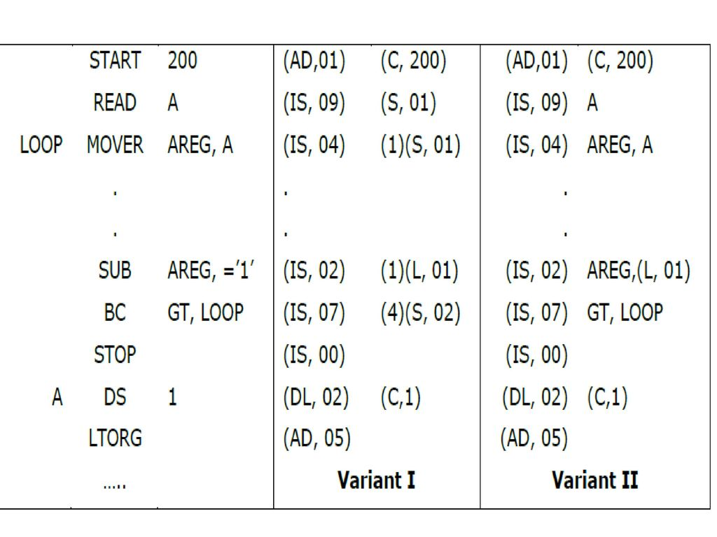
INTERMEDIATE CODE FOR IMPERATIVE STATEMENTS
Variant I
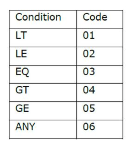
The first operand is a single digit number that represents a register code or the condition code.
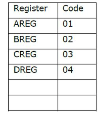
A pair of the type represents the second operand, which is a memory operand.
Where the operand class is one of C, S, or L, which stands for constant, symbol, or literal, respectively.
The code field for a constant contains the constant's internal representation.
For example, the operand descriptor for the START 200 statement is (C,200).
The ordinal number of the operand's entry in SYMTAB or LITTAB is stored in the code field for a symbol or literal.
Variant II
Variation II of the intermediate code differs from variant I in that symbol, condition codes, and CPU registers are not processed. Processing of the operand field is required to support LC processing in declarative statements and assembler directives. As a result, the processed forms are stored in this field. The operand field in imperative statements is solely used to identify literal references.
As a result, during pass I, the IC unit will not create for that.
Pass I
1. Run the source code.
2. A counter that keeps track of where each instruction is located.
3. A table, the machine-operation table (MOT), that shows the symbolic mnemonics for each instruction as well as the duration of the instruction (tow, four or six bytes).
4. The pseudo operation table (POT), which lists the symbolic mnemonics and actions to be performed for each pseudo-op in pass-1.
5. A table called the literal table (LT), which is used to keep track of each literal encounter and its allocated position.
6. A table called the symbol table (ST), which is used to keep track of each label and its associated value.
7. A copy of the input for Pass-2 to use later. This could be saved on a separate storage device.
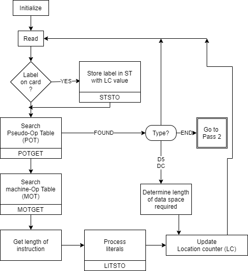
Fig 3: Pass 1 overview: define symbol
Pass II
1. Copy of source program input to pass-1
2. Location counter
3. A table the MOT that indicates for each instruction
a. Symbolic
b. Mnemonics
c. Length
d. Binary machine op-code
e. Format (RR, RS, RX, SI, SS)
4. The POT table, which shows the symbolic mnemonic and action to be taken in Pass-2 for each pseudo-op.
5. Pass-1 prepares the ST, which includes each label and its corresponding value.
6. A table, BT, that shows which registers are currently specified by the base register via pseudo-ops and what the contents of these registers are.
7. An INSR work space for storing each instruction as its various parts are put together.
8. A PRINT LINE in the workspace that is used to create a printed listing.
9. A workspace PUNCH CARD used to convert assembled instructions into the format required by the loader prior to actual outputting.
10. An output deck of assembled instruction in the format needed by the loader.
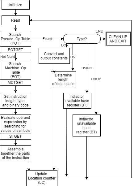
Fig 4: Pass 2 overview: evaluate fields and generate code
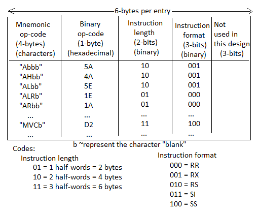
- Machine Operation Table (MOT)
Fig machine op table for pass-1 and pass-2 the op code is the key and its value is the binary op-code equivalent which is stored for use in generating machine opcode. The instruction length is saved to update the location counter, and the instruction format is saved to build the machine language equivalent.
2. Pseudo Operation Table (POT)
The physical address will be stored in the table. Each pseudo-op is provided with an accompanying pointer to the assembler procedure for executing the pseudo-op in Fig POT for pass-1.
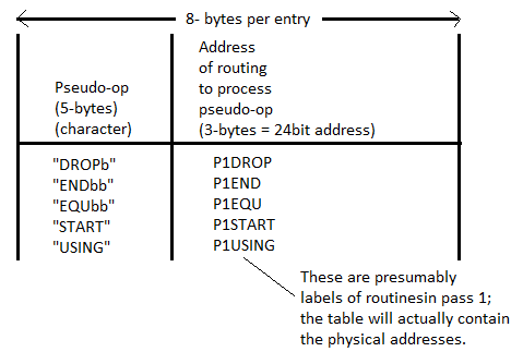
Fig 5: POT for pass 1
3. Symbol Table (ST)
In most cases, the symbol table is hash-organized. It includes all necessary information about the symbols defined and utilized in the source code. For each symbol and address in a symbol table, information about all forward references is created at random, and the information about that symbol gets the same address conflict is resolved using collision handling techniques.
The relative location indicator indicates to the assembler whether the symbol's value is absolute or relative to the program's base.
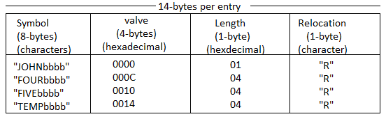
Fig 6: Symbol table for pass 1 and pass 2
4. Base Table (BT)
The assembler uses the base register table to generate the necessary base register references in machine instructions and to compute the correct offsets. When producing an address, the assembler consults the base register table to select a base register with a value close to the symbolic references. The address refers to the data stored in that base register.
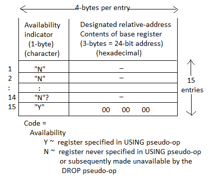
Fig 7: Base table for pass 2
Key takeaway
The symbol table is hash-organized. It includes all necessary information about the symbols defined and utilized in the source code.
The assembler uses the base register table to generate the necessary base register references in machine instructions and to compute the correct offsets.
During the development of an operating system, application, or any other software, every programmer has the possibility to encounter defects or flaws in their code. Developers utilize debugging and tools in these situations to detect problems in code and make the code or program error-free. There is a possibility to locate the bug and determine where it occurred across the application. This is an important procedure in software technology for finding problems in any new program or application process. To produce the required output, fatal and logical mistakes can be detected and deleted. GDB, Visual Studio, and LLDB are examples of standard debuggers for various operating systems.
Debugging
Debugging is a crucial approach for locating and removing the amount of errors, faults, or defects in a software. Software development is a multi-step procedure. It entails identifying the bug, tracking down the cause of the bug, and fixing the issue so that the program is error-free. The developer can use this approach to locate the code error in the program and fix it in software development. As a result, it is critical to the entire software development lifecycle.
Debugging tools
A debugger or debugging tool is a software tool or application that is used to test and debug other programs. It aids in the detection of code faults at various phases of the software development process. These tools examine the test run and identify any lines of code that aren't being performed. Simulators and other debugging tools allow the user to see how the operating system or any other computing device looks and behaves. The majority of open-source tools and scripting languages do not have an IDE and must be done manually.
GDB, DDD, and Eclipse are the most commonly used debugging tools.
● GDB tool - Unix programming makes use of this type of tool. GDB is pre-installed on all Linux computers; if it isn't, the GCC compiler package must be downloaded.
● DDD tool - DDD stands for Data Display Debugger, and it is used in Unix systems to operate a Graphic User Interface (GUI).
● Eclipse - An IDE tool combines an editor, a build tool, a debugger, and other development tools into one package. The most widely used Eclipse tool is the IDE. When compared to DDD, GDB, and other tools, it is more efficient.
GDB
In any software development system, a debugger is essential. Nobody can write bug-free code in a single sitting. Bugs are discovered during development and must be resolved in order for the product to be improved further. Without a debugger, a development system is incomplete. When it comes to open source developers, GNU Debugger is the greatest option. On UNIX-like platforms, it's also utilized for commercial software development.
GNU Debugger, also known as gdb, allows us to peek inside a program's code while it's running or see what it was trying to do right before it failed. GDB enables us to accomplish four major things in order to detect defects in source code.
● Begin the program by specifying any arguments that may have an impact on the overall behavior.
● The program will come to a halt if certain conditions are met.
● Examine the crash or the point at which the program was terminated.
● Change the code and immediately try with the changed code.
Without much effort, we can use gdb to debug C and C++ programs. Support for other programming languages such as D, Modula-2, and Fortran is currently just partial.
GDB commands
The gdb command is used to start GDB. When you run gdb, it displays some platform information before dropping you into the (gdb) prompt, as shown below.
[root@fedora20 ~]# gdb
Sample output
GNU gdb (GDB) Fedora 7.6.50.20130731-19.fc20
Copyright (C) 2013 Free Software Foundation, Inc.
License GPLv3+: GNU GPL version 3 or later
This is free software: you are free to change and redistribute it.
There is NO WARRANTY, to the extent permitted by law. Type "show copying"
And "show warranty" for details.
This GDB was configured as "x86_64-redhat-linux-gnu".
Type "show configuration" for configuration details.
For bug reporting instructions, please see:
.
Find the GDB manual and other documentation resources online at:
.
For help, type "help".
Type "apropos word" to search for commands related to "word".
(gdb)
To learn about the many kinds of commands available in gdb, type help list. For a list of instructions in that class, type help followed by the class name. To get a list of all commands, type help all. Abbreviations for command names are permitted if they are unambiguous. For example, instead of typing next, you can type n, or c for continue, and so on.
Commonly used GDB commands
The following table lists the most commonly used gdb commands. The gdb command prompt is where you'll use these commands (gdb).
Command | Description |
Run | Start a program execution |
Quit | Quit gdb |
Print expr | Print expression where expr may be a variable name too |
Next | Go to next line |
Step | Step into next line |
Continue | Continue from the current line till the end of program or next break point |
Take note of the distinction between the commands step and next. If the next line is a function call, the next command does not proceed inside the function. The step command, on the other hand, can travel into a function and examine what happens there.
Modifying variable
GDB can also change variables in the middle of a program's execution. Let's give it a shot. As previously said, place a break point on line 16 and run the program.
(gdb) r
Starting program: /root/sum
Enter the first number: 1
Enter the second number: 2
Breakpoint 1, main ( ) at sum.c:16
16 printf("The sum is %d\n\n", z);
(gdb) set z=4
(gdb) c
Continuing.
The sum is 4
Now a = 1, b = 2, and z = 3 should be the outcome. However, in the main function, we modified the final result to z = 4. Using gdb, debugging can be made easier in this fashion.
Debugging running processes
In a GNU/Linux system, many processes are operating in the background. To debug a running process, we must first get the process id of the process in question. The pidof command returns the process's pid.
$ pidof <process_name>
This pid must now be attached to gdb. There are two options.
1. By include pid in the gdb command.
$ gdb -p <pid>
2.Using the gdb attach command.
(gdb) attach <pid>
References:
- John Donovan, “Systems Programming”, McGraw Hill, ISBN 978-0--07-460482-3
- Dhamdhere D., "Systems Programming and Operating Systems", McGraw Hill, ISBN 0 - 07 - 463579 – 4
- Leland Beck, “System Software: An Introduction to Systems Programming”, Pearson
- John R. Levine, Tony Mason, Doug Brown, “Lex & Yacc”, 1st Edition, O’REILLY,
ISBN 81-7366-062-X


