Unit - 3
Types Flip Flops & Sequential Circuits
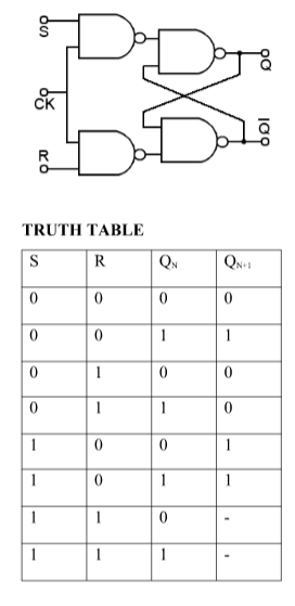
S-R Flip Flop:
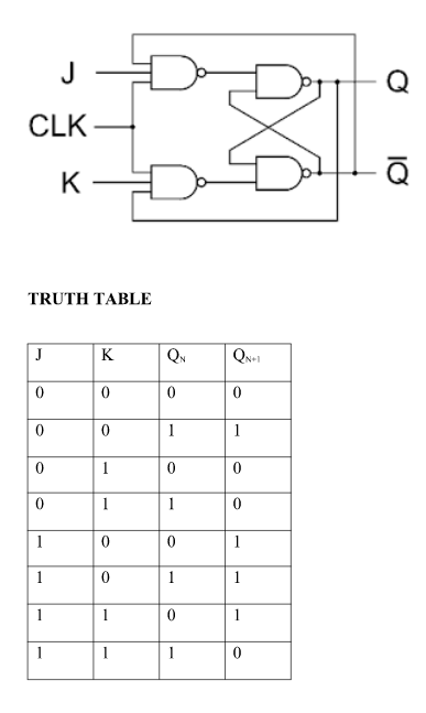
J-K Flip Flop:
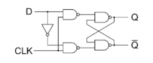
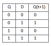
D Flip Flop
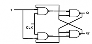
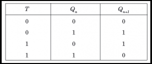
T Flip Flop
- Some flip-flops have asynchronous inputs that are used to force the flip-flop to a particular state independently of the clock
- The input that sets the flip-flop to 1 is called preset or direct set. The input that clears the flip-flop to 0 is called clear or direct reset.
- When power is turned on in a digital system, the state of the flip-flops is unknown. The direct inputs are useful for bringing all flip-flops in the system to a known starting state prior to the clocked operation.
- The knowledge of the type of flip-flops and a list of the Boolean expressions of the combinational circuit provide the information needed to draw the logic diagram of the sequential circuit. The part of the combinational circuit that gene rates external outputs is described algebraically by a set of Boolean functions called output equations. The part of the circuit that generates the inputs to flip-flops is described algebraically by a set of Boolean functions called flip-flop input equations (or excitation equations).
- The information available in a state table can be represented graphically in the form of a state diagram. In this type of diagram, a state is represented by a circle and the (clock-triggered) transitions between states are indicated by directed lines connecting the circles.
- The time sequence of inputs, outputs, and flip-flop states can be enumerated in a state table (transition table). The table has four parts present state, next state, inputs and outputs.
- In general, a sequential circuit with 'm' flip-flops and 'n' inputs needs 2m+n rows in the state table.
Conversion for Flip Flops
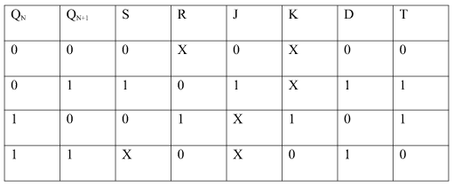
Excitation Table:
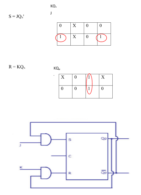
i) SR To JK Flip Flop
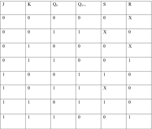
Excitation Functions:
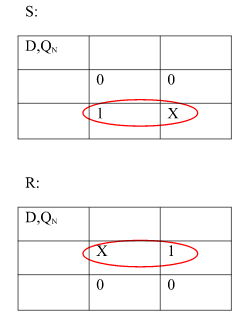
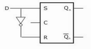
Ii) Convert SR To D Flip Flop:
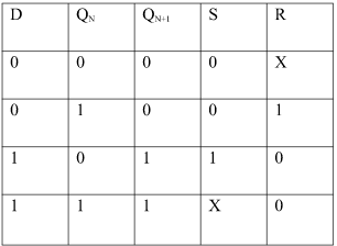
Excitation Functions:
S = D
R = D‘
Master slave JK flip flop
- It is basically a combination of two JK flip-flops connected together in series.
- The first is the “master” and the other is a “slave”.
- The output from the master is connected to the two inputs of the slave whose output is fed back to inputs of the master.
- In addition to these two flip-flops, the circuit comprises of an inverter.
- The inverter is connected to clock pulse in such a way that an inverted clock pulse is given to the slave flip-flop.
- In other words, if CP=0 for a master flip-flop, then CP=1 for a slave flip-flop and vice versa.
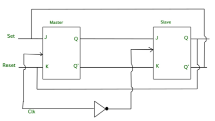
Fig. Master Slave Flip flop
Working of a master slave flip flop –
- When the clock pulse goes high, the slave is isolated; J and K inputs can affect the state of the system. The slave flip-flop is isolated when the CP goes low. When the CP goes back to 0, information is transmitted from the master flip-flop to the slave flip-flop and output is obtained.
- The master flip flop is positive level triggered and the slave flip flop is negative level triggered, hence the master responds prior to the slave.
- If J=0 and K=1, Q’ = 1 then the master goes to the K input of the slave and the clock forces the slave to reset therefore the slave copies the master.
- If J=1 and K=0, Q = 1 then the master goes to the J input of the slave and the Negative transition of the clock sets the slave and thus copy the master.
- If J=1 and K=1, the master toggles on the positive transition and the slave toggles on the negative transition of the clock.
- If J=0 and K=0, the flip flop becomes disabled and Q remains unchanged.
Timing Diagram of a Master flip flop –
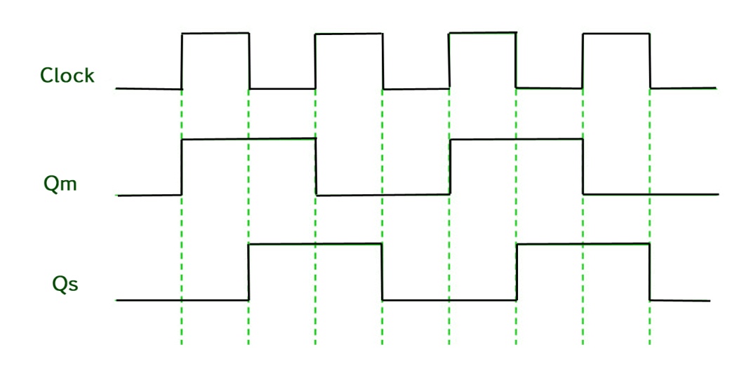
- When the CP = 1 then the output of master is high and remains high till CP = 0 because the state is stored.
- Now the output of master becomes low when the clock CP = 1 and remains low until the clock becomes high again.
- Thus toggling takes place for a clock cycle.
- When the CP = 1 then the master is operational but not the slave.
- When the clock is low, the slave becomes operational and remains high until the clock again becomes low.
- Toggling takes place during the whole process since the output changes once in a cycle.
- This makes the Master-Slave J-K flip flop a Synchronous device which passes data with the clock signal.
Race around Condition (Racing)
- For J-K flip-flop, if J=K=1, and if clk=1 for a long period of time, then output Q will toggle as long as CLK remains high which makes the output unstable or uncertain.
- This problem is known as race around condition in J-K flip-flop.
- This problem can be avoided by ensuring that the clock input is at logic “1” only for a very short time.
- Hence the concept of Master Slave JK flip flop was introduced.
3.2 Sequential Circuits: Counters
A Counter stores the number of times a particular event or process has occurred in relationship to a clock signal.
They are used in digital electronics for counting purpose.
They can count specific event happening how many times in the circuit.
For example, in UP counter count increases for every rising edge of clock.
A counter can follow certain sequence based on our design like any sequence 0,1,3,2… .
They can be designed with the help of flip flops.
Counter Classification
Counters are broadly classified into two categories:
- Asynchronous counter
- Synchronous counter
- It counts ten different states and then reset to its initial states.
- A simple decade counter will count from 0 to 9 but the decade counters which can go through any ten states between 0 to 15(for 4 bit counter) can also be made.
Truth table is as follows:
Clock pulse | Q3 | Q2 | Q1 | Q0 |
0 | 0 | 0 | 0 | 0 |
1 | 0 | 0 | 0 | 1 |
2 | 0 | 0 | 1 | 0 |
3 | 0 | 0 | 1 | 1 |
4 | 0 | 1 | 0 | 0 |
5 | 0 | 1 | 0 | 1 |
6 | 0 | 1 | 1 | 0 |
7 | 0 | 1 | 1 | 1 |
8 | 1 | 0 | 0 | 0 |
9 | 1 | 0 | 0 | 1 |
10 | 0 | 0 | 0 | 0 |
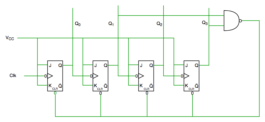
Fig. Decade counter
In the above circuit diagram we used nand gate for Q3 and Q1 and sending this to clear input line as the binary representation of 10 is—
1010
And Q3 and Q1 are 1 here, if we give NAND of these two bits then counter clears at 10 and again starts from the beginning.
1. Asynchronous Counter
In this universal clock is not used and only the first flip flop is driven by main clock and the clock input of rest of the following is driven by output of previous flip flops.
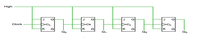
Fig. Asynchronous counter
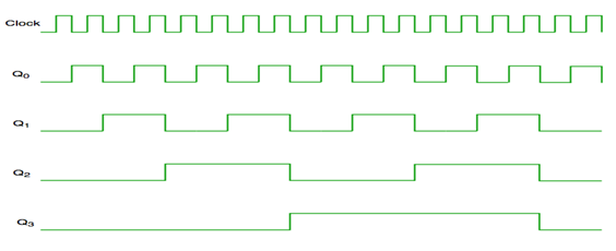
Fig. Timing diagram of Asynchronous counter
It is seen from timing diagram that Q0 is changing as soon as the rising edge of clock pulse is encountered.
Q1 is changing when rising edge of Q0 is encountered and so on.
In this way ripples are generated through Q0,Q1,Q2,Q3 and therefore it is also called as a RIPPLE counter.
2. Synchronous Counter
It has one global clock which drives each and every flip flop and hence output changes in parallel.
The advantage of synchronous counter over asynchronous counter is that it can operate on higher frequency and it does not have cumulative delay .
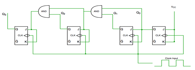
Fig. Synchronous counter
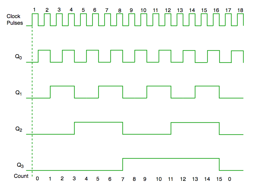
Fig. Timing diagram of synchronous counter
References:
1. Modern digital Electronics- R. P. Jain, McGraw Hill.
2. Digital Integrated Electronics- Herbert Taub, McGraw Hill.
3. Digital Logic and Computer Design- Morris Mano (PHI).
4. Digital Integrated Electronics- Herbert Taub, McGraw Hill.
5. Digital Electronics Logic and System – James Bingnell and Robert Donovan, Cengage Learning.


