Unit - 1
Boolean Algebra, Types of Number Systems, Types of Codes and Forms of Expression
Analog | Digital |
An analog signal is a continuous signal that represents physical measurements. | Digital signals are time separated signals which are generated using digital modulation. |
It is denoted by sine waves | It is denoted by square waves |
It uses a continuous range of values that help you to represent information. | Digital signal uses discrete 0 and 1 to represent information. |
Temperature sensors, FM radio signals, Photocells, Light sensor, Resistive touch screen are examples of Analog signals. | Computers, CDs, DVDs are some examples of Digital signal. |
The analog signal bandwidth is low | The digital signal bandwidth is high. |
Analog signals are deteriorated by noise throughout transmission as well as write/read cycle. | Relatively a noise-immune system without deterioration during the transmission process and write/read cycle. |
Analog hardware never offers flexible implementation. | Digital hardware offers flexibility in implementation. |
It is suited for audio and video transmission. | It is suited for Computing and digital electronics. |
Processing can be done in real-time and consumes lesser bandwidth compared to a digital signal. | It never gives a guarantee that digital signal processing can be performed in real time. |
Analog instruments usually have s scale which is cramped at lower end and gives considerable observational errors. | Digital instruments never cause any kind of observational errors. |
Analog signal doesn't offer any fixed range. | Digital signal has a finite number, i.e., 0 and 1. |
Boolean Algebra is used to analyze and simplify the digital (logic) circuits. It uses only the binary numbers i.e. 0 and 1. It is also called as Binary Algebra or logical Algebra. Boolean algebra was invented by George Boole in 1854.
Rule in Boolean Algebra
Following are the important rules used in Boolean algebra.
Variable used can have only two values. Binary 1 for HIGH and Binary 0 for LOW.
Complement of a variable is represented by an overbar (-). Thus, complement of variable B is represented as  . Thus if B = 0 then
  = 1 and B = 1 then
  = 0.
= 0.
ORing of the variables is represented by a plus (+) sign between them. For example ORing of A, B, C is represented as A + B + C.
Logical ANDing of the two or more variable is represented by writing a dot between them such as A.B.C. Sometime the dot may be omitted like ABC.
The three basic laws of Boolean Algebra are:
- Commutative law
- Associative law
- Distributive law
Commutative Law
- The logical operation carried between two Boolean variables when gives the same result irrespective of the order the two variables, then that operation is said to be Commutative. The logical OR & logical AND operations between x & y are shown below
x + y = y + x
x.y = y.x
- The symbol ‘+’ and ‘.’ indicates logical OR operation and logical AND operation.
- Commutative law holds good for logical OR & logical AND operations.
Associative Law
- If a logical OR operation of any two Boolean variables is performed first and then the same operation is performed with the remaining variable providing the same result, then that operation is said to be Associative. The logical OR & logical AND operations of x, y & z are:
x + (y + z) = (x + y) + z
x.(y.z) = (x.y).z
- Associative law holds good for logical OR & logical AND operations.
Distributive Law
- If a logical OR operation of any two Boolean variables is performed first and then AND operation is performed with the remaining variable, then that logical operation is said to be Distributive. The distribution of logical OR & logical AND operations between variables x, y & z are :
x.(y + z) = x.y + x.z
x + (y.z) = (x + y).(x + z)
- Distributive law holds good for logical OR and logical AND operations.
- These are the Basic laws of Boolean algebra and we can verify them by substituting the Boolean variables with ‘0’ or ‘1’.
- It is useful in finding the complement of Boolean function.
- It states that “The complement of logical OR of at least two Boolean variables is equal to the logical AND of each complemented variable”.
- It can be represented using 2 Boolean variables x and y as
(x + y)’ = x’.y’
- The dual of the above Boolean function is
(x.y)’ = x’ + y’
- Therefore, the complement of logical AND of the two Boolean variables is equivalent to the logical OR of each complemented variable.
- Similarly, DeMorgan’s theorem can be applied for more than 2 Boolean variables also.
A digital system understands positional number system where there are few symbols called digits and these symbol represents different values depending on their position in the number.
A value of the digit is determined by using
- The digit
- Its position
- The base of the number system
Decimal Number System
- Its the system that we use in our daily life. It has a base 10 and uses 10 digits from 0 to 9.
- Here, the successive positions towards the left of the decimal point represent units, tens, hundreds, thousands and so on.
- Each and every position represents a specific power of the base (10). For example, the decimal number 4321 consists of the digit 1 in the units position, 2 in the tens position, 3 in the hundreds position, and 4 in the thousands position, and its value can be written as
(1×1000) + (2×100) + (3×10) + (4×l)
(1×10³) + (2×10²) + (3×101) + (4×l00)
1000 + 200 + 30 + 1
1234
- As a computer programmer, we should understand the following number systems used in computers.
S.N. | Number System & Description |
1 | Binary Number System Base 2. Digits used: 0 and 1 |
2 | Octal Number System Base 8. Digits used: 0 to 7 |
3 | Hexa Decimal Number System Base 16. Digits used: 0 to 9, Letters used: A- F |
Binary Number System
- It uses two digits 0 and 1.
- It is also called as base 2 number system.
- Here, each position in any binary number represents a power of the base (2). Example: 23
- The last position represents a y power of the base (2). Example: 2y where y represents the last position.
Example
Binary Number: 101112
Calculating the Decimal Equivalent of binary number −
Step | Binary Number | Decimal Number |
Step 1 | 101012 | ((1 × 24) + (0 × 23) + (1 × 22) + (1 × 21) + (1 × 20))10 |
Step 2 | 101012 | (16 + 0 + 4 + 2 + 1)10 |
Step 3 | 101012 | 2310 |
Note: 101112 is normally written as 10111.
Octal Number System
- It consists of eight digits 0, 1,2,3,4,5,6,7.
- It is also named as base 8 number system.
- Here each position represents a power of the base (8). Example: 82
- The last position represents a y power of the base (8). Example: 8y where y represents the last position.
Example
Octal Number − 125758
Calculating Decimal Equivalent −
Step | Octal Number | Decimal Number |
Step 1 | 125758 | ((1 × 84) + (2 × 83) + (5 × 82) + (7 × 81) + (5 × 80))10 |
Step 2 | 125758 | (4096 + 1024 + 320 + 56 + 5)10 |
Step 3 | 125758 | 550010 |
Note: 125758 is normally written as 12575 in octal.
Hexadecimal Number System
- It uses 10 digits starting from 0,1,2,3,4,5,6,7,8,9 and 6 letters A,B,C,D,E,F.
- These letters represents numbers as A = 10, B = 11, C = 12, D = 13, E = 14, F = 15.
- It is also known as base 16 number system.
- Here each position represents a power of the base (16). Example 161.
- The last position represents a y power of the base (16). Example: 16y where y represents the last position.
Example:
Hexadecimal Number: 19FDA16
Calculating Decimal Equivalent −
Step | Hexadecimal Number | Decimal Number |
Step 1 | 19FDA16 | ((1 × 164) + (9 × 163) + (F × 162) + (D × 161) + (A × 160))10 |
Step 2 | 19FDA16 | ((1 × 164) + (9 × 163) + (15 × 162) + (13 × 161) + (10 × 160))10 |
Step 3 | 19FDA16 | (65536 + 36864 + 3840 + 208 + 10)10 |
Step 4 | 19FDA16 | 10645810 |
Note − 19FDA16 is normally written as 19FDA in hexa decimal.
Key Takeaways:
- Binary number system: 0 and 1
- Decimal number system: 0 to 9
- Octal number system: 0 to 7
- Hexa Decimal number system: 0 to 9 and A to F
Self-complementary codes
Self-complementing binary codes are those whose members complement on themselves. For a binary code to become a self-complementing code, the following two conditions must be satisfied:
1. The complement of a binary number should be obtained from that number by replacing 1’s with 0’s and 0’s with 1’s (already stated procedure).
2. The sum of the binary number and its complement should be equal to decimal 9.
Binary Coded Decimal (BCD) code
- Here each decimal digit is represented by a 4-bit binary number.
- Its a way to express each of the decimal digits with a binary code.
- Therefore, by four bits we can represent sixteen numbers (0000 to 1111).
- But in BCD code only first ten of these numbers are used (0000 to 1001) and rest are invalid.
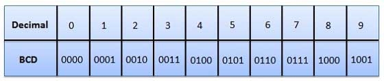
Fig.: BCD codes
Advantages of BCD Codes
- It is very similar to decimal system.
- We have to remember binary equivalent of 0 to 9 only.
Disadvantages of BCD Codes
- The addition and subtraction of BCD number system have different rules.
- The BCD arithmetic is more complicated.
- BCD code requires more number of bits than binary code to represent the decimal number.
- Hence is less efficient than binary.
Excess-3
- It is also known as XS-3 code.
- It is a non-weighted code used to express decimal numbers.
- They are derived from the 8421 BCD code words adding (0011)2 or (3)10 to each code word in 8421.
- The excess-3 codes are obtained as −
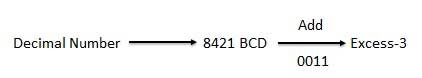
Example
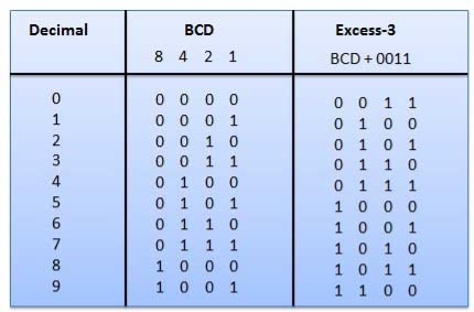
Fig.: BCD to XS 3 conversion
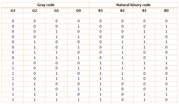
Gray codes
- It is the non-weighted code and is not an arithmetic code.
- This means that there are no specific weights assigned to the bit position.
- Here only one bit will change every time the decimal number is incremented.
- The gray code is also known as a unit distance code as only one-bit changes at a time.
- The gray code is a type of cyclic code.
- It cannot be used for all arithmetic operation.
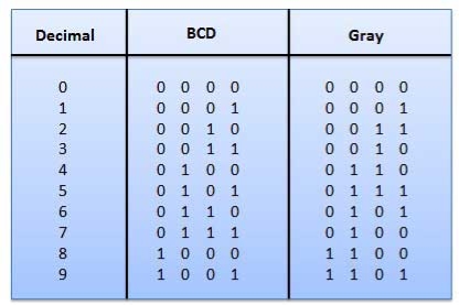
Fig: Gray codes
Application of Gray code
- They are used in the shaft position encoders.
- This encoder produces a code word which represents the angular position of the shaft.
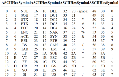
Alphanumeric codes
A binary digit orbit can be represented by two symbols as '0' or '1'.
This is not sufficient for communication between two computers as we need many more symbols for communication.
These symbols represent 26 alphabetic characters with capital and small letters, numbers from 0 to 9, punctuation marks, and other symbols.
These alphanumeric codes represent numbers and alphabetic characters.
Most of them also represent other characters like symbols and various instructions necessary for conveying information.
The code at least represents 10 digits and 26 letters of alphabet i.e., total of 36 items.
The following three types of alphanumeric codes are commonly used for data representation.
- American Standard Code for Information Interchange (ASCII).
- Extended Binary Coded Decimal Interchange Code (EBCDIC).
- Five bit Baudot Code.
ASCII code is a 7-bit code whereas EBCDIC is an 8-bit code.
ASCII code is used worldwide while EBCDIC is primarily used in large IBM computers.
ASCII Codes
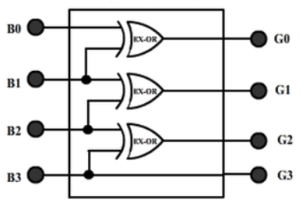
Binary To Gray Code
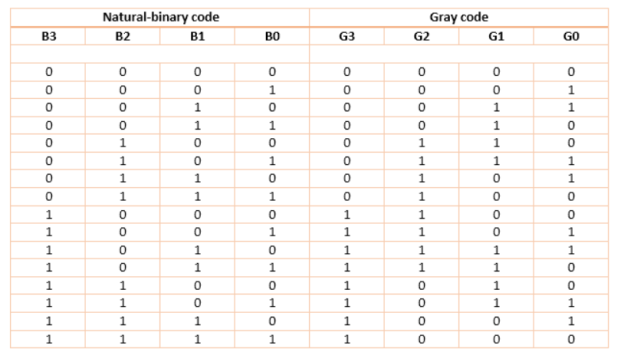
For this circuit, B3 B2 B1 B0 are inputs while G3 G2 G1 G0 are outputs.
K-map for the outputs:
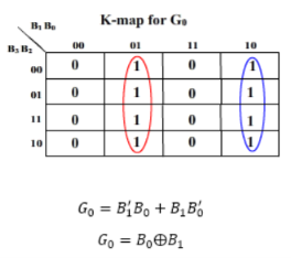
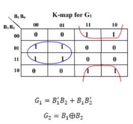
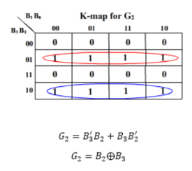
And G3 = B3
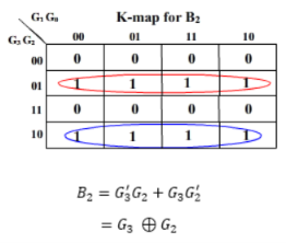
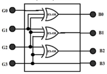
Gray to Binary Code
Then the K-maps:
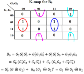
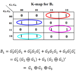
And B3 = G3
The realization of Gray-to-Binary converter is
Key Takeaways:
- These are the combinational circuits made by conversion of one code to another.
AND gate
It is a digital circuit that consists of two or more inputs and a single output which is the logical AND of all those inputs. It is represented with the symbol ‘.’.
The following is the truth table of 2-input AND gate.
A | B | Y = A.B |
0 | 0 | 0 |
0 | 1 | 0 |
1 | 0 | 0 |
1 | 1 | 1 |
Here A, B are the inputs and Y is the output of two input AND gate.
If both inputs are ‘1’, then only the output, Y is ‘1’. For remaining combinations of inputs, the output, Y is ‘0’.
The figure below shows the symbol of an AND gate, which is having two inputs A, B and one output, Y.
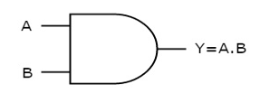
Fig: AND gate
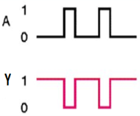
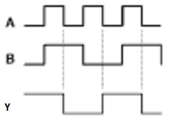
Timing Diagram:
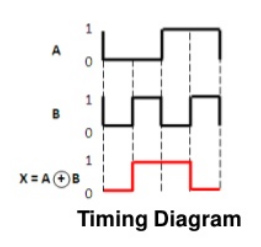
OR gate
It is a digital circuit which has two or more inputs and a single output which is the logical OR of all those inputs. It is represented with the symbol ‘+’.
The truth table of 2-input OR gate is:
A | B | Y = A + B |
0 | 0 | 0 |
0 | 1 | 1 |
1 | 0 | 1 |
1 | 1 | 1 |
Here A, B are the inputs and Y is the output of two input OR gate.
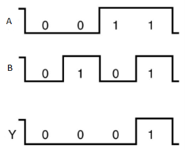
When both inputs are ‘0’, then only the output, Y is ‘0’. For remaining combinations of inputs, the output, Y is ‘1’.
The figure below shows the symbol of an OR gate, which is having two inputs A, B and one output, Y.
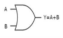
Fig.: OR gate
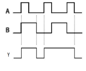
Timing Diagram:
NOT gate
It is a digital circuit that has one input and one output. Here the output is the logical inversion of input. Hence, it is also called as an inverter.
The truth table of NOT gate is:
A | Y = A’ |
0 | 1 |
1 | 0 |
Here A and Y are the corresponding input and output of NOT gate. When A is ‘0’, then, Y is ‘1’. Similarly, when, A is ‘1’, then, Y is ‘0’.
The figure below shows the symbol of NOT gate, which has one input, A and one output, Y.
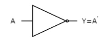
Fig: NOT gate
Timing Diagram:
Universal gates
- NAND & NOR gates are known as universal gates.
- We can implement any Boolean function by using NAND gates and NOR gates alone.
NAND gate
It is a digital circuit which has two or more inputs and single output and it is the inversion of logical AND gate.
The truth table of 2-input NAND gate is:
A | B | Y = (A.B)’ |
0 | 0 | 1 |
0 | 1 | 1 |
1 | 0 | 1 |
1 | 1 | 0 |
Here A, B are the inputs and Y is the output of two input NAND gate. When both inputs are ‘1’, then the output, Y is ‘0’. If at least one of the input is zero, then the output, Y is ‘1’. This is just the inverse of AND operation.
The image shows the symbol of NAND gate:
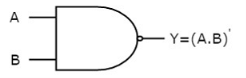
Fig.: NAND gate
NAND gate works same as AND gate followed by an inverter.
Timing Diagram:
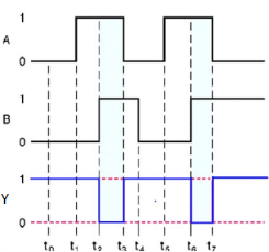
NOR gate
It is a digital circuit that has two or more inputs and a single output which is the inversion of logical OR of all inputs.
The truth table of 2-input NOR gate is:
A | B | Y = (A+B)’ |
0 | 0 | 1 |
0 | 1 | 0 |
1 | 0 | 0 |
1 | 1 | 0 |
Here A and B are the two inputs and Y is the output. If both inputs are ‘0’, then the output is ‘1’. If any one of the input is ‘1’, then the output is ‘0’. This is exactly opposite to two input OR gate operation.
The symbol of NOR gate is:
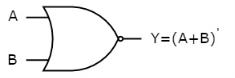
Fig.: NOR gate
NOR gate works exactly same as that of OR gate followed by an inverter.
Timing Diagram:
Special Gates
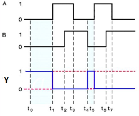
Ex-OR gate
It stands for Exclusive-OR gate. Its function varies when the inputs have even number of ones.
The truth table of 2-input Ex-OR gate is:
A | B | Y = A⊕B |
0 | 0 | 0 |
0 | 1 | 1 |
1 | 0 | 1 |
1 | 1 | 0 |
Here A, B are the inputs and Y is the output of two input Ex-OR gate. The output (Y) is zero instead of one when both the inputs are one.
Therefore, the output of Ex-OR gate is ‘1’, when only one of the two inputs is ‘1’. And it is zero, when both inputs are same.
The symbol of Ex-OR gate is as follows:
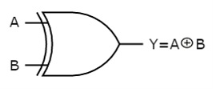
Fig.: XOR gate
It is similar to that of OR gate with an exception for few combination(s) of inputs. Hence, the output is also known as an odd function.
Timing Diagram:
Ex-NOR gate
It stands for Exclusive-NOR gate. Its function is same as that of NOR gate except when the inputs having even number of ones.
The truth table of 2-input Ex-NOR gate is:
A | B | Y = A⊙B |
0 | 0 | 1 |
0 | 1 | 0 |
1 | 0 | 0 |
1 | 1 | 1 |
Here A, B are the inputs and Y is the output. It is same as Ex-NOR gate with the only modification in the fourth row. The output is 1 instead of 0, when both the inputs are one.
Hence the output of Ex-NOR gate is ‘1’, when both inputs are same and 0, when both the inputs are different.
The symbol of Ex-NOR gate is:
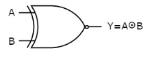
Fig.: XNOR gate
It is similar to NOR gate except for few combination(s) of inputs. Here the output is ‘1’, when even number of 1 is present at the inputs. Hence is also called as an even function.
Timing Diagram:
- Four product combinations is obtained by combining two variables x and y with logical AND operation. They are called as min terms or standard product terms. The min terms are given as x’y’, x’y, xy’ and xy.
- In the same way, four Boolean sum terms is obtained by combining two variables x and y with logical OR operation. They are called as Max terms or standard sum terms. The Max terms are given as x + y, x + y’, x’ + y and x’ + y’.
The following table represents the min terms and MAX terms for 2 variables.
x | y | Min terms | Max terms |
0 | 0 | m0=x’y’ | M0=x + y |
0 | 1 | m1=x’y | M1=x + y’ |
1 | 0 | m2=xy’ | M2=x’ + y |
1 | 1 | m3=xy | M3=x’ + y’ |
- If the binary variable is ‘0’, then it is represented as complement of variable in min term and as the variable itself in Max term.
- Similarly, if it is ‘1’, then it is represented as complement of variable in Max term and as the variable itself in min term.
- From the above table, we can easily notice that min terms and Max terms are complement of each other.
- If there are ‘n’ Boolean variables, then there will be 2n min terms and 2n Max terms.
Canonical SoP and PoS forms
- A truth table comprises of a set of inputs and output(s).
- If there are ‘n’ input variables, then there shall be 2n possible combinations comprising of zeros and ones.
- So the value of every output variable depends on the combination of input variables.
- Hence, each output variable have ‘1’ for some combination and ‘0’ for other combination of input variables.
Therefore, we can express each output variable in two ways.
- Canonical SoP form
- Canonical PoS form
Canonical SoP form
- It means Canonical Sum of Products form.
- In this, each product term contains all literals.
- So that these product terms are nothing but the min terms.
- Hence is also known as sum of min terms form.
- Firstly, identification of the min terms is done and then the logical OR of those min terms is taken in order to get the Boolean expression (function) corresponding to that output variable.
- This Boolean function will be in sum of min terms form.
- Then following the same procedure for other output variables too.
Example
Considering the following truth table.
Inputs | Output | ||
P | q | r | f |
0 | 0 | 0 | 0 |
0 | 0 | 1 | 0 |
0 | 1 | 0 | 0 |
0 | 1 | 1 | 1 |
1 | 0 | 0 | 0 |
1 | 0 | 1 | 1 |
1 | 1 | 0 | 1 |
1 | 1 | 1 | 1 |
- Here, the output (f) is ‘1’ for only four combinations of inputs.
- The corresponding min terms are given as p’qr, pq’r, pqr’, pqr.
- By doing logical OR, we get the Boolean function of output (f).
- Hence, the Boolean function of output is,
f = p’qr + pq’r + pqr’ + pqr.
- This is the desired canonical SoP form of output, f.
- It can also be represented as:
f=m3+m5+m6+m7f=m3+m5+m6+m7
f=∑m(3,5,6,7)f=∑m(3,5,6,7)
- First, we represented the function as sum of respective min terms and then, the symbol for summation of those min terms is used.
Canonical PoS form
- It means Canonical Product of Sums form.
- Here In this form, each sum term contains all literals.
- These sum terms are the Max terms.
- Hence, canonical PoS form is also known as product of Max terms form.
- Identification of the Max terms for which the output variable is zero is done and then the logical AND of those Max terms is done in order to get the Boolean expression corresponding to that output variable.
- This Boolean function is in the form of product of Max terms.
- Following the same procedure for other output variables too.
Standard SoP form
- It stands for Standard Sum of Products form.
- In this, each product term need not contain all literals.
- So, the product terms can or cannot be the min terms.
- Therefore, it is therefore the simplified form of canonical SoP form.
Standard SoP of output variable can be obtained by two steps.
- Getting the canonical SoP form of output variable
- Simplification the above Boolean function.
The same procedure is followed for other output variables too, if there is more than one output variable.
Numerical
Convert the Boolean function into Standard SoP form.
f = p’qr + pq’r + pqr’ + pqr
Solution:
Step 1 – By using the Boolean postulate, x + x = x and also writing the last term pqr two more times we get
⇒ f = p’qr + pq’r + pqr’ + pqr + pqr + pqr
Step 2 – By Using Distributive law for 1st and 4th terms, 2nd and 5th terms, 3rdand 6th terms.
⇒ f = qr(p’ + p) + pr(q’ + q) + pq(r’ + r)
Step 3 – Then Using Boolean postulate, x + x’ = 1 we get
⇒ f = qr(1) + pr(1) + pq(1)
Step 4 – hence using Boolean postulate, x.1 = x we get
⇒ f = qr + pr + pq
⇒ f = pq + qr + pr
This is the required Boolean function.
Standard PoS form
- It stands for Standard Product of Sum form.
- Here, each sum term need not contain all literals.
- So, the sum terms can or cannot be the Max terms.
- Therefore, it is the desired simplified form of canonical PoS form.
Standard PoS form of output variable is obtained by two steps.
- Getting the canonical PoS form of output variable
- Simplification of the above Boolean function.
The same procedure is followed for other output variables too.
Numerical
Convert the Boolean function into Standard PoS form.
f = (p + q + r).(p + q + r’).(p + q’ + r).(p’ + q + r)
Solution:
Step 1 – By using the Boolean postulate, x.x = x and writing the first term p+q+r two more times we get
⇒ f = (p + q + r).(p + q + r).(p + q + r).(p + q + r’).(p +q’ + r).(p’ + q + r)
Step 2 – Now by using Distributive law, x + (y.z) = (x + y).(x + z) for 1st and 4thparenthesis, 2nd and 5th parenthesis, 3rd and 6th parenthesis.
⇒ f = (p + q + rr’).(p + r + qq’).(q + r + pp’)
Step 3 − Applying Boolean postulate, x.x’=0 for simplifying of the terms present in each parenthesis.
⇒ f = (p + q + 0).(p + r + 0).(q + r + 0)
Step 4 − Using Boolean postulate, x + 0 = x we get
⇒ f = (p + q).(p + r).(q + r)
⇒ f = (p + q).(q + r).(p + r)
This is the simplified Boolean function.
Hence, both Standard SoP and Standard PoS forms are Dual to one another.
- Four product combinations is obtained by combining two variables x and y with logical AND operation. They are called as min terms or standard product terms. The min terms are given as x’y’, x’y, xy’ and xy.
- In the same way, four Boolean sum terms is obtained by combining two variables x and y with logical OR operation. They are called as Max terms or standard sum terms. The Max terms are given as x + y, x + y’, x’ + y and x’ + y’.
The following table represents the min terms and MAX terms for 2 variables.
x | y | Min terms | Max terms |
0 | 0 | m0=x’y’ | M0=x + y |
0 | 1 | m1=x’y | M1=x + y’ |
1 | 0 | m2=xy’ | M2=x’ + y |
1 | 1 | m3=xy | M3=x’ + y’ |
- If the binary variable is ‘0’, then it is represented as complement of variable in min term and as the variable itself in Max term.
- Similarly, if it is ‘1’, then it is represented as complement of variable in Max term and as the variable itself in min term.
- From the above table, we can easily notice that min terms and Max terms are complement of each other.
- If there are ‘n’ Boolean variables, then there will be 2n min terms and 2n Max terms.
Karnaugh map method or K-map method is the pictorial representation of the Boolean equations and Boolean manipulations are used to reduce the complexity in solving them. These can be considered as a special or extended version of the ‘Truth table’.
Karnaugh map can be explained as “An array containing 2k cells in a grid like format, where k is the number of variables in the Boolean expression that is to be reduced or optimized”. As it is evaluated from the truth table method, each cell in the K-map will represent a single row of the truth table and a cell is represented by a square.
The cells in the k-map are arranged in such a way that there are conjunctions, which differ in a single variable, are assigned in adjacent rows. The K-map method supports the elimination of potential race conditions and permits the rapid identification.
By using Karnaugh map technique, we can reduce the Boolean expression containing any number of variables, such as 2-variable Boolean expression, 3-variable Boolean expression, 4-variable Boolean expression and even 7-variable Boolean expressions, which are complex to solve by using regular Boolean theorems and laws.
Minimization with Karnaugh Maps and advantages of K-map:
- K-maps are used to convert the truth table of a Boolean equation into minimized SOP form.
- Easy and simple basic rules for the simplification.
- The K-map method is faster and more efficient than other simplification techniques of Boolean algebra.
- All rows in the K-map are represented by using square shaped cells, in which each square in that will represent a minterms.
- It is easy to convert a truth table to k-map and k-map to Sum of Products form equation.
There are 2 forms in converting a Boolean equation into K-map:
- Un-optimized form: It involves in converting the number of 1’s into equal number of product terms (min terms) in an SOP equation.
- Optimized form: It involves in reducing the number of min terms in the SOP equation.
Grouping of K-map variables
- There are some rules to follow while we are grouping the variables in K-maps. They are
- The square that contains ‘1’ should be taken in simplifying, at least once.
- The square that contains ‘1’ can be considered as many times as the grouping is possible with it.
- Group shouldn’t include any zeros (0).
- A group should be the as large as possible.
- Groups can be horizontal or vertical. Grouping of variables in diagonal manner is not allowed.
- If the square containing ‘1’ has no possibility to be placed in a group, then it should be added to the final expression.
- Groups can overlap.
- The number of squares in a group must be equal to powers of 2, such as 1, 2, 4, 8 etc.
- Groups can wrap around. As the K-map is considered as spherical or folded, the squares at the corners (which are at the end of the column or row) should be considered as they adjacent squares.
- The grouping of K-map variables can be done in many ways, so they obtained simplified equation need not to be unique always.
- The Boolean equation must be in must be in canonical form, in order to draw a K-map.
2 variable K-maps
There are 4 cells (22) in the 2-variable k-map. It will look like (see below image)
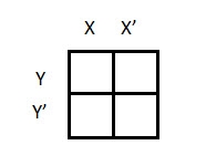
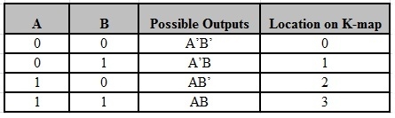
The possible min terms with 2 variables (A and B) are A.B, A.B’, A’. B and A’. B’. The conjunctions of the variables (A, B) and (A’, B) are represented in the cells of the top row and (A, B’) and (A’, B’) in cells of the bottom row. The following table shows the positions of all the possible outputs of 2-variable Boolean function on a K-map.
A general representation of a 2 variable K-map plot is shown below.
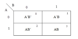
When we are simplifying a Boolean equation using Karnaugh map, we represent each cell of K-map containing the conjunction term with 1. After that, we group the adjacent cells with possible sizes as 2 or 4. In case of larger k-maps, we can group the variables in larger sizes like 8 or 16.
The groups of variables should be in rectangular shape that means the groups must be formed by combining adjacent cells either vertically or horizontally. Diagonal shaped or L-shaped groups are not allowed. The following example demonstrates a K-map simplification of a 2-variable Boolean equation.
Example
Simplify the given 2-variable Boolean equation by using K-map.
F = X Y’ + X’ Y + X’Y’
First, let’s construct the truth table for the given equation,
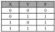
We put 1 at the output terms given in equation.
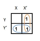
In this K-map, we can create 2 groups by following the rules for grouping, one is by combining (X’, Y) and (X’, Y’) terms and the other is by combining (X, Y’) and (X’, Y’) terms. Here the lower right cell is used in both groups.
After grouping the variables, the next step is determining the minimized expression.
By reducing each group, we obtain a conjunction of the minimized expression such as by taking out the common terms from two groups, i.e., X’ and Y’. So, the reduced equation will be X’ +Y’.
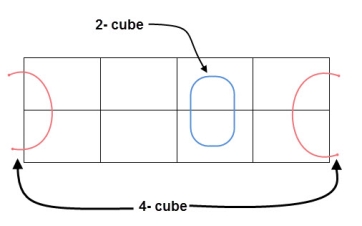
3 variable K-maps
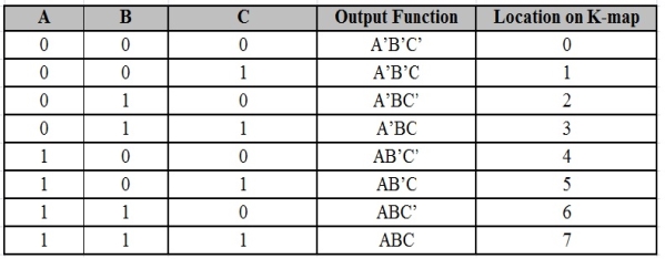
For a 3-variable Boolean function, there is a possibility of 8 output min terms. The general representation of all the min terms using 3-variables is shown below.
A typical plot of a 3-variable K-map is shown below. It can be observed that the positions of columns 10 and 11 are interchanged so that there is only change in one variable across adjacent cells. This modification will allow in minimizing the logic.
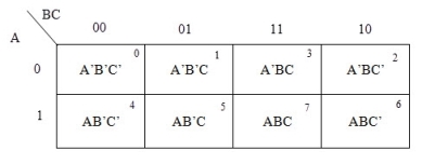
Up to 8 cells can be grouped in case of a 3-variable K-map with other possibilities being 1, 2 and 4.
Example
Simplify the given 3-variable Boolean equation by using k-map.
F = X’ Y Z + X’ Y’ Z + X Y Z’ + X’ Y’ Z’ + X Y Z + X Y’ Z’
First, let’s construct the truth table for the given equation,
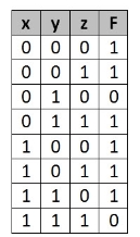
We put 1 at the output terms given in equation.
There are 8 cells (23) in the 3-variable k-map. It will look like (see below image).
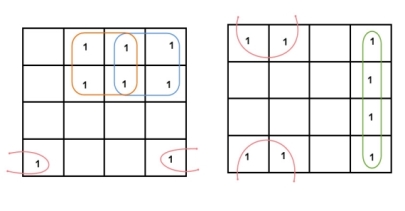
The largest group size will be 8 but we can also form the groups of size 4 and size 2, by possibility. In the 3 variable Karnaugh map, we consider the left most column of the k-map as the adjacent column of rightmost column. So, the size 4 group is formed as shown below.
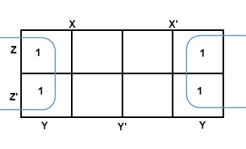
And in both the terms, we have ‘Y’ in common. So, the group of size 4 is reduced as the conjunction Y. To consume every cell which has 1 in it, we group the rest of cells to form size 2 group, as shown below.
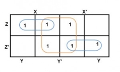
The 2-size group has no common variables, so they are written with their variables and its conjugates. So, the reduced equation will be X Z’ + Y’ + X’ Z. In this equation, no further minimization is possible.
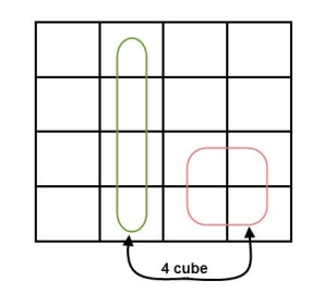
4 variable K-maps
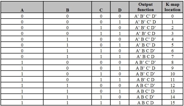
There are 16 possible min terms in case of a 4-variable Boolean function. The general representation of minterms using 4 variables is shown below.
A typical 4-variable K-map plot is shown below. It can be observed that both the columns and rows of 10 and 11 are interchanged.

The possible numbers of cells that can be grouped together are 1, 2, 4, 8 and 16.
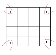
Example
Simplify the given 4-variable Boolean equation by using k-map. F (W, X, Y, Z) = (1, 5, 12, 13)
Sol: F (W, X, Y, Z) = (1, 5, 12, 13)
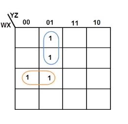
By preparing k-map, we can minimize the given Boolean equation as
F = W Y’ Z + W ‘Y’ Z
References:
1. Modern digital Electronics- R. P. Jain, McGraw Hill.
2. Digital Integrated Electronics- Herbert Taub, McGraw Hill.
3. Digital Logic and Computer Design- Morris Mano (PHI).
4. Digital Integrated Electronics- Herbert Taub, McGraw Hill.
5. Digital Electronics Logic and System – James Bingnell and Robert Donovan, Cengage Learning.


