UNIT 5
Satellites
Satellite Subsystems are required on a spacecraft with details of Telemetry, Tracking and Command System. TTC&M refers to Telemetry Monitoring and Command subsystem. These subsystem are established on the earth. The telemetry and command subsystem provides us the information about the happenings going on with the satellites on the space.
Satellite Subsystems
A complete satellite consists of several subsystems, but the most important of them are as follow:
- Power Supply System.
- Attitude and Orbit Control System.
- Telemetry, Tracking and Command System.
- Communication Subsystem.
Telemetry, Tracking and Command System

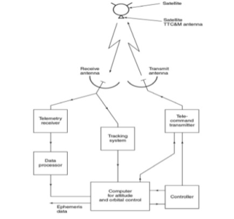
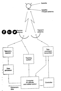
Typical Telemetry, Tracking, Command and Monitoring System.
It collects data from many sensors within the satellite and send these data to the controlling earth station.
Several hundred of sensors are located on satellite to monitor pressure in fuel tanks , voltage and current in power conditioning unit, current drawn by each subsystem and critical voltages and current in communications electronics.
Temperature of many subsystems must be kept within predetermined limits so many temperature sensors are fitted.
The sensor data the status of each subsystem are reported back to the earth by telemetry system.
Telemetry data are digitized and transmitted as PSK of low power telemetry carrier using time division techniques.
At controlling earth station a computer can be used to monitor , store and decode telemetry data so that status of any system or sensors on the satellite can be determined immediately.
Alarms can also be sounded if any vital parameter goes outside allowable limits.
Tracking:
- A number of techniques can e used to determine current orbit of satellite.
- Velocity and acceleration sensors on satellite can be used to establish the change in orbit from last known position by integration of data.
- The earth station controlling satellite can observe the Doppler shift of telemetry carrier to determine rate at which range is changing.
- Active determination of range can be achieved by transmitting a pulse or sequence of pulses to satellite and observing time delay before pulse is received again.
Command
- The command system is used to make changes in attitude and corrections to the orbit and to control communication system.
- During launch, it is used to control firing of AKM and to spin up spinner or extended solar sails and antennas of 3–axis stabilized satellite.
- The command structure must possess safeguards against unauthorized attempts to make changes to satellite’s operation.
- Encryption of commands and responses are used to provide security in command system.
- After monitoring all the data commands are generated at the control terminal of computer.
- The command word is sent in a TDM frame to the satellite
- After checking for validity in satellite command word is sent back to the control station via telemetry link where it is checked again in the computer.
- If found correctly an execute instruction will be sent to the satellite.
- The entire process may take 5 or 10s but minimizes the risk of erroneous commands causing satellite malfunction.
Power System:
- All communication satellites obtain their electrical power from solar cells which converts incident light into electrical energy.
- Some deep space planetary research satellites have used thermonuclear generators.
- Communication satellite have not used nuclear generators.
- Sun is a powerful source of energy.
- At geostationary attitude the radiation falling on a satellite has an intensity of 1.39 kW/m2.
- Solar cells do not convert all incident energy into electrical power.
- Since sufficient power must be available at the end of life of satellite to supply all the systems on board.
- A spin-stabilized satellite usually has a cylindrical body covered in solar cells.
- Because, solar cells are on the cylindrical surface , half of the cells are not illuminated at all which results in little electrical power being generated.
- The cells that are not illuminated by sunlight face cold space which causes them to cool down.
- Large communication satellites for direct broadcast operation generate up to 6KW from solar power.
- This subsystem consists of rocket motors that are used to move the satellite back to the correct orbit when external forces cause it to drift off station.
- Gas jets are used to control the attitude of the satellite.
- The attitude and orbit of the satellite must be controlled so that the satellite’s antenna point toward the earth so that the user knows where to look for satellite in the sky.
Attitude control system
- Two ways can make the satellite stable in the orbit.
- The orbit of the satellite can be rotated at rate between 30 and 100 rpm , that provides stability of the spin axis and keeps it pointing in the same direction which are known as spinners.
- Alternative way of satellite stability is by one or more momentum wheels called as three-axis stabilized satellite.
- The momentum wheel is usually a solid metal disk driven by an electric motor.
- There must be one momentum wheel for each of the three axes of the satellite and rotated to provide a rotational force about any of the three axes.
- There are two types of rocket motors used on satellite:
- Bipropellant thrusters
- Arc jets or ion thrusters.
- In three-axis stabilized satellite one pair of gas jets is needed for each axis to provide rotation in both direction.
- When motion required along particular axis the appropriate jets is operated for a specific period of time.
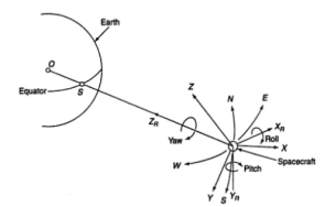
- The satellite attitude is defined in terms three axis- ROLL,PITCH,YAW
- Roll axis is towards the velocity vector of the satellite moves in orbit.
- Yaw axis is towards the earth center.
- Pitch axis is mutually perpendicular to both these two axis.
- They are called the earth oriented co-ordinate axis.
- Any perturbing force about a particular axis can cause a slight rotation about that axis.
- The zero error attitude is defined when the satellite antenna radiation beam point to the required direction.
- With this zero error attitude, the solar panels also will be able to track the sun properly.
- The error in attitude is determined by attitude error detection sensors (infra red earth sensors) attached to the satellite.
- Any object which is above absolute zero degree Kelvin radiates energy and earth at 300 degree Kelvin radiates infrared energy more compared to other wavelength bands.
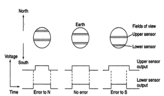
Principle of N-S control of a spinner satellite using Infrared earth sensors
By processing the pulse width generated by sensors it is possible to measure the attitude error about Roll and pitch axes.
Orbit Control
- The gravitation forces of moon and the sun cause inclination of orbital plane.
- There are many other smaller forces that act on satellite causing orbit to change.
- For the orbit to be geostationary it must lie in equatorial plane be circular and have correct altitude.
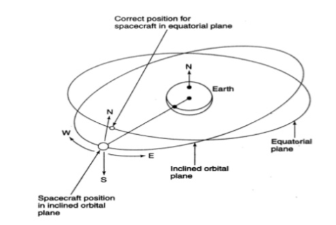
- The various forces acting on the satellite will steadily pull it out of the correct orbit ; the function of orbit control system is to return it to the correct orbit.
- Gas jets are can impart velocity changes along three reference axes
- Correcting the inclination of the satellite orbit requires more fuel to be expended than for any other orbital correction.
- This places a weight penalty on those satellites that maintain accurate stations keeping and reduces communication payload they can carry.
Attitude system design is an iterative process.
Figure a presents all the processes involved in attitude systems. The FireSat II spacecraft, shown in Figure b and the Supplemental Communications System (SCS) constellation of spacecraft, shown in Figure c will be used to illustrate this process.
- TTC&M subsystems are located partly on satellite and partly on earth station.
- The telemetry link sends the data about satellite’s health to the earth station.
- At the ground station the tracking system provides the information about the range, azimuth and elevation angles of the satellite.
- By repeated measurement of these data, the changes in the orbit can be optimized.
- The telemetry data from satellite and orbital data from earth station are used to correct the position and attitude of the satellite and also to control the antenna pointing and communication system configuration.
- Large no. Of sensors located within the satellite sends data to the controlled computer at the earth station used to monitor, store and decode the telemetry data.
- The sensors usually monitor pressure in the fuel tanks, voltage and current in the power conditioning unit, current drawn by each subsystem, critical voltages and currents in the communication circuits, temperature rise in different subsystems.
- Telemetry system used during the launching and also when the satellite in GEO orbit, a highly directive antenna and PSK modulated and TDM multiplex digital data are sent to the earth station.
- Low data rate used such that the receiver bandwidth is a narrow bandwidth and high carrier to noise ration.
- Tracking system in the TTC&M subsystem is used to determine the satellite’s orbit during launching and then to track the satellite. It determines the current orbit of a satellite.
- Various techniques for tracking of a satellite.
- Velocity and acceleration sensors on the satellites can be used to establish the change in orbit. Doppler shift of the telemetry carrier from the earth station or beacon transmitter may be measured to determine the rate at which the range is changing. Ranging tones may be used for measurement.
- Active determination can be achieved by sending pulse or sequence of pulses and measure their delay at the earth station.
- Triangular methods may be apply when sufficient no of earth station are observing, which can precisely determine the position accurately even within 10 meters.
- Command system is used to make changes in attitude and corrections to the orbit and to control the communication system.
- It is also used to spin-stabilized satellite and also to extend the solar sails and antennas of a three axis stabilized satellite.
- Encrypted command and responses used to provide security sends from the controlled computer of the TTC&M system.
- Usually earth-coverage horn antennas are used as TTC & M antenna in the 6/4 GHz system.
- A back-up TTC&M system is used during the launching and injection into the geo-stationary orbit of the satellite, which control the apogee kick motor, the attitude control system and orbit control thrusters, the solar sail deployment mechanism and the power conditioning unit.
- The back-up system is used to keep the satellite on station in the event of failure of the main TTC & M system. It is also used to eject the satellite from GEO orbit and to switch off all transmitters when the satellite reaches the end of life.
Power system is a vital subsystem, which provides the power required for working of a satellite. Mainly, the solar cells (or panels) and rechargeable batteries are used in these systems.
Solar Cells
Basically, the solar cells produce electrical power (current) from incident sunlight. Therefore, solar cells are primarily used to provide power to other subsystems of satellite.
We know that individual solar cells generate very less power. So, in order to generate more power, group of cells that are present in an array form are used.
Solar Arrays
There are two types of solar arrays that are used in satellites. Those are cylindrical solar arrays and rectangular solar arrays or solar sail.
- Cylindrical solar arrays are used in spinning satellites. Only part of the cylindrical array will be covered under sunshine at any given time. Due to this, electric power gets generated from the partial solar array. This is the drawback of this type.
- The drawback of cylindrical solar arrays is overcome with solar sail. This one produces more power because all solar cells of solar sail are exposed to sun light.
Rechargeable Batteries
During eclipses time, it is difficult to get the power from sun light. So, in that situation the other subsystems get the power from rechargeable batteries. These batteries produce power to other subsystems during launching of satellite also.
In general, these batteries charge due to excess current, generated by solar cells in the presence of sun light.
A transponder consists of BPF to select particular band of frequency a down converter and an output amplifier.
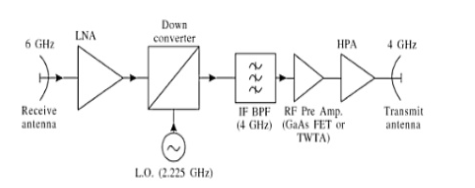
- Figure shows a typical single conversion bent pipe transponder used on many satellites for 6/4 GHz band.
- The local oscillator is at 2225MHz to provide the appropriate shift in frequency from 6GHz to 4GHz.
- Band pass filter after the mixer removes unwanted frequencies.
- The output power amplifier is usually a solid state power amplifier (SSPA) unless a very high output power is required.
The different types of satellite antennas are :
- Wire antennas: Monopole and Dipole.
- Horn Antennas
- Reflector Antennas
- Array Antennas
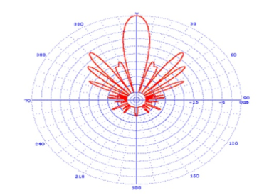
Wire Antennas:
- These are used primarily at VHF and UHF to provide communications for the TTC and M systems.
- They are positioned with great care on the body satellite in an attempt to provide omnidirectional coverage.
- An antenna pattern is a plot of the field strength in far field on antenna.
- It is usually measured in decibels.
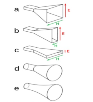
Horn Antennas:
- These are used at microwave frequencies when relatively wide beams are required for global coverage.
- A horn is flared section of waveguide that an aperture wavelengths wide and good match between the waveguide impedance and free space.
- Horns are used as feeds for reflectors.
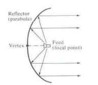
Reflector Antennas:
The most often used antenna for satellite systems particularly for those operating above 10GHz is the parabolic reflector antenna.
These are usually illuminated by one or more horns and provide a larger aperture compared to horn antenna.
Parabolic reflectors offer higher gain than that achievable by the horn antenna alone.
Array Antennas:
Array antennas are used on satellites to create multiple beams from a single aperture.
Multiple beams are formed by combining the radiation from several small elements made up of dipoles, horns etc.
Iridium and Global star used these kind of antennas to generate up to 16 beams from a single aperture for their LEO mobile telephone systems.
- Once the satellite is in geostationary orbit there is little possibility of repairing components that fail or adding more fuel for station keeping.
- The component that makes up the satellite must therefore have high reliability.
- Two approaches are used : Space qualification of every part of the satellite to ensure that it has long life expectancy in orbit and redundancy of most critical components to provide continued operation when component tool fails.
Space Qualification
- Outer space at geostationary orbit distances is a harsh environment.
- The sun irradiates the satellite with 1.4kW of heat and light on each square meter of exposed surface.
- When surfaces are in shadow surface temperature will fall toward absolute zero.
- Electronic equipment can’t operate at such extremes of temperature and heated or cooled so that its temperature stays within the range 0 o to 75 0 C . This requires a thermal control system.
- The first stage in ensuring high reliability in a satellite is by selection and screening of every component used.
- Past operational and test experience of components indicates which components can be expected to have good reliability.
- Each component is tested individually to ensure that it meets its specification . This process is known as quality control or quality assurance and is vital in building any equipment that is to be reliable.
- Once individual components and subsystems have been space qualified the complete satellite must be tested as a system to ensure that its many systems are reliable.
- When a satellite is designed three prototype models are often build and tested.
References:
- Optical Fiber Communications: Principles and Practice John M Senior
- Optical Fiber Communications by Gerd Keiser


