Unit 4
D. C. Machines (Part-2)
The characteristic curve of DC Motor can be described by the below mentioned relationships
a) Torque and Armature Current (Electrical characteristics)
b) Speed and Armature Current
c) Speed and Torque (Mechanical characteristics)
Now briefly describing the above mentioned characteristics for DC Series Motor
4.1.1 Characteristics for DC Series Motor
a) Torque and Armature current characteristics: As we have already seen that armature torque Ta is proportional to the product of flux linked and the armature current
Ta α φ Ia
Since φ α Ia
Ta= I2a
As Ta is proportional to the square of armature current, the curve is Parabolic as shown below.
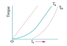
Fig. 1: T v/s Ia characteristics
b) Speed and armature current characteristics: As we know speed (N) is related to back emf as
N α Eb/φ
But φ α Ia .
So, as the value of Ia increases the vale corresponding value of φ also increases. So, N αEb/ Ia
As the speed increases the value of current decreases (inversely proportional). For various values of load current there is very small change in the value of Eb, hence can be neglected here. The curve is shown below.
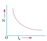
Fig. 2: Speed verses Armature current characteristics
c) Speed and Torque characteristics: As Ta α φ Ia and φ α Ia , but N αEb/ Ia .So it can be easily concluded that speed and torque are inversely proportional. Hence when speed is high torque is low and vice versa. The curve is shown below.
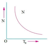
Fig 3: Speed verses Torque characteristics
Key takeaway
For speed torque characteristics Ta α φ Ia and φ α Ia, but N αEb/ Ia
For speed armature characteristics N α Eb/φ but φ α Ia.
For Torque armature characteristics Ta= I2a
4.1.2 Characteristics of DC Shunt Motor
a) Torque and Armature current characteristics: As relation between torque and armature current is Ta α φ Ia , assuming φ to be practically constant. So, Ta α Ia and the characteristics are linear as shown below.
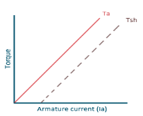
Fig. 4: Torque versus Armature current
b) Speed and Armature current characteristics: N α Eb/φ , for φ to be practically constant N α Eb . But both Eb and φ decrease with increasing load. The drop varies from 5 to 15% of full load speed. As Eb decreases more than φ speed decreases.
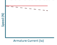
Fig. 5: Speed verses Armature current characteristics
c)Speed and Torque Characteristics: From above to characteristics, curve for this shown below.
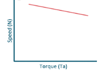
Fig. 6: Speed verses Torque characteristics
Key takeaway
Torque armature characteristics are linear
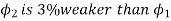
Que) A 250V shunt motor on no load runs at 900rpm and takes 4amperes, armature and shunt field resistances are 0.2 and 250 ohms respectively. Calculate the speed when loaded taking current of 50A. The armature reactions weakens the field by 3%?
Sol: Ish=250/250=1A
Ia1=4-1=3A
Ia2=50-1=49A
Eb1=250-3*0.4=248.8V
Eb2=250-49*0.2=240.2A
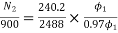
N2=898rpm
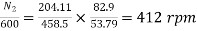
Que) The speed of a 37.3kW series motor working on 500V supply is 600 rpm at full load and 90% efficiency. If the load torque is made 250 N-m and a 5ohm resistance is connected in series with the machine, calculate the speed at which the machine will run. Assume armature and field resistance of 0.5ohm?
Sol: Load torque in first case T1=37300/2 (600/60) = 593.65 N-m
Input current Ia1=37300/0.9*500=82.9A
T2=250 N-m. So, finding Ia2
For series motor T α φ Ia α Ia2
T1 α  and T2 α

 = 82.9*
 = 53.79A
Eb1 = 500-(82.9*0.5) = 458.5V
Eb2 = 500-53.79(5+0.5) = 204.11V

Series Motor: They are used in Electric locomotives, Cranes, Hoists, Conveyors and cars.
Shunt Motor: They are used for Blowers, Fans, centrifugal pumps, for driving constant speed line shafting lathes.
All motors should be started with external resistance in armature circuit to limit the starting current to safe values, if not then there can be a risk of high value of torque which can cause mechanical shock to the shaft and it can also cause heavy sparking at the brushes which can damage the commutator and brush gear. At the time of starting the induced emf of motor is zero. In case of direct start of motor, the toque is much higher and motor starts quickly, which saves the energy and reduces temperature rise. Maximum allowable starting current cannot be more than 1.5 to 2.0 times the rated value. For variable speed the starting of motor has no problem.
The connection diagram of DC Shunt motor starter is shown below. It is the manual starter.
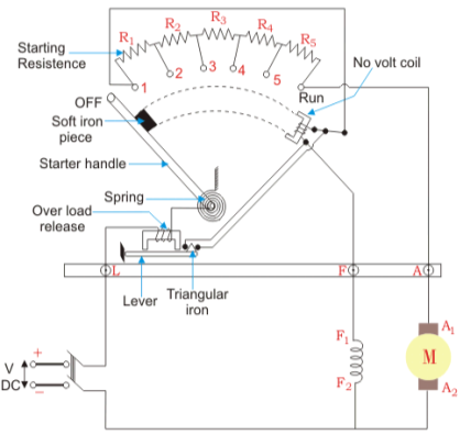
Fig. 7: DC Shunt motor starter
In shunt motor starting to maintain high torque the starting resistance is arranged in steps. When starter is in ON position the starting resistance is cut out. The handle can go back to OFF position when there is no field current and in case of overload when the contact of relay at armature current is above certain value. Modern industries use push button type automatic starters. As shown in the figure below
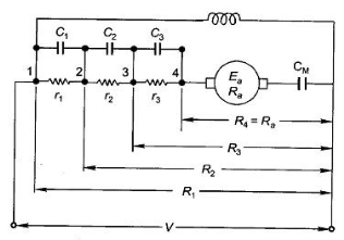
Fig. 8: Shunt motor starting
They have automatic relays that short the section of starting resistors when the armature current has dropped to a pre-set value.
Calculation of starter step for DC Shunt Motor
From above figure when the stud is moved to point 1, the current I1 is reached.
I1 = V/R1
When the speed of motor increases the current decreases and the back emf rises. The value of current I2 is given as
I2=
 is back emf. The current I1 is given as
I1=

For k stud starter


Hence

After calculating starter step
i)Find R1
Ii)Find number of steps k
Iii)Find R1, R2…….
Key takeaway
At the time of starting the induced emf of motor is zero. In case of direct start of motor, the toque is much higher and motor starts quickly, which saves the energy and reduces temperature rise.
Que) A starter required for a 220V shunt motor. The maximum allowable current is 45A and the maximum current is about 35A. Find the number of sections of starter resistance required and the resistance of each section. The armature resistance of motor is 0.4 ohm?
Sol: I1=45 A, I2=35 A
 =1.28
=1.28
R1= Ω
Ω
As 
 =
= =11.1
=11.1


As we already know 
R1=4.44Ω
R2=
R3=
r1= R1- R2=2.01
r2= R2- R3=1.1
Similarly, r3=0.60 , r4=0.20
 can be calculated.
Basically, there are three types of starters
i) Two-point starter
Ii) Three-point starter
Iii) Four-point starter
For series motor:
Basically a 2-point starter is used in DC series motor. As we already know that Eb is given as
Eb=  where Ia =Armature current and V =Terminal voltage
V-Eb=IaRa
When Eb=0. From above equation Ia at the moment of starting can be given as Ia= V/Ra.
The Ra is very low in practically, generally about 0.3 to 0.8 ohms. Therefore, a large current flow through the armature during starting. This current is large enough to damage the armature circuit. This also causes blowing of fuse and dip in terminal voltage of other equipment connected locally. This is the main reason why starters are used in DC motors.


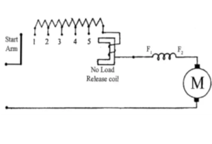
Fig. 9: Two-point starter
When the starter arm is moved to 1, it gets attached to maximum resistance connected in series with armature during starting, and decreases gradually as it moves towards right. A DC series motor must always be started on load. If started on No load the motor will attain a dangerously high speed.
For Shunt motor:
A 3-point starter is used for starting a DC shunt motor. The starter is shown below
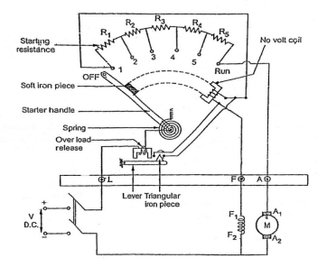
Fig. 10: 3-point starter
The arm of stud is moved to 1, to start the motor. The complete resistance added to armature winding. Through No-volt-coil(NVC) the field winding also gets full supply. So, the motor develops torque and starts rotating with full starting resistance. When the stud is moved further RUN position is achieved. In this position a soft iron piece is attached to starter arm. Therefore, will stay in the RUN position against the spring tension. In case of overload the armature winding will draw excess current and may get damaged. So, to protect from this damage the over load release coil will be short circuited and will demagnetise NVC. Which will eventually turn off DC motor.
Disadvantages of 3-point starter:
The field current is reduced when a large resistance is connected to increase the speed. But the field winding and NVC are connected in series, the current through NVC decreases. This may cause the starter to move to OFF position, which may affect the working of motor. To overcome this drawback, we have four-point starter.
Four-point starter:
In this the NVC coil is connected independently across the supply voltage instead of connecting it in series with the motor field winding.
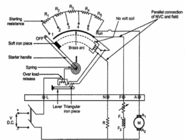
Fig. 11: Four Point starter
When the arm is brought to position 1 current flows through armature winding, the field winding will also get full supply. In this the field winding and NVC are isolated from each other. Hence, any change in If will not affect NVC like in three-point starter. When started arm is brought to the RUN position, the armature of the dc motor will run at its full speed and remain connected to the supply through the starter arm. In case of overload, the OLR terminal will be short circuited to the NVR coil to release the starter arm to the OFF position.
Key takeaway
The field current is reduced when a large resistance is connected to increase the speed. But the field winding and NVC are connected in series, the current through NVC decreases. This may cause the starter to move to OFF position, which may affect the working of motor.
The solid-state motor starter uses triacs and transistors for power control in AC motor starters, and SCRs and transistors for DC motor starters. These starters are the combination of solid-state circuitry. Some have six potentiometers mounted on the starter. These potentiometers help to set up the ramp up and ramp down functions of motor. This is called as soft starting. The traditional starters provide full voltage to the starter the moment the coil is energised. But these solid-state starters help to increase voltage slowly and allowing the soft start of motor and attaining full speed. They also provide adjustable overloads.
The speed control of DC motor is given by
N= rpm
rpm
The speed can be controlled by varying
i)Φ=flux/pole
Ii)Ra=Armature resistance
Iii)V=Applied voltage
For DC Series Motor: In DC Series motor speed control can be done in two ways:
i)Flux Control: In this there are four ways to control speed
a) Field Divertors
b) Armature Divertors
c) Trapped Field control field
d)Paralleling field coils
Ii) Variable resistance in series with motor
Firstly, discussing the Flux Control method to control speed in DC Series motor.
a) Field Divertors: In this one variable resistance in parallel to the field winding is connected. It is called as field divertor. We can control the current through the field divertor by adjusting its resistance. As we can control the current, the flux can also be decreased and hence the speed will increase. Below shows the figure.
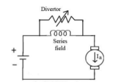
Fig. 12: Field Divertor
b) Armature Divertor: In this the variation in speed can be controlled by varying the divertor resistance. As we know TaαφIa and Nα . Hence if flux increases (as Ia can be reduced due to armature divertor) speed will decrease. The figure is shown below.
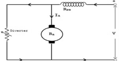
Fig. 13: Armature Divertor
c)Trapped Field control field: In this the series field turns can be changed according to our wish. The speed can be increased by removing off some of the series turns. The figure is shown below.
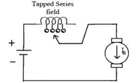
Fig. 14: Trapped Field control field
d) Paralleling field coils: In this speed control can be done by regrouping the field coils.
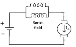
Fig. 15: Paralleling of field coils
Ii) Variable resistance in series with motor: The voltage across armature can be reduced increasing the resistance in series with it. As the voltage reduces the speed also reduces. The below fig a shows the variable resistance across armature and fig b shows the variation of speed with respect to armature current.
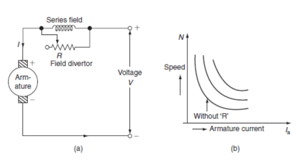
Fig. 16: Circuit and characteristics of variable resistance in series with motor
For DC Shunt Motor: There are three basic methods to control the speed of DC Shunt motor listed below
i)Flux control method
Ii)Armature or Rheostatic control
Iii)Voltage control
i) Flux control method: As we already know that flux and speed for shunt motors are inversely proportional to each other. As the name suggests flux control which means we can control the flux and maintain required speed. The flux can be controlled by changing Ishwith help of shunt field rheostat. The figure is shown below.
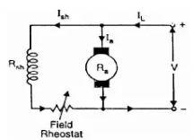
Fig 17: Flux control method
Ii) Armature or Rheostatic control: This is the most common method employed. In this the controlling resistance is connected directly in series with the supply of the motor. As resistance Ra is increased potential drop across armature decreases, and hence the speed too decreases. The figure is shown below.
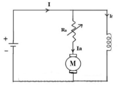
Fig. 18: Armature control
One more to control speed here is shunting the armature and a rheostat in series with the armature is involved in this method of speed control. The voltage applied to the armature varies by varying series rheostat R1. The exciting current can be varied by varying the armature shunting resistance R2. This method of speed control is not economical due to considerable power losses in speed controlling resistances.
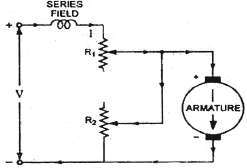
Fig. 19: shunted armature speed control
Iii) Voltage control method: There are two ways in voltage control method
a) Multiple voltage control: In this method the shunt field of motor is connected permanently to a fixed exciting voltage, but armature is supplied with different voltages. The armature speed is approximately proportional to these different voltages. This method is not used now.
b) Ward-Leonard System: The figure below shows the ward-Leonard system. In this method speed of motor M1is controlled which is powered by generator G. The shunt field of motor is connected across DC supply. The motor M2derives the generator. When the output voltage of the generator is fed to the motor M1 then the motor starts to rotate. When the output voltage of the generator varies then the speed of the motor also varies. By controlling the output voltage of generator speed of motor can be controlled. To attain this a field regulator is connected across the generator. The direction of rotation of motor can be reversed by excitation current of generator, this will happen by reversing the switch R.S. The motor-generator should run in same direction.
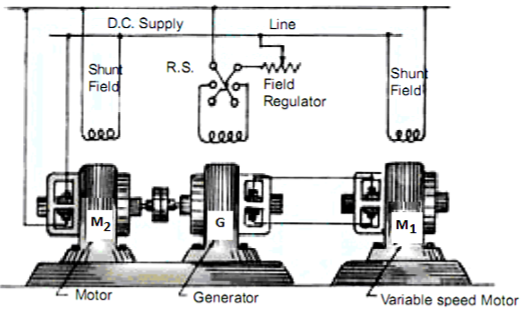
Fig. 20: Ward Leonard System
Key takeaway
The speed can be controlled by varying
i)Φ=flux/pole
Ii)Ra=Armature resistance
Iii)V=Applied voltage
Que) A dc series motor drives a load torque of which varies as the square of the speed. The motor takes a current of 15A when speed is 500 rpm. Calculate the speed and the current when the motor field winding is shunted by a diverter of same resistance as that of the field winding.
Sol: As we already know TaαφIa and Nα
Ta1 α 
Ta2 α 

Ta1 α φ1Ia1
Ta2 α φ2Ia2
As field current is half the armature current so 
 ………(1)

Neglecting armature and series winding drop.
 ………(2)
From 1 and 2


 =
= 152=25.2A
From 2 we get N2=500*2*15/25.2=595.2 rpm
Que) A 200V dc shunt motor running at 900rpm takes an armature current of 15.5A. It is required to reduce the speed to 600 rpm. What must be the value of resistance to be inserted in the armature circuit if the original resistance is0.4Ω?
Sol:N1=900rpm
Eb1=200-15.5*0.4=193.8 V
N2=600rpm
Eb2=200-15.5*Rt
Rt= total armature circuit resistance
Assuming armature current constant. Φ1= Φ2
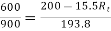
Rt=4.57 Ω
Additional resistance required=Rt-Ra=4.57-0.4=4.17 Ω
Basically, commutation means reversal of current in DC machines. In DC motors commutation is used to reverse the directions of DC current before being applied to the coils of the motor. The device used for commutation is called as commutator. The basic principle on which a motor works is electromagnetic induction. When current is passed through a conductor it produces magnetic field lines around it.
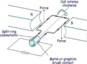
Fig. 21: Motor effect
The conductor having magnetic field induced around it when placed in the path of magnetic lines of forces, they block the path. To remove this obstacle the lines of forces move either up or down according to the current direction. This gives rise to motor effect. Now if electromagnetic coil is placed between two magnets with opposite poles facing each other, the magnetic lines move the coil up when current is in one direction and down when current in opposite direction. This develops rotatory motion in coil. To change the direction of current in the coil, two half-moon shaped metals are attached to each end of the coil called Commutator. Metal brushes are placed with one end attached to the battery and the other end connected to the commutators.
Commutation in DC Machine
The armature coil has two commutators connected to its ends. When commutators and brushes are in contact current transformation can be attained. In DC machines we use more than one coil. As shown in below figure.
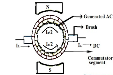
Fig. 22: Commutation
Hence, we have more than one pair of commutator segments. The coil is short-circuited for a very short period of time with the help of brushes. This period is known as commutation period.
Reactance voltage: The coil in armature slot has self-inductance L. As we already know the direction of current is reversed in commutation. So, due to reversal of current and self-inductance a voltage is induced equal to  . This voltage is also known as Reactance voltage.
Reactance voltage=
Tc= Commutation period.
I is maximum change in current in either direction.
So total change in current = I-(-I)=2I
Reactance voltage=
1.11 is form factor of sinusoidal waveform.
Time of commutation: covered in section 4.10
Key takeaway
Commutation means reversal of current in DC machines. In DC motors commutation is used to reverse the directions of DC current before being applied to the coils of the motor.
4.8.1 Straight line commutation
This type of commutation is also called as Ideal commutation. In this type of commutation, the current from commutating coil changes linearly from +Ic to -Ic. The below figure shows the same.
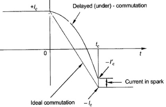
Fig. 23: Ideal Commutation
There are two ways of achieving good commutation—close to straight-line commutation. These are resistance commutation and voltage commutation.
4.8.2 Under and Over Commutation
As we have already discussed about commutation. Here we will deeply study how the commutation occurs in Dc machines. Considering a DC motor having width of commutator bars same as width of brushes. The current flowing through conductor be Ia. Let a, b, c be the commutator segments of motor. Now we will see how the current reversal takes place in the coil.
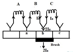
Fig. 24: Position 1
Let the first position of the brush commutator contact be at segment b. As the width of the commutator is equal to the width of the brush, in the above position the total areas of commutator and brush are in contact with each other. The total current conducted by the commutator segment into the brush at this position will be 2Ia.
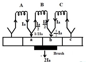
Fig. 25: Position 2
In this position total current will be 2Ia. The armature is rotating towards right and brushes are in contact with a. The current flows through two paths A and B. The current through coil B is ¾ of 2Ia and ¼ from coil A.
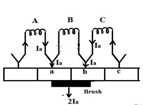
Fig. 26: Position 3
In this position half of the brush surface is in contact with segment a and the other half is with segment b. As the total current drawn trough brush is 2Ia, current Ia is drawn through coil A and Ia is drawn through coil B. Using KCL we can observe that the current in coil B will be zero.
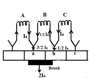
Fig. 27: Position 4
Now ¼ of the brush surface is in contact with segment b and ¾ with a. The current through coil B is -Ia/2. Hence current is reversed.
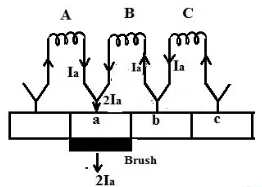
Fig. 28: Position 5
In this position, the brush is in full contact with segment a and the current from coil B is Ia but is in reverse direction to the current direction of position1.Thus commutation process is completed for segment b.
As we have already discussed in section 4.8 about ideal commutation. If at the end of the commutation period, when the trailing tip of the brush is going to break contact with segment, the coil current has not reversed and acquired full value. The breaking of current at the trailing brush tip takes place causing sparking. This is known as under-commutation (or delayed-commutation). The plot below shows under and over commutation.
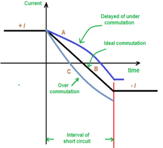
Fig. 29: Under and Over Commutation
The curve A in above figure shows Delayed commutation. The curve B is ideal commutation curve because the current changes from +I to -I linearly.
Key takeaway
There are two ways of achieving good commutation—close to straight-line commutation. These are resistance commutation and voltage commutation.
By saying bad commutation, we only mean Sparking and burning while commutation. It can occur because of following reasons:
1.When Brushes position is not proper.
2. When spaces between brushes is not proper. This may be checked by marking an adding-machine tape around the commutator.
3. Mica should be between bars undercut about 0.063 in below the commutating surface.
4.When commutator is not ground, resulting in rough or burned commutator. Rough or burned commutator.
5. Grooved commutator. This may be prevented by properly staggering the brush sets so that the spaces between the brushes of an arm are covered by brushes of the same polarity of other arms.
6.When it has poor brush contact. It may be due to improper fitting of brush to commutator surface.
7.The brushes are not replaced correctly, i.e of same size or grade.
8.When the brushes do not move freely in their holder, irregularity occurs. This is called sticking brushes.
9.When operated for current density below 35A/in2,may lead to chattering of brushes. This can be corrected by lifting brushes to raise density
10. Due to poor line up or inadequate foundation Vibration occur.
11.The Short-circuited turns on the commutating or compensating fields can be the reason for bad commutation.
12. Because of open or very high resistance joints between the commutator neck and the coil leads can lead to the burning of bar at the bad joint.
13. A broken coil conductor produces an effect similar to that produced by the poor joints. In case of emergency the open coil may be opened at both ends, insulated from the circuit, and a jumper placed across the two affected necks.
14.With the resulting unbalanced air-gap fluxes under the poles, large circulating currents must be expected even with good armature cross connections.
15. Overloading.
Remedies:
There are basically three methods of improving commutation.
i)Resistance Commutation
Ii)Voltage Commutation
Iii)Compensation Windings
Below are explained briefly the methods of improving commutation
i) Resistance Commutation: The Resistance Commutation can be obtained by replacing low resistance copper brushes with high resistance carbon brushes. The use of Carbon brushes makes the contact resistance between commutator segments and brushes high. This high contact resistance has the tendency to force the current in the short-circuited coil to change according to the commutation requirements.
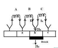
Fig. 30: Resistance commutation
As seen from figure above Ia from the coil C cab reach brushes from two paths in commutation period. One path is direct through the commutator segment b and to the brush and the 2nd path is first through the short-circuit coil B and then through the commutator segment a and to the brush. The second path is shorter. When we use high resistance brushes then the contact area of brush with B decreases and contact area with A increases. But the resistance is inversely proportional to the contact area. So, Ra will decrease and Rb will increase according to the movement of brush.
Ii) Voltage Commutation: This method has two ways to improve commutation
a) Brush Shift
b) Commutating poles or interpoles.
In this method a voltage is induced in the coil undergoing commutation. This will help to neutralise the reactance voltage. The both voltages are opposing each other. So, when injected and reactance voltages are equal, the direction of current in short circuited coil reverses, helping to attain sparkles commutation.
a) Brush Shift: The effect of armature reaction is to shift the magnetic neutral axis (MNA) in the direction of rotation for the generator and against the direction of rotation for the motor. Armature reaction establishes a flux in the neutral zone. A small voltage is induced in the commutating coil since it is cutting the flux.
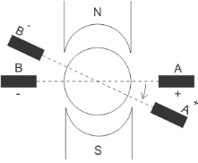
Fig. 31: Brush Shift
b) Interpoles: The main function of interpoles is to induce an emf which is equal and opposite to that of reactance emf, which makes commutation sparkles. They also neutralize the cross-magnetizing effect of armature reaction.
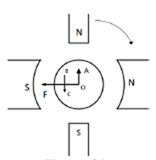
Fig. 32: Interpoles
In above figure OF=MMF due to main poles.
OA=Cross Magnetizing MMF due to armature
BC= MMF due to interpoles.
BC is in opposition to OA. Hence it helps to cancel cross magnetization due to OA.
The ampere turns needed to cancel armature reaction ampere turn and to create the required flux is given as
ATi=ATa(peak)+
Bi=Flux density in interpole air gap
 =air gap of interpoles
Key takeaway
There are basically three methods of improving commutation.
i)Resistance Commutation
Ii)Voltage Commutation
Iii)Compensation Windings
Que) A 440V, 4 pole, 20kW, dc generator has a wave connected armature winding with 800 conductors. The mean flux density in the air gap under interpoles is 0.5Wb/m2 on full load and the radial air gap length is 0.3 cm. Calculate the number of turns required in each pole?
Sol: From equation ATi=ATa(peak)+ =
=
Ia=20,000/440=45.45A
ATi=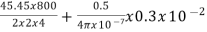 =3466.16
Ni= =
= =76.26=76
Hence 76 turns are required in each pole.
References
[1] Edward Hughes “Electrical Technology”, ELBS, Pearson Education.
[2] Ashfaq Husain, “Electrical Machines”, Dhanpat Rai& Sons.
[3] S. K. Bhattacharya, “Electrical Machine”, Tata McGraw Hill publishing Co. Ltd, 2nd Edition.
[4] Nagrath & Kothari, “Electrical Machines”, Tata McGraw Hill.
[5] Bhag S Guru, Husein R. Hiziroglu, “Electrical Machines”, Oxford University Press.
[6] K Krishna Reddy, “Electrical Machines- I and II”, SCITECH Publications (India) Pvt. Ltd. Chennai.


